2AMSURC9A2.4G Wireless Mouse Receiver
SANWA LIMITED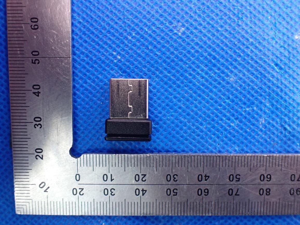
Click to zoom
Application Details
- Equipment Class
- DTS - Digital Transmission System
- Date of Grant
- Jan 19, 2022
- Application Purpose
- Original Equipment
- Date of Application
- Jan 19, 2022
- Equipment Note
- 2.4G Wireless Mouse Receiver
- Frequency Range
- 2403.00000000 - 2480.00000000
- Company
- SANWA LIMITED
- Country
- China
Documents & Files
Document Text
Text extracted from the exhibit documents filed with the FCC. Open a document above to read the original.
Users Manual
2.4G Wireless Mouse Receiver SANWA RC9A FCC ID: 2AMSURC9A Manufacturer:Dongguan Togran Electronics Co., Ltd Address:No.262, Shi Dan Rd., Juzhou, Shijia Town, Dongguan City, Guangdong, China User Guide How to pair USB radio dongle with the mouse 1. Plug the USB radio dongle into the USB port of the target device. 2. Press left+middle+right keys on the mouse. The LED will start blinking 3. Place the mouse close to the USB radio dongle (no farther than 10 cm). 4. After successful pairing, the LED will go off. How to use USB radio dongle with the mouse 1. Plug the USB radio dongle into the USB port of the target device. 2. Press any key on the mouse to activate connection to the USB radio dongle. NOTE: This equipment has been tested and found to comply with the limits for a Class B digital device, pursuant to part 15 of the FCC Rules. These limits are designed to provide reasonable protection against harmful interference in a residential installation. This equipment generates uses and can radiate radio frequency energy and, if not installed and used in accordance with the instructions, may cause harmful interference to radio communications. However, there is no guarantee that interference will not occur in a particular installation. If this equipment does cause harmful interference to radio or television reception, which can be determined by turning the equipment off and on, the user is encouraged to try to correct the interference by one or more of the following measures: - Reorient or relocate the receiving antenna. - Increase the separation between the equipment and receiver. -Connect the equipment into an outlet on a circuit different from that to which the receiver is connected. -Consult the dealer or an experienced radio/TV technician for help Changes or modifications not expressly approved by the party responsible for compliance could void the user's authority to operate the equipment. This device complies with Part 15 of the FCC Rules. Operation is subject to the following two conditions: (1) this device may not cause harmful interference, and (2) this device must accept any interference received, including interference that may cause undesired operation.
Cover Letter(s)
SANWA LIMITED Room 1005, 10/F., Tower 2, Silvercord, 30 Canton Road, Tsim Sha Tsui, Kowloon, Hong Kong, China Office of Engineering Technology Federal Communications Commission 7435 Oakland Mills Road Columbia, MD 21046 USA Date: Dec. 23, 2021 Subject; Request for Confidentiality FCC ID: 2AMSURC9A To Whom It May Concern, Pursuant to the provisions of the Commission’s rules Title 47 Sections §0.457 and §0.459, we are requesting the Commission to withhold the following attachment(s) as confidential documents from public disclosure indefinitely. These documents contain detailed system and equipment descriptions and are considered as proprietary information in operation of the equipment. The public disclosure of these documents might be harmful to our company and would give competitors an unfair advantage in the market. Schematic Diagram Block Diagram Operational Description Parts List Tune-up Procedure In additional to above mentioned documents, in order to comply with the marketing regulations in Title 47 CFR §2.803 and the importation rules in Title 47 CFR §2.1204, while ensuring that business sensitive information remains confidential until the actual marketing of newly authorized devices, we request Short Term Confidentiality of the following attachment(s); External Photos Test Setup Photos Internal Photos User Manual For 45 days, pursuant to Public Notice DA 04-1705. OR For 180 days pursuant to KDB 726920 D01. It is our understanding that all measurement test reports, FCC ID label format and correspondence during the certification review process cannot be granted as confidential documents and this information will be available for public review once the grant of equipment authorization is issued. Sincerely, Signature: Name: Yuzo Yamada Title: General Manager
External Photos
Report No.: AGC00688210611AP02 Page 1 of 3 EXTERNAL PHOTOS TOP VIEW OF EUT BOTTOM VIEW OF EUT Report No.: AGC00688210611AP02 Page 2 of 3 FRONT VIEW OF EUT BACK VIEW OF EUT Report No.: AGC00688210611AP02 Page 3 of 3 LEFT VIEW OF EUT RIGHT VIEW OF EUT ****************************************End of Report****************************************
ID Label/Location Info
FCC ID Label Location The product does not have enough space to place the label, and FCC ID label is located in the user manual and package. User manual as below:
Internal Photos
Report No.: AGC00688210611AP02 Page 1 of 3 INTERNAL PHOTOS OPEN VIEW OF EUT INTERNAL VIEW OF EUT-1 Report No.: AGC00688210611AP02 Page 2 of 3 INTERNAL VIEW OF EUT-2 INTERNAL VIEW OF EUT-3 Report No.: AGC00688210611AP02 Page 3 of 3 INTERNAL VIEW OF EUT-4 ****************************************End of Report**************************************** Antenna
Test Report
Page 1 of 44 FCC Test Report Report No.: AGC00688210611FE02 FCC ID : 2AMSURC9A APPLICATION PURPOSE : Original Equipment PRODUCT DESIGNATION : 2.4G Wireless Mouse Receiver BRAND NAME : SANWA MODEL NAME : SANWA RC9A APPLICANT : SANWA LIMITED DATE OF ISSUE : Dec. 22, 2021 STANDARD(S) : FCC Part 15.247 REPORT VERSION : V1.0 Attestation of Global Compliance (Shenzhen) Co., Ltd Report No.: AGC00688210611FE02 Page 2 of 44 REPORT REVISE RECORD Report Version Revise Time Issued Date Valid Version Notes V1.0 / Dec. 22, 2021 Valid Initial Release Report No.: AGC00688210611FE02 Page 3 of 44 TABLE OF CONTENTS 1. VERIFICATION OF COMPLIANCE .................................................................................................................. 5 2. GENERAL INFORMATION .............................................................................................................................. 6 2.1. PRODUCT DESCRIPTION ........................................................................................................................ 6 2.2. TABLE OF CARRIER FREQUENCYS ....................................................................................................... 6 2.3. RELATED SUBMITTAL(S)/GRANT(S) ....................................................................................................... 7 2.4. TEST METHODOLOGY ............................................................................................................................. 7 2.5. SPECIAL ACCESSORIES .......................................................................................................................... 7 2.6. EQUIPMENT MODIFICATIONS ................................................................................................................. 7 2.7. ANTENNA REQUIREMENT ....................................................................................................................... 7 3. MEASUREMENT UNCERTAINTY ................................................................................................................... 8 4. DESCRIPTION OF TEST MODES ................................................................................................................... 9 5. SYSTEM TEST CONFIGURATION ................................................................................................................ 10 5.1. CONFIGURATION OF TESTED SYSTEM ............................................................................................... 10 5.2. EQUIPMENT USED IN TESTED SYSTEM .............................................................................................. 10 5.3. SUMMARY OF TEST RESULTS .............................................................................................................. 10 6. TEST FACILITY .............................................................................................................................................. 11 7. PEAK OUTPUT POWER ................................................................................................................................ 12 7.1. MEASUREMENT PROCEDURE .............................................................................................................. 12 7.2. TEST SET-UP (BLOCK DIAGRAM OF CONFIGURATION) .................................................................... 12 7.3. LIMITS AND MEASUREMENT RESULT .................................................................................................. 13 8. BANDWIDTH .................................................................................................................................................. 15 8.1. MEASUREMENT PROCEDURE .............................................................................................................. 15 8.2. TEST SET-UP (BLOCK DIAGRAM OF CONFIGURATION) .................................................................... 15 8.3. LIMITS AND MEASUREMENT RESULTS ............................................................................................... 15 9. CONDUCTED SPURIOUS EMISSION........................................................................................................... 19 9.1. MEASUREMENT PROCEDURE .............................................................................................................. 19 9.2. TEST SET-UP (BLOCK DIAGRAM OF CONFIGURATION) .................................................................... 19 9.3. MEASUREMENT EQUIPMENT USED .................................................................................................... 19 9.4. LIMITS AND MEASUREMENT RESULT .................................................................................................. 19 10. MAXIMUM CONDUCTED OUTPUT POWER SPECTRAL DENSITY ........................................................ 26 Report No.: AGC00688210611FE02 Page 4 of 44 10.1. MEASUREMENT PROCEDURE ............................................................................................................ 26 10.2. TEST SET-UP (BLOCK DIAGRAM OF CONFIGURATION) .................................................................. 26 10.3. MEASUREMENT EQUIPMENT USED .................................................................................................. 26 10.4. LIMITS AND MEASUREMENT RESULT................................................................................................ 26 11. RADIATED EMISSION ................................................................................................................................. 28 11.1. MEASUREMENT PROCEDURE ............................................................................................................ 28 11.2. TEST SETUP .......................................................................................................................................... 29 11.3. LIMITS AND MEASUREMENT RESULT................................................................................................ …
Text truncated - open the document above for the full version.
Test Setup Photos
Report No.: AGC00688210611AP01 Page 1 of 2 TEST SETUP PHOTOS RADIATED EMISSION TEST SETUP BELOW 1GHz RADIATED EMISSION TEST SETUP ABOVE 1GHz Report No.: AGC00688210611AP01 Page 2 of 2 AC POWER LINE CONDUCTED TEST SETUP RF CONDUCTED TEST SETUP ****************************************End of Report*************************************
Contact Information
Applicant
Yuzo Yamada
Test Firm
Attestation of Global Compliance (Shenzhen) Co., LDoris Li
[email protected]+86-755-25234088
Technical Specifications
| # | Rule Parts | Frequency Range | Power Output |
|---|---|---|---|
| 1 | 15C | 2.40 GHz - 2.48 GHz | 150.00 µW |
Other Applications from SANWA LIMITED
2AMSUBT156
Nov 08, 2022Ring Bluetooth Mouse
Equipment Class
DTS - Digital Transmission System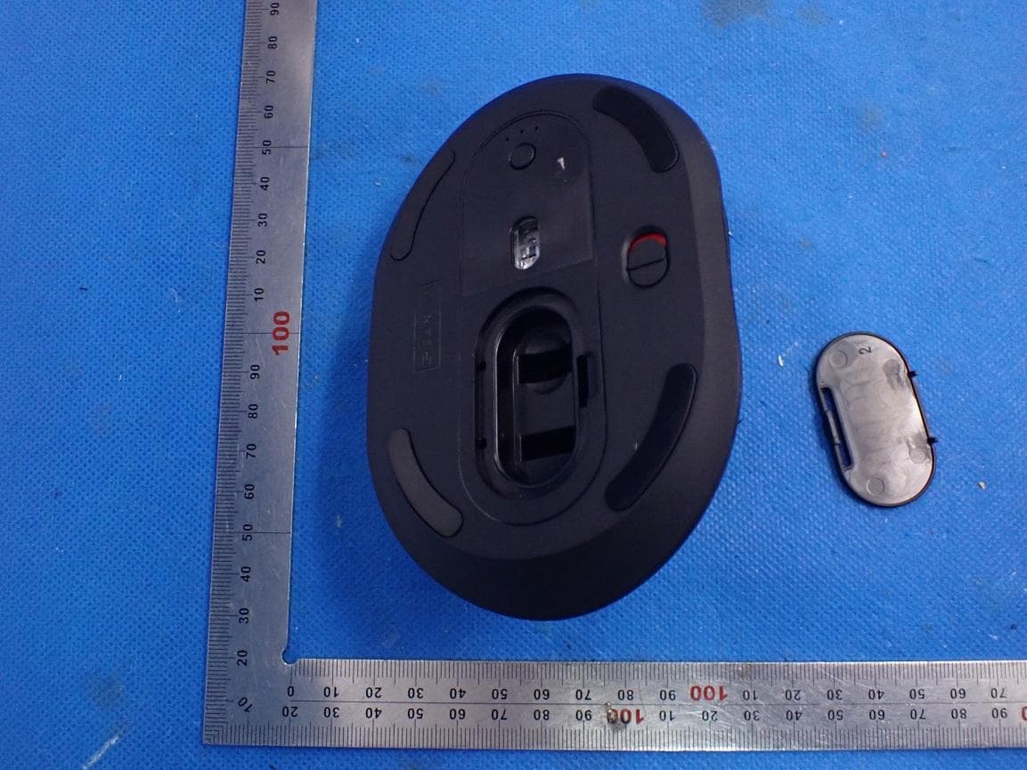
2AMSUDBT10
Jun 08, 2021Bluetooth Wireless Dual Mode Mouse
Equipment Class
DTS - Digital Transmission System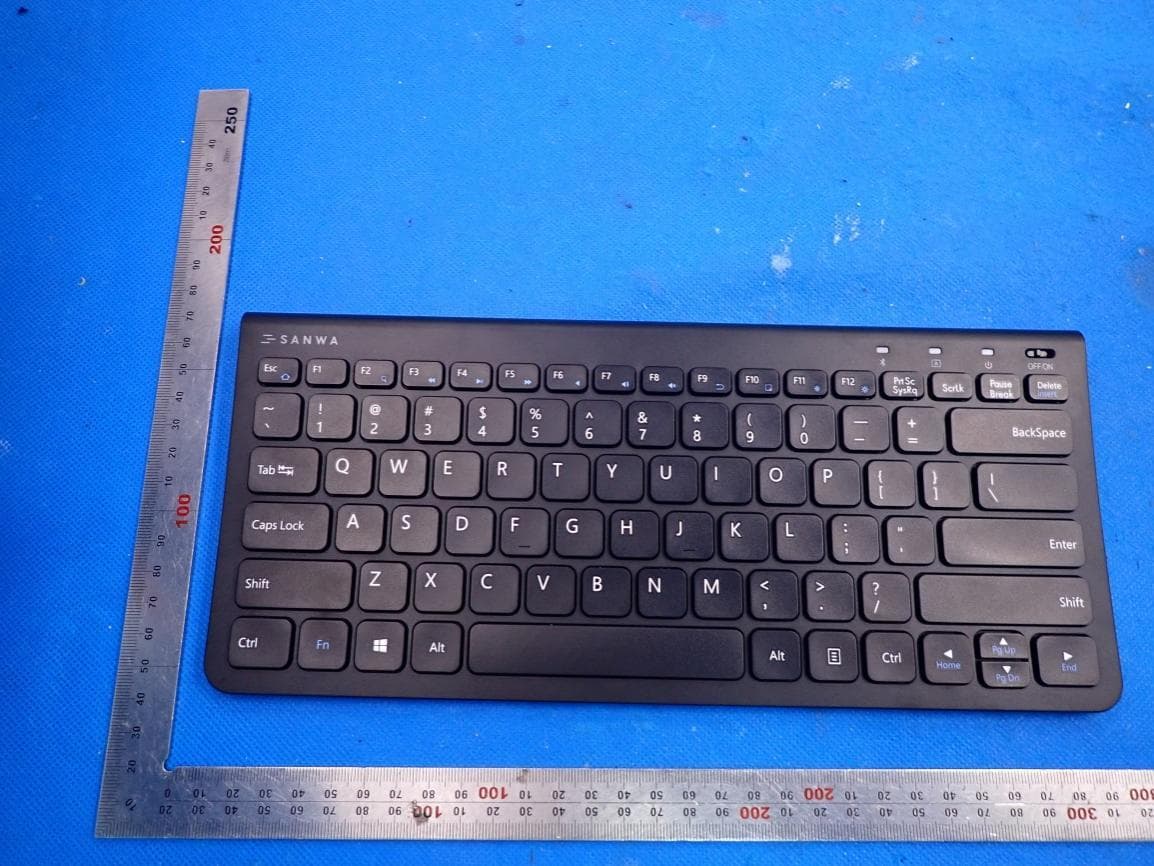
2AMSUW065E
May 25, 20212.4G Wireless Keyboard
Equipment Class
DTS - Digital Transmission System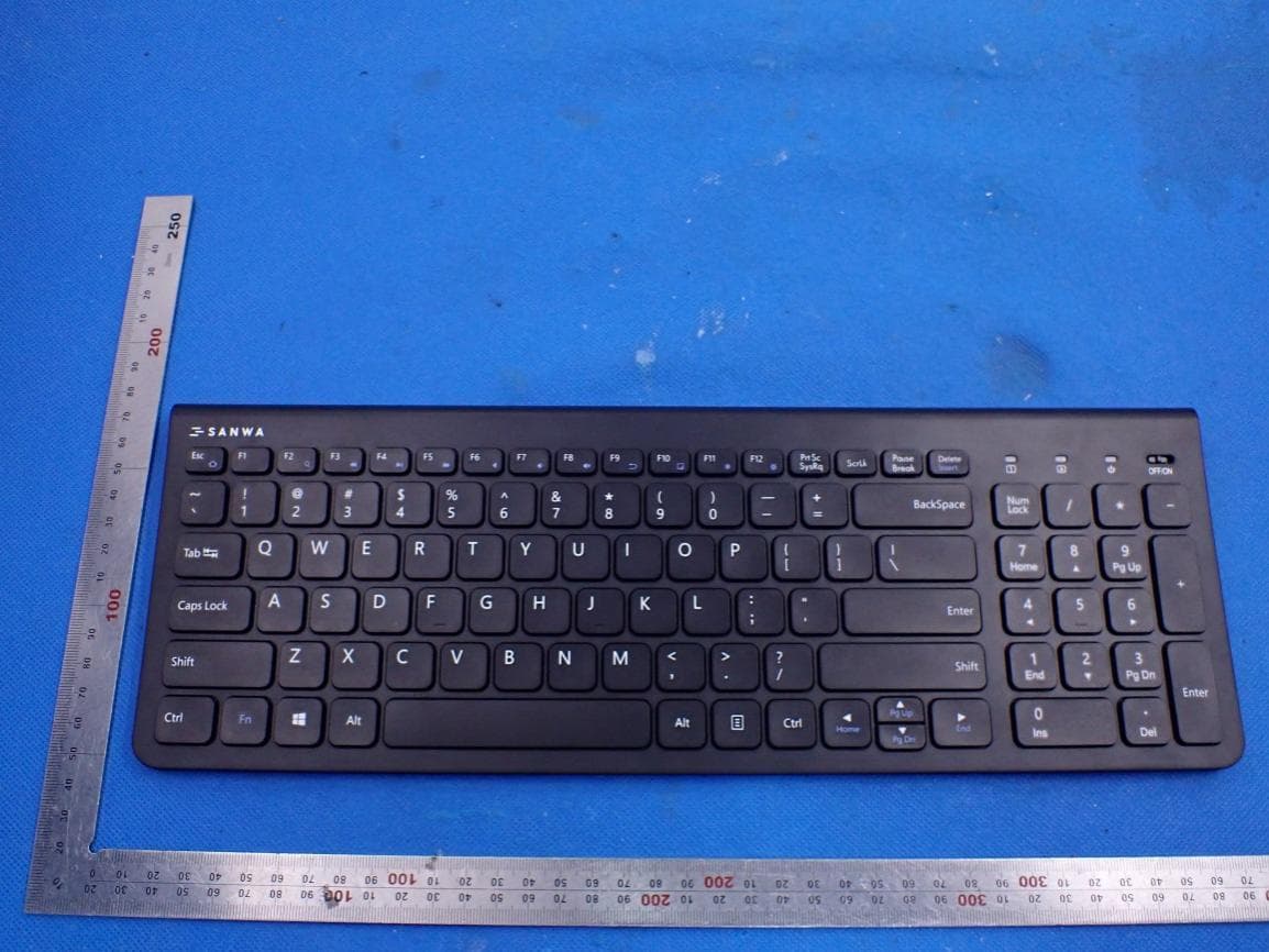
2AMSUW064E
May 25, 20212.4G Wireless Keyboard
Equipment Class
DTS - Digital Transmission System
2AMSUGBT1L
Jan 13, 2021Bluetooth Keyboard
Equipment Class
DSS - Part 15 Spread Spectrum Transmitter