2AMV5-LST04WRWiFi+RF Smart Strip Light
Changxing Potek Electronics & Technology Co., Ltd.
Click to zoom
Application Details
- Equipment Class
- DTS - Digital Transmission System
- Date of Grant
- Jul 20, 2020
- Application Purpose
- Original Equipment
- Date of Application
- Jul 20, 2020
- Equipment Note
- WiFi+RF Smart Strip Light
- Frequency Range
- 2412.00000000 - 2462.00000000
- Country
- China
Documents & Files
Document Text
Text extracted from the exhibit documents filed with the FCC. Open a document above to read the original.
Users Manual
LST04-WR User Manual 版本号: V1.1 版次修订内容修订人生效日期 V1.0 新颁姬敏杰 2020.05.1 6 V1.1 完善初版姬敏杰 2020.05.1 6 一、 Function summary LST04-WR is an RGB+W light belt that supports mobile phone WIFI communication and RF remote control. It is a smart light belt with functions such as scene mode, dimming and toning, white light mode, and timing. 二、 The product suit icon 备注:电源为图示,实际待确认,规格是24V/1ADC(带DC接头)。灯带控制器TYPE_C 连接灯带,右边DC接头连接24V电源。1pcs 5 meter light strip+1 pcs 24V/1A power adaptor+1pcs controller (type C connect the light strip, DC connector connect the power adaptor)+1 pcs transmitter 三、 Product parameters 外观 产品型号Model#LST04-WR 灯带尺寸Size of light strip10*5000mm 每米灯珠个数LED qty/meter 30PCS5050 灯珠/30PCS2835 暖白灯珠 30pcs 5050 RGB LED/30pcs 2835 2700K LED 白光灯珠 2835 色温范围2835 LED color temperature range 2700K±10% 白光灯珠流明值范围 The lumen value range of 2835 LED 1100lm±20% 控制器尺寸Size of controller80*29.1mm 产品颜色product colorWhite 产品重量/ 产品参数 Product Parameter 电源输入电压/电流 Power input voltage/current AC 120v/60Hz,0.3A(Max) 电源输出电压/电流 Power output voltage/current DC 24V,1A(Max) WiFi 参数WiFi parameter 支持协议 802.11 b/g/n;通道 [email protected];支持 WPA/WPA2 安全 support 802.11 b/g/n;WIFI channel [email protected];supportWPA/WPA2 security protocols RF 参数RF parameterFSK 915Mhz, Remote control distance>30M 待机功耗 stand-by power consumption <0.5W( The power supply parameters have been modified and the stand-by power consumption need to be reconfirmed ) 手机系统要求 Smartphone system requirements iOS 8.0 及以上版本; iOS 8.0 and above Android4.4 及以上系统的手机 Android 4.4 and above 四、 Instructions for use Instruction of RF resync code and reset WIFI LST04-WR是一款智能WIFI灯带,主要功能是通过手机APP以及RF遥控器实现的。 使用该设备WIFI功能之前,需要先进行添加设备。 LST04-WR is an intelligent WIFI+RF light strip. The main functions are realized through APP and RF remote control. Before using the WIFI function of this device, the device needs to be added first. 产品的壳体正面有一个按键。按键操作分为两种:点按和长按。 There is a button on the front of the housing of the product controller. There are two types operation of button: click and long press. ·点按控制灯带的开关,开启时灯带点亮,关闭时灭。 Click the button to turn on/off the light strip. The light strip will be lightened when turn on and be dark when turn off. ·灯带关闭时长按进入配网模式:未配网则会进入EZ配网模式(万能模式);EZ模式下 继续长按进入AP配网模式(指定热点配网);继续长按会在AP-EZ之间模式切换;已配 网则会重置WIFI。 When the light strip is turned off, long press the button on the controller, it will enter the pairing network mode. If not enter the pairing network mode, it will enter the EZ mode (universal mode). Continue to long press the button under the EZ mode to enter AP mode (pairing network under specified hot spot ); Continue to long press the button will switch between the AP-EZ mode; WIFI will be reset when the network have finished the pairing. ·灯带打开时长按:灯带切换回白光,并调节亮度。 When the light strip is turned on, long press the button on the controller, it will switch to white light and adjust the brightness. ·RF配对方式:控制器上电30S内来回按下第一组ON/OFF按键,若设备受控,表示学 习完成; RF pairing method: After the light strip power on, press the first row ON/OFF button on the transmitter repeatedly within 30 seconds. If the device is controlled, stands for the syncing is finished. LST04-WR遥控器功能说明:Description of transmitter function: ON:打开灯带turn on the light strip OFF:关闭灯带turn off the light strip UP:灯带切换为白光亮度增加light strip switch to white light and the brightness increased DOWN:灯带切换为白光亮度减小light strip switch to white light and the brightness decreased. MODE1:闪烁模式。flash mode MODE2:跳变模式jump mode RGB:通过RF来选择,RGB色彩choose the RGB through RF MODE3:呼吸模式breathing mode 2. LST04-WR手机APP功能说明 Description of APP function UI 1 UI 2 UI 3 界面以及功能介绍Interface and function introduction 界面1:APP面板打开的默认状态:可以通过开关来开关灯带 UI1: Default status of open APP panel: you can turn on and off the light strip by switch. 界面2:调色盘面板,可以选择灯带的色彩、亮度以及浓度等参数 UI 2:Palette panel, you can choose the color, brightness, dimming and other parameters. 界面3:场景模式选择面板,点按进入到对应的场景模式,点击编辑进入到设置该场景模式设 置界面 UI 3:Scene mode selection panel, click it and enter to the corresponding scene pattern, Click edit to enter the setting interface of this scene mode 五、使用方法Using Method ( 一 ) 下载 APP download the APP 使用手机扫描下方二维码下载APP,也可在各大应用商店搜索“SmartlinkPlus”下载安装APP Use your phone to scan the below QR code to download the APP, or search for "SmartlinkPlus" to download and install the APP in the APP stores ( 二 ) 连接 WIFI Connect the WIFI 打开APP注册登录 》》手机连接WIFI》》连接灯带和控制器并通电 》》关闭模式下长按控制 器按键进入EZ配网模式 》》打开APP点击添加设备或者右上角“+”号按提示完成配网 》》连 接成功APP内可选择模式、色彩等。Open the APP toregister and login-----the smart phone should to connect the WIFI ------connect the light strip and controller and power it on----- long press the button on the controller to enter the EZ mode when the light strip is turned off------open the APP and click add device or “+” on the top right corner to finish pairing network according to the reminder------choose the mode and color after the APP connect successfully. ( 三 ) 连接 RF 发射器 Connect RF transmitter 连接灯带和控制器并通电 》》上电30S内来回按下第一组ON/OFF按键 》》若设备受控则连接 成功 》》使用遥控远距离选择开关、选色、模式等功能。Connect the light strip and controller and power it on-----repeatedly press the first row ON/OFF button within 30S-----if the device is controlled, connect successfully----use the transmitter to choose ON/OFF, color, mode and other functions. FCC STATEMENT : This device complies with Part 15 of the FCC Rules. Operation is subject to the following two conditions: (1)This device may not cause harmful interference, and (2)This device must accept any interference received, including interference that may cause undesired operation. Warning: Changes or modifications not expressly approved by the party responsible for compliance could void the user's authority to operate the equipment. NOTE: This equipment has been tested and found to comply with the limits for a Class B digital device, pursuant to Part 15 of the FCC Rules. These limits are designed to provide reasonable protection against harmful interference in a residential installation. This equipment generates uses and can radiate radio frequency energy and, if not installed …
Text truncated - open the document above for the full version.
External Photos
FCC ID: 2AMV5-LST04WR
ID Label/Location Info
Label Location On EUT Label Product Name: WiFi+RF Smart Strip Light Model No.: LST04-WR FCC ID: 2AMV5-LST04WR This device complies with Part 15 of the FCC Rules. Operation is subject to the following two conditions: (1) This device may not cause harmful interference, and (2)This device must accept any interference received, including interference that may cause undesired operation.
Internal Photos
FCC ID: 2AMV5-LST04WR ANT
Operational Description
version01 Changxing Potek Electronics & Technology Co., Ltd. Declaration concerning Antenna Specification It is hereby declared that the product Model No.: LST04-WR FCC ID : 2AMV5-LST04WR fulfills the requirement in FCC test relating to the antenna type. The device specified above confirms to the FCC recommendations for internal antenna type(s) described below: Model No. of antenna: N/A Type of antenna:PCB Antenna Gain of the antenna: 3 dBi Frequency range:2412-2462MHz The mounting of the antenna is fixed to the radio module and no other antenna should be used. Company name: Changxing Potek Electronics & Technology Co., Ltd. Address: No. 1218, Taihu Avenue, Taihu Subdistrict, Changxing County, Huzhou City, Zhejiang, P.R.C. City:Huzhou City ZIP / Postal code: N/A Country:China Place:ChinaDate: 2020-07-20 Signature:
RF Exposure Info
RF EXPOSURE EVALUATION According to FCC 1.1310: The criteria listed in the following table shall be used to evaluate the environment impact of human exposure to radio frequency(RF) Radiation as specified in §1.1307(b) FCC ID: 2AMV5-LST04WR EUT Specification EUTWiFi+RF Smart Strip Light Frequency band (Operating) WLAN: 2.412GHz ~ 2.462GHz WLAN: 5.18GHz ~ 5.24GHz WLAN: 5.745GHz ~ 5.825GHz Others: 2.402GHz~2.480GHz Device category Portable (<20cm separation) Mobile (>20cm separation) Others ___ Exposure classificationOccupational/Controlled exposure (S = 5mW/cm2) General Population/Uncontrolled exposure (S=1mW/cm2) Antenna diversitySingle antenna Multiple antennas Tx diversity Rx diversity Tx/Rx diversity Max. output power19.43dBm (0.0877W) Antenna gain (Max)3dBi Evaluation applied MPE Evaluation SAR Evaluation Limits for Maximum Permissible Exposure(MPE) Frequency Range(MHz) Electric Field Strength(V/m) Magnetic Field Strength(A/m) Power Density(mW/cm 2 ) Average Time (A) Limits for Occupational/Control Exposures 300-1500----F/3006 1500-100000----56 (B) Limits for General Population/Uncontrol Exposures 300-1500----F/15006 1500-100000----130 Friis transmission formula: Pd=(Pout*G)\(4*pi*R2) Where Pd= Power density in mW/cm 2 Pout=output power to antenna in Mw G= gain of antenna in linear scale Pi=3.1416 R= distance between observation point and center of the radiator in cm Pd the limit of MPE, 1mW/cm2. If we know the maximum gain of the antenna and total power input to the antenna, through the calculation, we will know the distance where the MPE limit is reached. Measurement Result 2.4GHz WiFi: Operating Mode Channel Frequency Measured Power Tune up tolerance Max. Tune up Power Antenna Gain Power density at 20cm Power density Limits (mW/cm 2 ) (MHz)(dBm)(dBm)(dBm)(dBi)(mW/ cm 2 ) 802.11b 241218.50 18.50±119.5030.03541 243717.64 17.64±118.6430.02901 246215.69 15.69±116.6930.01851 802.11g 241219.43 19.43±120.4330.04381 243719.14 19.14±120.1430.04101 246217.35 17.35±118.3530.02711 802.11n (HT20) 241219.26 19.26±120.263 0.0421 1 243718.99 18.99±119.9930.03961 246217.27 17.27±118.2730.02671
Test Report
Report No.: 18220WC00081901FCC ID: 2AMV5-LST04WRPage 1 of 61 Code:AB-RF-05-a FCC TEST REPORT Client Name: Changxing Potek Electronics & Technology Co., Ltd. Address: No. 1218, Taihu Avenue, Taihu Subdistrict, Changxing County, Huzhou City, Zhejiang, P.R.C. Product Name: WiFi+RF Smart Strip Light Date: Jul. 17, 2020 Shenzhen Anbotek Compliance Laboratory Limited Report No.: 18220WC00081901FCC ID: 2AMV5-LST04WRPage 2 of 61 Code:AB-RF-05-a Contents 1. General Information ............................................................................................................................................... 5 1.1. Client Information ....................................................................................................................................... 5 1.2. Description of Device (EUT) ..................................................................................................................... 5 1.3. Auxiliary Equipment Used During Test ................................................................................................... 5 1.4. Description of Test Modes ........................................................................................................................ 6 1.5. List of channels ........................................................................................................................................... 7 1.6. Description Of Test Setup ......................................................................................................................... 8 1.7. Test Equipment List .................................................................................................................................... 9 1.8. Measurement Uncertainty ....................................................................................................................... 10 1.9. Description of Test Facility ...................................................................................................................... 10 2. Summary of Test Results ................................................................................................................................... 11 3. Conducted Emission Test ................................................................................................................................... 12 3.1. Test Standard and Limit .......................................................................................................................... 12 3.2. Test Setup .................................................................................................................................................. 12 3.3. Test Procedure .......................................................................................................................................... 12 3.4. Test Data .................................................................................................................................................... 12 4. Radiation Spurious Emission and Band Edge ................................................................................................ 15 4.1. Test Standard and Limit .......................................................................................................................... 15 4.2. Test Setup .................................................................................................................................................. 15 4.3. Test Procedure .......................................................................................................................................... 16 4.4. Test Data .................................................................................................................................................... 17 5. Maximum Output Power Test ............................................................................................................................ 26 5.1. Test Standard and Limit .......................................................................................................................... 26 5.2. Test Setup .................................................................................................................................................. 26 5.3. Test Procedure .......................................................................................................................................... 26 5.4. Test Data .................................................................................................................................................... 26 6. 6DB Occupy Bandwidth Test ............................................................................................................................. 30 6.1. Test Standard and Limit .......................................................................................................................... 30 6.2. Test Setup ............................................................................................................................... ................... 30 6.3. Test Procedure .......................................................................................................................................... 30 6.4. Test Data .................................................................................................................................................... 30 7. Power Spectral Density Test .............................................................................................................................. 37 7.1. Test Standard and Limit .......................................................................................................................... 37 7.2. Test Setup .................................................................................................................................................. 37 7.3. Test Procedure ..............................................................................................…
Text truncated - open the document above for the full version.
Test Setup Photos
FCC ID: 2AMV5-LST04WR Photo of Conducted Emission Measurement Photo of Radiation Emission Test
Contact Information
Applicant
FIONA WEN(SALES V.P.)
Test Firm
Shenzhen Anbotek Compliance Laboratory LimitedJeff Zhu
Technical Specifications
| # | Rule Parts | Frequency Range | Power Output |
|---|---|---|---|
| 1 | 15C | 2.41 GHz - 2.46 GHz | 87.71 mW |
Other Applications from Changxing Potek Electronics & Technology Co., Ltd.
2AMV5-SK569-WU-AC
Jul 24, 2023Smart Power Strip
Equipment Class
DTS - Digital Transmission System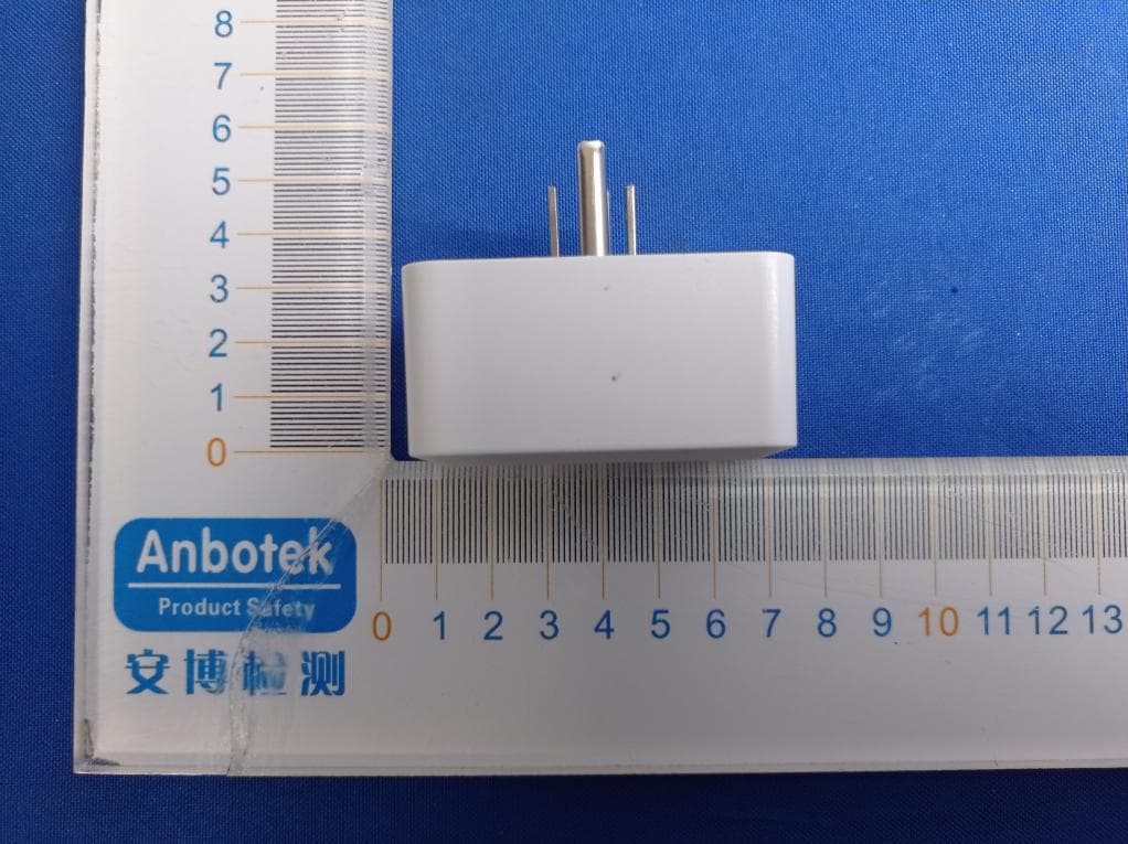
2AMV5-SK543-W-A
Jul 28, 20211-outlet indoor wifi smart plug
Equipment Class
DTS - Digital Transmission System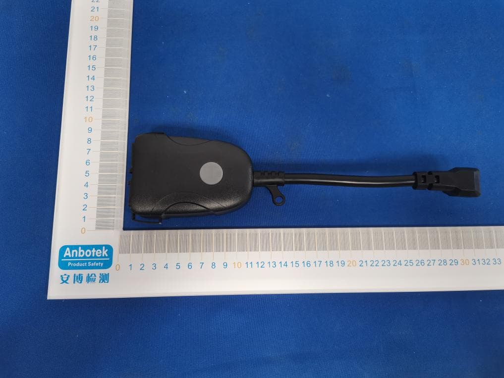
2AMV5-SK509WN
Jul 22, 20212-outlet outdoor wifi smart plug
Equipment Class
DTS - Digital Transmission System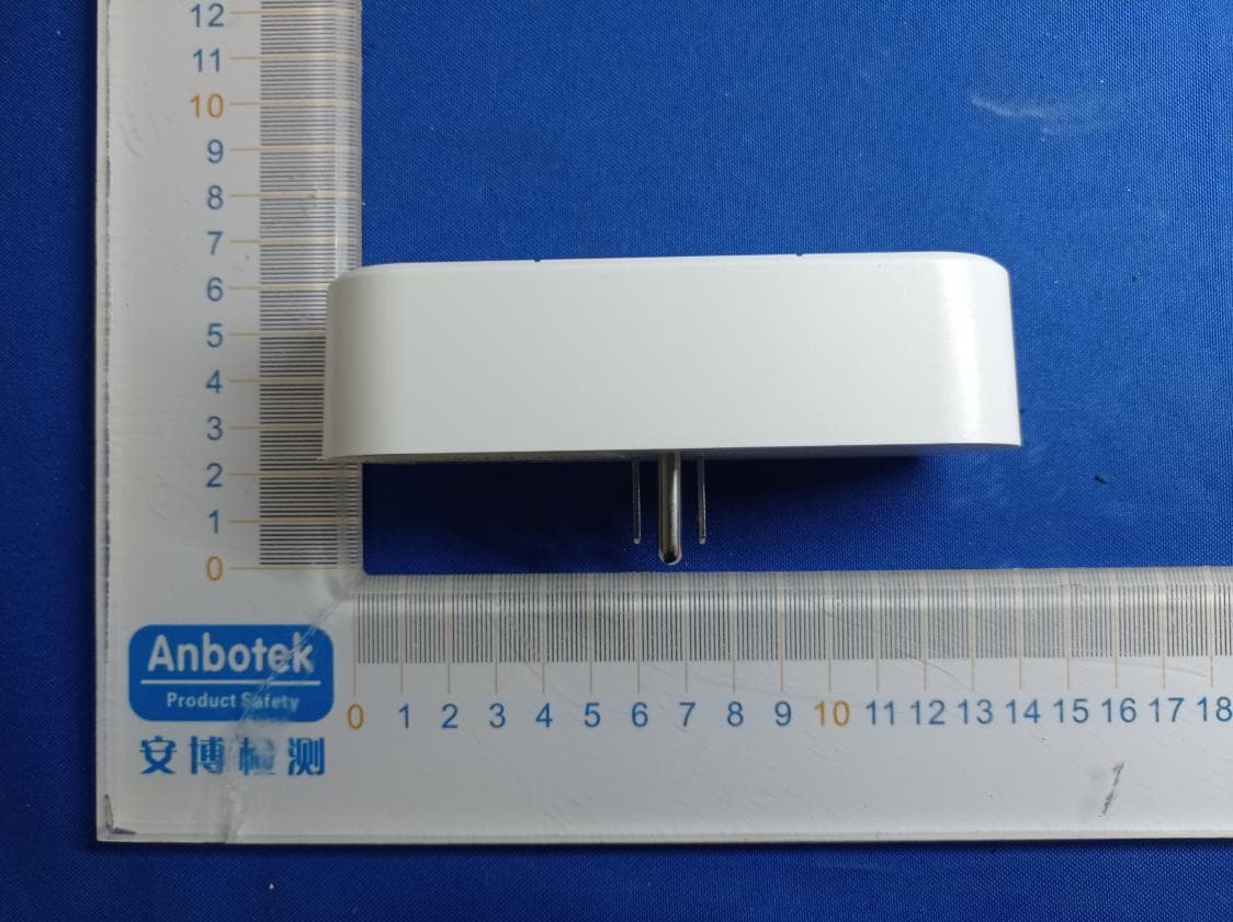
2AMV5-SK521-W-A
Jun 30, 20212-outlet simultaneously controlled indoor wifi smart plug
Equipment Class
DTS - Digital Transmission System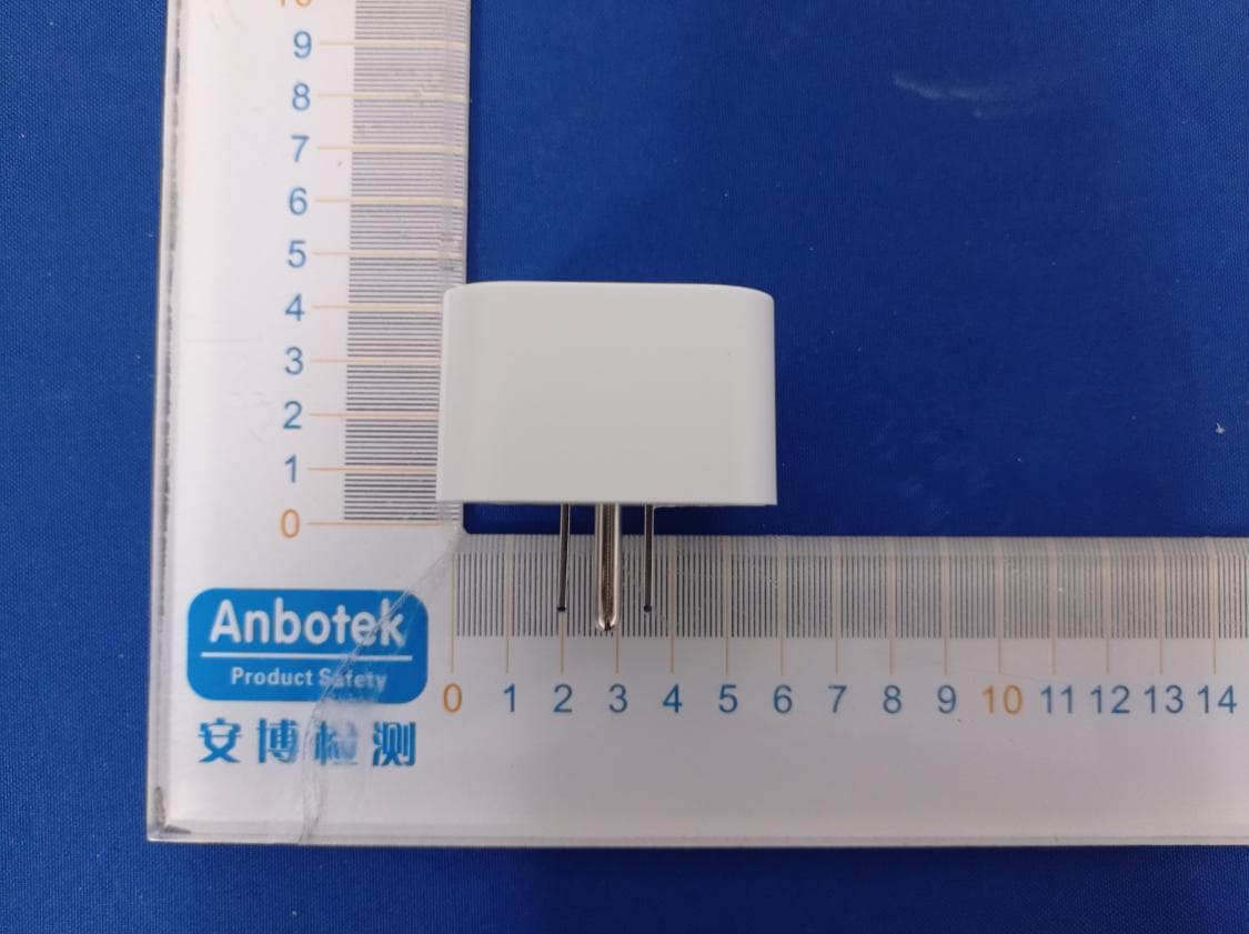
2AMV5-SK539-W-A
Jun 30, 20211-outlet indoor wifi smart plug
Equipment Class
DTS - Digital Transmission System