Text extracted from the exhibit documents filed with the FCC. Open a document above to read the original.
Company Name:M5Stack Technology Co.,Ltd Address: Block A10, Expo Bay South Coast, Fuhai Street, Bao'an District, Shenzhen,Guangdong,China PaperMono Company Name:M5Stack Technology Co.,Ltd Address: Block A10, Expo Bay South Coast, Fuhai Street, Bao'an District, Shenzhen,Guangdong,China 1. Description PaperMono is a development board featuring a 3.97-inch touch-enabled monochrome E- Paper display driven by the SSD1677 controller at a resolution of 480x800, supporting 1-bit black-and-white rendering. It integrates an FT6336G touch controller and a front-light illumination system for comfortable reading in dark or low-light environments. Powered by the ESP32-S3R8 SoC equipped with 16 MB flash memory and 8 MB PSRAM, it supports a 40MHz crystal oscillator, it supports 2.4 GHz Wi-Fi, BLE wireless communication. The board incorporates a buzzer, a PDM microphone (LMD4737T261-AC02), an RGB LED, a BMI270 6- axis IMU, an M5IOE1 IO expander, a microSD card slot, and an RX8130CE real-time clock. NFC capability is provided by the ST25R3916 high-performance frontend chip, supporting ISO14443A, ISO14443B, FeliCa™, and ISO15693 protocols for reliable read/write operations with various NFC/RFID tags and cards, with reader mode, card emulation mode, custom protocol support, automatic antenna tuning, and high-sensitivity reception. LoRa communication is based on the SX1262 chip (Stamp LoRa-1262) with a built- in FPC antenna, supporting the 868–923 MHz band with strong anti-interference and long- range communication capabilities. Combined with the M5PM1 multi-level power management system and a 1150mAh lithium battery, it delivers sustained low-power operation. Suitable for e-readers, electronic signage, access control systems, identity authentication, intelligent transportation, and other IoT and embedded applications. Company Name:M5Stack Technology Co.,Ltd Address: Block A10, Expo Bay South Coast, Fuhai Street, Bao'an District, Shenzhen,Guangdong,China 2. Specifications Specification Parameters SoC ESP32-S3R8 @ Dual-core Xtensa LX7 Processor, up to 240MHz PSRAM 8MB Flash 16MB Wi-Fi 2.4 GHz Wi-Fi: 2412-2462MHz BLE 2.4 GHz BLE: 2402-2480MHz Display 3.97" E-Paper (Mono) SSD1677 @ 480x800, Touch FT6336G Front Light Integrated E-Paper front light Power Input USB Type-C DC 5V Battery 1150mAh Microphone PDM microphone LMD4737T261-AC02 Buzzer Built-in buzzer IMU BMI270 IO Expander M5IOE1 External Storage microSD card RTC RX8130CE RGB LED Built-in RGB LED NFC ST25R3916 (ISO14443A/B, FeliCa™, ISO15693: 13.56MHz LoRa 903.0-914.9MHz User Keys 2x user keys + 1x power key (ON/OFF/RESET/BOOT) Hardware version NO V1.0 Software version NO V1.0 Company Name:M5Stack Technology Co.,Ltd Address: Block A10, Expo Bay South Coast, Fuhai Street, Bao'an District, Shenzhen,Guangdong,China 3. Quick Start 3.1 Preparation 1. Visit the official Arduino website and install the Arduino IDE https://www.arduino.cc/en/Main/Software 2. Add the following Board Manager URL to File → Preferences → Additional Boards Manager URLs: https://espressif.github.io/arduino-esp32/package_esp32_dev_index.json Company Name:M5Stack Technology Co.,Ltd Address: Block A10, Expo Bay South Coast, Fuhai Street, Bao'an District, Shenzhen,Guangdong,China 3. Open the Boards Manager, search for "ESP32", and click install. Company Name:M5Stack Technology Co.,Ltd Address: Block A10, Expo Bay South Coast, Fuhai Street, Bao'an District, Shenzhen,Guangdong,China 4. After installation, select the board "ESP32S3 Dev Module" 5. Configure the following options. USB CDC On Boot: "Enabled", PSRAM:"OPI PSRAM", USB Mode: "Hardware CDC and JTAG" Company Name:M5Stack Technology Co.,Ltd Address: Block A10, Expo Bay South Coast, Fuhai Street, Bao'an District, Shenzhen,Guangdong,China 3.2 Wi-Fi Scan Select the example program "Examples" → "WiFi" → "WiFiScan", choose the port corresponding to your device, and click the compile and upload button in the top-left corner. After uploading is complete, open the Serial Monitor to view Wi-Fi scan information. Company Name:M5Stack Technology Co.,Ltd Address: Block A10, Expo Bay South Coast, Fuhai Street, Bao'an District, Shenzhen,Guangdong,China 3.3 BLE Scan Select the example program "Examples" → "BLE" → ”Scan”, choose the port corresponding to your device, and click the compile and upload button in the top-left corner. After uploading is complete, open the Serial Monitor to view BLE scan information. Company Name:M5Stack Technology Co.,Ltd Address: Block A10, Expo Bay South Coast, Fuhai Street, Bao'an District, Shenzhen,Guangdong,China Company Name:M5Stack Technology Co.,Ltd Address: Block A10, Expo Bay South Coast, Fuhai Street, Bao'an District, Shenzhen,Guangdong,China 4. FCC Warning FCC Caution: Any Changes or modifications not expressly approved by the party responsible for compliance could void the user's authority to operate the equipment. This device complies with part 15 of the FCC Rules. Operation is subject to the following two conditions: (1) This device may not cause harmful interference, and (2) this device must accept any interference received, including interference that may cause undesired operation. IMPORTANT NOTE: Note: This equipment has been tested and found to comply with the limits for a Class B digital device, pursuant to part 15 of the FCC Rules. These limits are designed to provide reasonable protection against harmful interference in a residential installation. This equipment generates, uses and can radiate radio frequency energy and, if not installed and used in accordance with the instructions, may cause harmful interference to radio communications. However, there is no guarantee that interference will not occur in a particular installation. If this equipment does cause harmful interference to radio or television reception, which can be determined by turning the equipment off and on, the user is encouraged to try to correct the interference by one or more of the following measures: — Reorient or relocate the receivi…
Text truncated - open the document above for the full version.
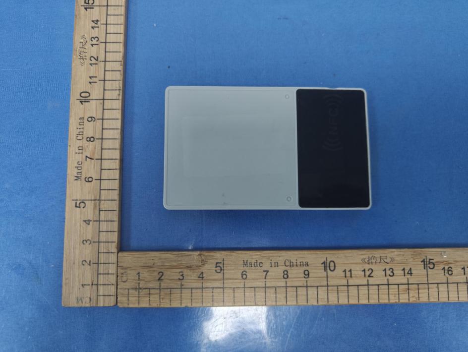
Shenzhen Accurate Technology Co., Ltd. No.: 2604T59815E-RF EUT External Photos External Photos Page 1 / 3 External Photos Shenzhen Accurate Technology Co., Ltd. No.: 2604T59815E-RF EUT External Photos External Photos Page 2 / 3 Shenzhen Accurate Technology Co., Ltd. No.: 2604T59815E-RF EUT External Photos External Photos Page 3 / 3 ***** END *****
Label Label location
Shenzhen Accurate Technology Co., Ltd. No.: 2604T59815E-RF EUT Internal Photos Internal Photos Page 1 / 7 Internal Photos Shenzhen Accurate Technology Co., Ltd. No.: 2604T59815E-RF EUT Internal Photos Internal Photos Page 2 / 7 Shenzhen Accurate Technology Co., Ltd. No.: 2604T59815E-RF EUT Internal Photos Internal Photos Page 3 / 7 Shenzhen Accurate Technology Co., Ltd. No.: 2604T59815E-RF EUT Internal Photos Internal Photos Page 4 / 7 Shenzhen Accurate Technology Co., Ltd. No.: 2604T59815E-RF EUT Internal Photos Internal Photos Page 5 / 7 BLE 2.4G WIFI ANT Shenzhen Accurate Technology Co., Ltd. No.: 2604T59815E-RF EUT Internal Photos Internal Photos Page 6 / 7 NFC LORA ANT 12 NFC ANT Shenzhen Accurate Technology Co., Ltd. No.: 2604T59815E-RF EUT Internal Photos Internal Photos Page 7 / 7 LORA ANT ***** END *****
Shenzhen Accurate Technology Co., Ltd. Report No.: 2604T59815E-RF-22C Rev:A/4.0(2024/11/01) Page 11 of 51 TR-4-E-R007 RF EXPOSURE Applicable Standard According to KDB447498 D01 General RF Exposure Guidance v06: 4.3. General SAR test exclusion guidance c) For frequencies below 100 MHz, the following may be considered for SAR test exclusion (also illustrated in Appendix C): 1) For test separation distances > 50 mm and < 200 mm, the power threshold at the corresponding test separation distance at 100 MHz in step b) is multiplied by [1 + log(100/f(MHz))] 2) For test separation distances ≤ 50 mm, the power threshold determined by the equation in c) 1) for 50 mm and 100 MHz is multiplied by ½. 3) SAR measurement procedures are not established below 100 MHz. Result For NFC, the power of EUT: E Field@3m is 66.65dBuV/m =-28.55dBm(0.0014mW) Note: E[dBμV/m] = EIRP[dBm] + 95.2for d = 3 m. SAR test exclusion threshold for NFC(13.56MHz) separation distance < 50mm =[474*(1 + log(100/f(MHz)))]/2 = 443mW >0.0014mW Result: Compliance.
The information marked “#” is provided by the applicant, the laboratory is not responsible for its authenticity and this information can affect the validity of the result in the test report. Customer model name, addresses, names, trademarks etc. are included but no need marked. This report cannot be reproduced except in full, without prior written approval of the Company. Unless otherwise stated the results shown in this test report refer only to the sample(s) tested. This report is valid only with a valid digital signature. The digital signature may be available only under the Adobe software above version 7.0. Shenzhen Accurate Technology Co., Ltd. Floor 1, KuMaKe Building, Dongzhou Community, Guangming Street, Guangming District, Shenzhen, Guangdong, China. Tel: +86 755-26503290 Web: www.atc-lab.com Rev:A/4.0(2024/11/01) Page 1 of 51 TR-4-E-R007 TEST REPORT Applicant Name: M5Stack Technology Co., Ltd Address: Block A10, Expo Bay South Coast, Fuhai Street, Bao'an District, Shenzhen, China Report Number: 2604T59815E-RF-22C FCC ID: 2AN3WM5PAPERMONO Test Standard (s) FCC PART 15.225 Sample Description Product Name: M5PaperMono Model No.: PaperMono Trade Mark: Received Date: 2026-05-21 Report Date: 2026-07-10 Test Result: The EUT complied with the standards above. Prepared and Checked By: Approved By: Roger Ling Bob.Liao EMC Engineer EMC Engineer Shenzhen Accurate Technology Co., Ltd. Report No.: 2604T59815E-RF-22C Rev:A/4.0(2024/11/01) Page 2 of 51 TR-4-E-R007 TABLE OF CONTENTS DOCUMENT REVISION HISTORY ................................................................................................................ 3 GENERAL INFORMATION ............................................................................................................................ 4 PRODUCT DESCRIPTION FOR EQUIPMENT UNDER TEST (EUT) ........................................................................ 4 OBJECTIVE ................................................................................................................................................... 4 TEST METHODOLOGY .................................................................................................................................... 4 TEST FACILITY .............................................................................................................................................. 5 MEASUREMENT UNCERTAINTY ....................................................................................................................... 5 SYSTEM TEST CONFIGURATION ............................................................................................................... 6 DESCRIPTION OF TEST CONFIGURATION ......................................................................................................... 6 EUT EXERCISE SOFTWARE ........................................................................................................................... 6 EQUIPMENT MODIFICATIONS .......................................................................................................................... 6 SUPPORT EQUIPMENT LIST AND DETAILS ....................................................................................................... 6 EXTERNAL I/O CABLE .................................................................................................................................... 6 BLOCK DIAGRAM OF TEST SETUP .................................................................................................................. 7 SUMMARY OF TEST RESULTS ................................................................................................................... 9 TEST EQUIPMENT LIST ............................................................................................................................. 10 RF EXPOSURE ............................................................................................................................................ 11 APPLICABLE STANDARD ............................................................................................................................... 11 RESULT ...................................................................................................................................................... 11 ANTENNA REQUIREMENT ........................................................................................................................ 12 APPLICABLE STANDARD ............................................................................................................................... 12 ANTENNA CONNECTED CONSTRUCTION ....................................................................................................... 12 AC LINE CONDUCTED EMISSION ............................................................................................................. 13 APPLICABLE STANDARD ............................................................................................................................... 13 EUT SETUP ................................................................................................................................................ 13 EMI TEST RECEIVER SETUP ........................................................................................................................ 13 TEST PROCEDURE ...................................................................................................................................... 14 CALCULATION ............................................................................................................................................. 14 TEST DATA ................................................................................................................................................. 14 RADIATED EMISSIONS TEST .................................................................................................................... 19 APPLICABLE STANDARD ...........................…
Text truncated - open the document above for the full version.
Shenzhen Accurate Technology Co., Ltd. No.: 2604T59815E-RF-00C Test Photos Test Photos Page 1 / 4 With Magnetic card Photo of Power Line Conducted Emission Measurement Shenzhen Accurate Technology Co., Ltd. No.: 2604T59815E-RF-00C Test Photos Test Photos Page 2 / 4 Radiated Spurious Emissions Test View (9kHz-30MHz) Radiated Spurious Emissions Test View (30MHz- 1GHz) Shenzhen Accurate Technology Co., Ltd. No.: 2604T59815E-RF-00C Test Photos Test Photos Page 3 / 4 Without Magnetic card Photo of Power Line Conducted Emission Measurement Shenzhen Accurate Technology Co., Ltd. No.: 2604T59815E-RF-00C Test Photos Test Photos Page 4 / 4 Radiated Spurious Emissions Test View (9kHz-30MHz) Radiated Spurious Emissions Test View (30MHz- 1GHz) ***** END *****
2310 Homestead Road Suite C1 · Los Altos, California, 94024 · United States
| # | Rule Parts | Frequency Range | Power Output |
|---|---|---|---|
| 1 | 15C | 13.56 MHz - 13.56 MHz | - |