2AN3WM5STAMPC5M5Stamp-C5
M5Stack Technology Co.,Ltd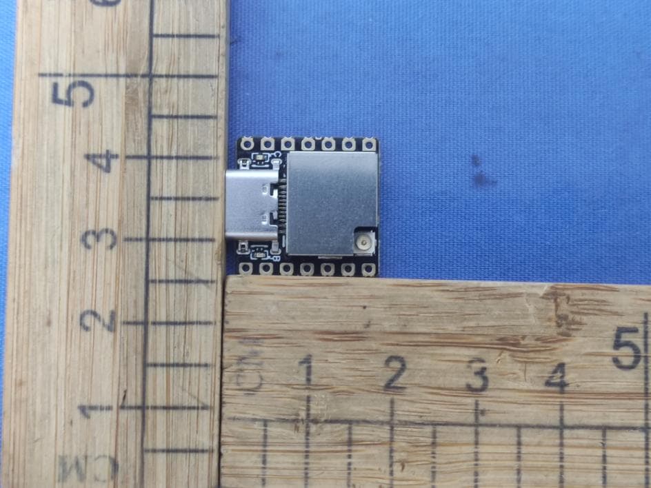
Click to zoom
Application Details
- Equipment Class
- DTS - Digital Transmission System
- Date of Grant
- Jul 24, 2026
- Application Purpose
- Original Equipment
- Equipment Note
- M5Stamp-C5
- Frequency Range
- 2402.00000000 - 2480.00000000
- Company
- M5Stack Technology Co.,Ltd
- Country
- China
Documents & Files
Document Text
Text extracted from the exhibit documents filed with the FCC. Open a document above to read the original.
Users Manual
Company Name:M5Stack Technology Co.,Ltd Address: Block A10, Expo Bay South Coast, Fuhai Street, Bao'an District, Shenzhen,Guangdong,China Stamp-C5 Company Name:M5Stack Technology Co.,Ltd Address: Block A10, Expo Bay South Coast, Fuhai Street, Bao'an District, Shenzhen,Guangdong,China 1. Description Stamp-C5 is a highly integrated wireless communication module built on Espressif's ESP32-C5HF4, specifically designed for IoT applications requiring efficient and stable communication. It supports multi-protocol connectivity, including 2.4 GHz and 5 GHz fully meeting the device access requirements in different network scenarios. The module is equipped with a 32-bit single-core RISC-V processor operating at up to 240 MHz, integrating 4 MB of on-board flash memory, a 48 MHz crystal oscillator, and a wealth of hardware peripherals such as USB Type-C ports, battery power interfaces, FPC expansion connectors, and IPEX-1 antenna connectors. It adopts a standard 2.54mm pad spacing, enabling seamless connection with various peripherals and facilitating flexible functional expansion. While providing reliable connectivity performance and strong security, this module can also help developers accelerate prototype verification and simplify the process of large-scale product deployment. Company Name:M5Stack Technology Co.,Ltd Address: Block A10, Expo Bay South Coast, Fuhai Street, Bao'an District, Shenzhen,Guangdong,China 2. Specifications Specification Parameters SoC ESP32-C5HF4, RISC-V 32-bit single-core processor, up to 240 MHz SRAM 384KB Flash 4MB Wi-Fi 2.4 & 5 G BLE BLE 5 USB Interface USB Type-C Battery Power Interface DC 3.7 V Antenna Interface IPEX-1 Dual-band Duplexer LFD182G45DCHD481 (shared antenna for 2.4 & 5 GHz) Charging IC SGM40567-4.2XG/TR Status Indicators 2 × LED (RED: Charging; BLUE: G28 / BOOT) GPIO Pins Total 19 × GPIO (11 × GPIO via pads + 8 × GPIO via FPC) Pad GPIO G1, G2, G3, G4, G5, G6, G7, G8, G9, G10, G28 FPC GPIO G23, G0, G24, G25, G26, G27, G11, G12 Pad Pitch 2.54 mm Expansion Interface 0.5 mm 12-Pin FPC Hardware version NO V1.0 Software version NO V1.0 Company Name:M5Stack Technology Co.,Ltd Address: Block A10, Expo Bay South Coast, Fuhai Street, Bao'an District, Shenzhen,Guangdong,China 3. Quick Start 3.1 Preparation 1. Visit the official Arduino website and install the Arduino IDE https://www.arduino.cc/en/Main/Software 2. Add the following Board Manager URL to File → Preferences → Additional Boards Manager URLs: https://espressif.github.io/arduino-esp32/package_esp32_dev_index.json Company Name:M5Stack Technology Co.,Ltd Address: Block A10, Expo Bay South Coast, Fuhai Street, Bao'an District, Shenzhen,Guangdong,China 3. Open the Boards Manager, search for "ESP32", and click install. Company Name:M5Stack Technology Co.,Ltd Address: Block A10, Expo Bay South Coast, Fuhai Street, Bao'an District, Shenzhen,Guangdong,China 4. After installation, select the board "ESP32C5 Dev Module" 5. Configure the following options. USB CDC On Boot: "Enabled" Company Name:M5Stack Technology Co.,Ltd Address: Block A10, Expo Bay South Coast, Fuhai Street, Bao'an District, Shenzhen,Guangdong,China 3.2 Wi-Fi Scan Select the example program "Examples" → "WiFi" → "WiFiScan", choose the port corresponding to your device, and click the compile and upload button in the top-left corner. After uploading is complete, open the Serial Monitor to view Wi-Fi scan information. Company Name:M5Stack Technology Co.,Ltd Address: Block A10, Expo Bay South Coast, Fuhai Street, Bao'an District, Shenzhen,Guangdong,China Company Name:M5Stack Technology Co.,Ltd Address: Block A10, Expo Bay South Coast, Fuhai Street, Bao'an District, Shenzhen,Guangdong,China 3.3 BLE Scan Select the example program "Examples" → "BLE" → ”Scan”, choose the port corresponding to your device, and click the compile and upload button in the top-left corner. After uploading is complete, open the Serial Monitor to view BLE scan information. Company Name:M5Stack Technology Co.,Ltd Address: Block A10, Expo Bay South Coast, Fuhai Street, Bao'an District, Shenzhen,Guangdong,China Company Name:M5Stack Technology Co.,Ltd Address: Block A10, Expo Bay South Coast, Fuhai Street, Bao'an District, Shenzhen,Guangdong,China 4. FCC Warning FCC Caution: Any Changes or modifications not expressly approved by the party responsible for compliance could void the user's authority to operate the equipment. This device complies with part 15 of the FCC Rules. Operation is subject to the following two conditions: (1) This device may not cause harmful interference, and (2) this device must accept any interference received, including interference that may cause undesired operation. IMPORTANT NOTE: Note: This equipment has been tested and found to comply with the limits for a Class B digital device, pursuant to part 15 of the FCC Rules. These limits are designed to provide reasonable protection against harmful interference in a residential installation. This equipment generates, uses and can radiate radio frequency energy and, if not installed and used in accordance with the instructions, may cause harmful interference to radio communications. However, there is no guarantee that interference will not occur in a particular installation. If this equipment does cause harmful interference to radio or television reception, which can be determined by turning the equipment off and on, the user is encouraged to try to correct the interference by one or more of the following measures: — Reorient or relocate the receiving antenna. — Increase the separation between the equipment and receiver. — Connect the equipment into an outlet on a circuit different from that to which the receiver is connected. — Consult the dealer or an experienced radio/TV technician for help. FCC Radiation Exposure Statement: This equipment complies with FCC radiation exposure limits set forth for an uncontrolled environment. This equipment should be installed and operated with minimum distance 20cm between the…
Text truncated - open the document above for the full version.
Cover Letter(s)
M5StackTechnologyCo.,Ltd Address:BlockA10,ExpoBaySouthCoast,FuhaiStreet,Bao'anDistrict,Shenzhen,Guangdong,China E-Mail:[email protected] Tel.:+8613509230623 FCCConfidentialAuthorization Date:2026-06-26 FEDERALCOMMUNICATIONSCOMMISSIONS AuthorizationandEvaluationDivision 7435OaklandMillsRoad Columbia,MD21046 Subject:ConfidentialityRequestregardingapplicationforcertificationof FCCID:2AN3WM5STAMPC5 InaccordancewithSections0.457and0.459oftheCommission’sRules,M5Stack TechnologyCo.,Ltdherebyrequestslong-termconfidentialtreatmentofinformation accompanyingthisapplicationasoutlinedbelow: BlockDiagram Schematics OperationDescription SoftwareSecurityDescription Theabovematerialscontainproprietaryandconfidentialinformationnotcustomarily releasedtothepublic.Thepublicdisclosureofthesematerialsprovidesunjustified benefitstoitscompetitorsinthemarket. SincerelyYours, Signature: JimmyLai CEO
Cover Letter(s)
M5StackTechnologyCo.,Ltd Address:BlockA10,ExpoBaySouthCoast,FuhaiStreet,Bao'anDistrict, Shenzhen,Guangdong,China Tel.:+8613509230623 Email:[email protected] ModularApprovalLetter Date:2026-06-26 FEDERALCOMMUNICATIONSCOMMISSIONS AuthorizationandEvaluationDivision 7435OaklandMillsRoad Columbia,MD21046 DearApplicationExaminer, We,M5StackTechnologyCo.,Ltdissubmittingthisapplicationforcertificationof productnamedasM5Stamp-C5,ModelNumbers:Stamp-C5 (FCCID:2AN3WM5STAMPC5).Itisseekingmodularapproval.Theradiomeetsthe requirementsformodularapprovalasdetailedinFCC15.212.Compliancetoeachofthe requirementsisdescribedbelow: 1.“ThemodulartransmittermusthaveitsownRFshielding.” Yes,itisfulfilled.TheradioportionofthemodulehasitsownRFshielding.The shieldingisinstalledatthefactory.PleaseseetheEUTphotos. 2.“Themodulartransmittermusthavebufferedmodulation/datainputs.” Yes,itisfulfilled.TheEUThasbuffereddatainputstoinsurecompliancewithPart 15requirementsunderconditionsofexcessivedataratesorovermodulation.Please seetheSchematicsexhibit. 3.“Themodulartransmittermusthaveitsownpowersupplyregulation.” Yes,itisfulfilled.TheEUThasitsownpowersupplyregulationtoinsure compliance. 4.“Themodulartransmittermustcomplywiththeantennarequirementsof Section15.203and15.204(c).” Yes.TheEUThasoneexternalantennarequirements. 5.“Themodulartransmittermustbetestedinastand-aloneconfiguration.” Yes,itisfulfilled.TheEUTwastestedinastand-aloneconfiguration. 6.“ThemodulartransmittermustbelabeledwithitsownFCCIDnumber.” Yes,itisfulfilled.ThemodulewillbelabeledwithitsownFCCIDnumber. PleaseseeFCCIDlabel&locationexhibit. 7.“Themodulartransmittermustcomplywithanyspecificruleoroperating requirementsapplicabletothetransmitterandthemanufacturermustprovide adequateinstructionsalongwiththemoduletoexplainanysuchrequirements.” Yes,itisfulfilled.Thenecessaryexplanationtobecompliedwiththisrequirementis containedintheusermanual,andpleaserefertotheUsermanual. 8.“ThemodulartransmittermustcomplywithanyapplicableRFexposure requirements.” Yes,themoduleisintendedtouseindistancemorethat20cm.FCCRFexposure requirementsatisfiedwith47CFR § 2.1091. Pleasecontactmeifyouhaveadditionalquestions.Yourattentiontothismatterisgreatly appreciated. SincerelyYours, Signature: JimmyLai CEO
External Photos
Shenzhen Accurate Technology Co., Ltd. No.: 2604S55447E-RF EUT External Photos External Photos Page 1 / 5 External Photos Shenzhen Accurate Technology Co., Ltd. No.: 2604S55447E-RF EUT External Photos External Photos Page 2 / 5 Shenzhen Accurate Technology Co., Ltd. No.: 2604S55447E-RF EUT External Photos External Photos Page 3 / 5 Shenzhen Accurate Technology Co., Ltd. No.: 2604S55447E-RF EUT External Photos External Photos Page 4 / 5 Antenna Shenzhen Accurate Technology Co., Ltd. No.: 2604S55447E-RF EUT External Photos External Photos Page 5 / 5 ***** END *****
ID Label/Location Info
Label Label location
Internal Photos
Shenzhen Accurate Technology Co., Ltd. No.: 2604S55447E-RF EUT Internal Photos Internal Photos Page 1 / 1 Internal Photos ***** END *****
RF Exposure Info
Note: This report must not be used by the customer to claim product certification, approval, or endorsement by A2LA, or any agency of the Federal Government. The information marked “#” is provided by the applicant, the laboratory is not responsible for its authenticity and this information can affect the validity of the result in the test report. Customer model name, addresses, names, trademarks etc. are included but no need marked. This report cannot be reproduced except in full, without prior written approval of the Company. Unless otherwise stated the results shown in this test report refer only to the sample(s) tested. This report is valid only with a valid digital signature. The digital signature may be available only under the Adobe software above version 7.0. Shenzhen Accurate Technology Co., Ltd. Floor 1, KuMaKe Building, Dongzhou Community, Guangming Street, Guangming District, Shenzhen, Guangdong, China. Tel: +86 755-26503290 Web: www.atc-lab.com Rev:A/4.0(2024/11/01) Page 1 of 6 TR-4-E-R052 TEST REPORT Applicant Name: M5Stack Technology Co., Ltd Address: Block A10, Expo Bay South Coast, Fuhai Street, Bao'an District, Shenzhen, China Report Number: 2604S55447E-RF FCC ID: 2AN3WM5STAMPC5 Test Standard (s) 47 CFR §2.1091 Sample Description Product Name: M5Stamp-C5 Model No.: Stamp-C5 Trade Mark: Received Date: 2026-04-29 Report Date: 2026-06-29 Test Result: The EUT complied with the standards above. Prepared and Checked By: Approved By: Roger Ling Bob Liao EMC Engineer EMC Engineer Shenzhen Accurate Technology Co., Ltd. Report No.: 2604S55447E-RF Rev:A/4.0(2024/11/01) Page 2 of 6 TR-4-E-R052 TABLE OF CONTENTS DOCUMENT REVISION HISTORY ................................................................................................................ 3 GENERAL INFORMATION ............................................................................................................................ 4 PRODUCT DESCRIPTION FOR EQUIPMENT UNDER TEST (EUT) ........................................................................ 4 OBJECTIVE ................................................................................................................................................... 4 TEST FACILITY .............................................................................................................................................. 4 MAXIMUM PERMISSIBLE EXPOSURE (MPE) ............................................................................................ 5 APPLICABLE STANDARD ................................................................................................................................. 5 CALCULATED RESULT .................................................................................................................................... 5 EXHIBIT A-EUT PHOTOGRAPHS ................................................................................................................ 6 Shenzhen Accurate Technology Co., Ltd. Report No.: 2604S55447E-RF Rev:A/4.0(2024/11/01) Page 3 of 6 TR-4-E-R052 DOCUMENT REVISION HISTORY Revision Number Report Number Description of Revision Date of Revision Rev.00 2604S55447E-RF Original Report 2026-06-29 Shenzhen Accurate Technology Co., Ltd. Report No.: 2604S55447E-RF Rev:A/4.0(2024/11/01) Page 4 of 6 TR-4-E-R052 GENERAL INFORMATION Product Description for Equipment under Test (EUT) Product Name M5Stamp-C5 Tested Model Stamp-C5 Nominal Power Supply # DC 5V from Type-C port Frequency Range BLE: 2402-2480MHz 2.4G Wi-Fi: 2412-2462MHz 5G Wi-Fi: 5150-5250MHz; 5250-5350MHz 5470-5725MHz; 5725-5850MHz Maximum Conducted Output Power(Peak) (actual test result) BLE: 10.53 dBm 2.4G Wi-Fi: 23.6 dBm 5G Wi-Fi: 5150-5250MHz: 11.36 dBm 5250-5350MHz: 13.54 dBm 5470-5725MHz: 12.49 dBm 5725-5850MHz: 11.95 dBm Antenna Specification # External Antenna, 2.4G Gain: 2.11 dBi, 5.2G/5.3G Gain: 0.99 dBi 5.6G Gain: 4.08 dBi, 5.8G Gain: 3.29 dBi (The gain is provided by the applicant.) Sample/EUT Status Good condition Objective This test report is in accordance with Part 2-Subpart J, Radiofrequency Radiation Exposure of the Federal Communication Commission rules. The tests were performed in order to determine compliance with 47 CFR §2.1091 rules. Test Facility The test site used by Shenzhen Accurate Technology Co., Ltd. to collect test data is located on the Floor 1, KuMaKe Building, Dongzhou Community, Guangming Street, Guangming District, Shenzhen, Guangdong, China. Accredited by American Association for Laboratory Accreditation (A2LA).The Certificate Number is 4297.01. Shenzhen Accurate Technology Co., Ltd. Report No.: 2604S55447E-RF Rev:A/4.0(2024/11/01) Page 5 of 6 TR-4-E-R052 MAXIMUM PERMISSIBLE EXPOSURE (MPE) Applicable Standard According to subpart 2.1091 systems operating under the provisions of this section shall be operated in a manner that ensures the public is not exposed to RF energy level in excess of the communication guidelines. Limits for General Population/Uncontrolled Exposure Frequency Range (MHz) Electric Field Strength (V/m) Magnetic Field Strength (A/m) Power Density (mW/cm 2 ) Averaging Time (Minutes) 0.3-1.34 614 1.63 *(100) 30 1.34-30 824/f 2.19/f *(180/f 2 ) 30 30-300 27.5 0.073 0.2 30 300-1500 / / f/1500 30 1500-100,000 / / 1.0 30 f = frequency in MHz * = Plane-wave equivalent power density MPE Calculated Formulary: ● Predication of MPE limit at a given distance S = 2 4R PG S = power density (in appropriate units, e.g. mW/cm 2 ) P = power input to the antenna (in appropriate units, e.g., mW). G = power gain of the antenna in the direction of interest relative to an isotropic radiator, the power gain factor, is normally numeric gain. R = distance to the center of radiation of the antenna (appropriate units, e.g., cm) Calculated Result Radio Frequency (MHz) Antenna Gain # Tune up conducted power # Evaluation Distance (cm) Power Density (mW/cm 2 ) MPE Limit (mW/cm 2 ) (dBi) (numeric) (dBm) (mW) BLE 2402-2480 2.11 1.63 11.0 12.59 20 0.0041 1…
Text truncated - open the document above for the full version.
Test Report
Note: This report must not be used by the customer to claim product certification, approval, or endorsement by A2LA, or any agency of the Federal Government. The information marked ―#‖ is provided by the applicant, the laboratory is not responsible for its authenticity and this information can affect the validity of the result in the test report. Customer model name, addresses, names, trademarks etc. are included but no need marked. This report cannot be reproduced except in full, without prior written approval of the Company. Unless otherwise stated the results shown in this test report refer only to the sample(s) tested. This report is valid only with a valid digital signature. The digital signature may be available only under the Adobe software above version 7.0. Shenzhen Accurate Technology Co., Ltd. Floor 1, KuMaKe Building, Dongzhou Community, Guangming Street, Guangming District, Shenzhen, Guangdong, China. Tel: +86 755-26503290 Web: www.atc-lab.com Rev:A/4.0(2024/11/01) Page 1 of 94 TR-4-E-R016 TEST REPORT Applicant Name: M5Stack Technology Co., Ltd Address: Block A10, Expo Bay South Coast, Fuhai Street, Bao'an District, Shenzhen, China Report Number: 2604S55447E-RF-00B FCC ID: 2AN3WM5STAMPC5 Test Standard (s) FCC PART 15.247 Sample Description Product Name: M5Stamp-C5 Model No.: Stamp-C5 Trade Mark: Received Date: 2026-04-29 Report Date: 2026-06-29 Test Result: The EUT complied with the standards above. Prepared and Checked By: Approved By: Roger Ling Bob Liao EMC Engineer EMC Engineer Shenzhen Accurate Technology Co., Ltd. Report No.: 2604S55447E-RF-00B Rev:A/4.0(2024/11/01) Page 2 of 94 TR-4-E-R016 TABLE OF CONTENTS DOCUMENT REVISION HISTORY ................................................................................................................ 4 GENERAL INFORMATION ............................................................................................................................ 5 PRODUCT DESCRIPTION FOR EQUIPMENT UNDER TEST (EUT) ........................................................................ 5 OBJECTIVE ................................................................................................................................................... 5 TEST METHODOLOGY .................................................................................................................................... 5 TEST FACILITY .............................................................................................................................................. 6 MEASUREMENT UNCERTAINTY ....................................................................................................................... 6 SYSTEM TEST CONFIGURATION ............................................................................................................... 7 DESCRIPTION OF TEST CONFIGURATION......................................................................................................... 7 EUT EXERCISE SOFTWARE AND POWER LEVEL # ............................................................................................ 7 SPECIAL ACCESSORIES AND EQUIPMENT MODIFICATIONS ............................................................................... 7 SUPPORT EQUIPMENT LIST AND DETAILS ....................................................................................................... 7 EXTERNAL I/O CABLE .................................................................................................................................... 7 BLOCK DIAGRAM OF TEST SETUP .................................................................................................................. 8 SUMMARY OF TEST RESULTS ................................................................................................................. 10 TEST EQUIPMENT LIST ............................................................................................................................. 11 ANTENNA REQUIREMENT......................................................................................................................... 12 APPLICABLE STANDARD ............................................................................................................................... 12 ANTENNA CONNECTOR CONSTRUCTION ....................................................................................................... 12 AC LINE CONDUCTED EMISSIONS .......................................................................................................... 13 APPLICABLE STANDARD ............................................................................................................................... 13 EUT SETUP ................................................................................................................................................ 13 EMI TEST RECEIVER SETUP ........................................................................................................................ 13 TEST PROCEDURE ...................................................................................................................................... 13 CALCULATION ............................................................................................................................................. 14 TEST DATA ................................................................................................................................................. 14 RADIATED SPURIOUS EMISSIONS .......................................................................................................... 17 APPLICABLE STANDARD ............................................................................................................................... 17 EUT SETUP ................................................................................................................................................ 17 EMI TEST RECEIVER& SPECTRUM ANALYZER SETUP ...................................................…
Text truncated - open the document above for the full version.
Test Report
Note: This report must not be used by the customer to claim product certification, approval, or endorsement by A2LA, or any agency of the Federal Government. The information marked “#” is provided by the applicant, the laboratory is not responsible for its authenticity and this information can affect the validity of the result in the test report. Customer model name, addresses, names, trademarks etc. are included but no need marked. This report cannot be reproduced except in full, without prior written approval of the Company. Unless otherwise stated the results shown in this test report refer only to the sample(s) tested. This report is valid only with a valid digital signature. The digital signature may be available only under the Adobe software above version 7.0. Shenzhen Accurate Technology Co., Ltd. Floor 1, KuMaKe Building, Dongzhou Community, Guangming Street, Guangming District, Shenzhen, Guangdong, China. Tel: +86 755-26503290 Web: www.atc-lab.com Rev:A/4.0(2024/11/01) Page 1 of 69 TR-4-E-R015 TEST REPORT Applicant Name: M5Stack Technology Co., Ltd Address: Block A10, Expo Bay South Coast, Fuhai Street, Bao'an District, Shenzhen, China Report Number: 2604S55447E-RF-00A FCC ID: 2AN3WM5STAMPC5 Test Standard (s) FCC PART 15.247 Sample Description Product Name: M5Stamp-C5 Model No.: Stamp-C5 Trade Mark: Received Date: 2026-04-29 Report Date: 2026-06-29 Test Result: The EUT complied with the standards above. Prepared and Checked By: Approved By: Roger Ling Bob Liao EMC Engineer EMC Engineer Shenzhen Accurate Technology Co., Ltd. Report No.: 2604S55447E-RF-00A Rev:A/4.0(2024/11/01) Page 2 of 69 TR-4-E-R015 TABLE OF CONTENTS DOCUMENT REVISION HISTORY ................................................................................................................ 4 GENERAL INFORMATION ............................................................................................................................ 5 PRODUCT DESCRIPTION FOR EQUIPMENT UNDER TEST (EUT) ........................................................................ 5 OBJECTIVE ................................................................................................................................................... 5 TEST METHODOLOGY .................................................................................................................................... 5 TEST FACILITY .............................................................................................................................................. 6 MEASUREMENT UNCERTAINTY ....................................................................................................................... 6 SYSTEM TEST CONFIGURATION ............................................................................................................... 7 DESCRIPTION OF TEST CONFIGURATION ......................................................................................................... 7 EUT EXERCISE SOFTWARE AND POWER LEVEL # ............................................................................................ 7 SPECIAL ACCESSORIES AND EQUIPMENT MODIFICATIONS ............................................................................... 7 SUPPORT EQUIPMENT LIST AND DETAILS ....................................................................................................... 7 EXTERNAL I/O CABLE .................................................................................................................................... 7 BLOCK DIAGRAM OF TEST SETUP .................................................................................................................. 8 SUMMARY OF TEST RESULTS ................................................................................................................. 10 TEST EQUIPMENT LIST ............................................................................................................................. 11 ANTENNA REQUIREMENT ........................................................................................................................ 12 APPLICABLE STANDARD ............................................................................................................................... 12 ANTENNA CONNECTOR CONSTRUCTION ....................................................................................................... 12 AC LINE CONDUCTED EMISSIONS .......................................................................................................... 13 APPLICABLE STANDARD ............................................................................................................................... 13 EUT SETUP ................................................................................................................................................ 13 EMI TEST RECEIVER SETUP ........................................................................................................................ 13 TEST PROCEDURE ...................................................................................................................................... 13 CALCULATION ............................................................................................................................................. 14 TEST DATA ................................................................................................................................................. 14 RADIATED SPURIOUS EMISSIONS .......................................................................................................... 17 APPLICABLE STANDARD ............................................................................................................................... 17 EUT SETUP ................................................................................................................................................ 17 EMI TEST RECEIVER & SPECTRUM ANALYZER SETUP .................................................…
Text truncated - open the document above for the full version.
Test Report
2026/05/12 Version No.V2.0 Shenzhen Rongshengyuan Technology Co., Ltd PRODUCTSPECIFICATION M Customer 5 M5Stack Ant2.4G&5 Customer’spartnumber Product MaterialCode G 2400-2500MHz;5.15-5.85GH WorkingBand Z 2026-05-1 IssueDate 2 V2. ReleaseVersion 0 Yang Y Author e Copany Name:Shenzhen Rongshengyuan Technology Co., Ltd Adress :703, No. 55 Ainan Road, Longdong Community, Baolong Street, Longgang District, Shenzhen 1 1 PRODUCT TECHNICAL SPECIFICATION 2400-2500;5150-585 Electrical Specifications Frequency Range(MHz)0 100;70Bandwidth(MHz)0 5Input Impendence(Ω)0 2.4G VSWR<3 5G VSWR<VSWR5 4.7Gain(dBi) Peakgain5 Polarization TypeVertical 14.3mm*5.3m Mechanical Specifications Antenna Length(mm)m Connection ModeIPEX1+50mm1.13 -30~7Operatin Temp(°C)0 -30~7Storing Temp(°C)0 bANT Colorlack 1 2 PRODUCT ELECTRICAL PERFORMANCE PARAMETER . Product picture 2.2 S11 2 Copany Name:Shenzhen Rongshengyuan Technology Co., Ltd Adress :703, No. 55 Ainan Road, Longdong Community, Baolong Street, Longgang District, Shenzhen 2.3 VSWR * Copany Name:Shenzhen Rongshengyuan Technology Co., Ltd Adress :703, No. 55 Ainan Road, Longdong Community, Baolong Street, Longgang District, Shenzhe 2.4 Smith Cha n 2.5 Efficiency/Gain/VSWR 4 Copany Name:Shenzhen Rongshengyuan Technology Co., Ltd Adress :703, No. 55 Ainan Road, Longdong Community, Baolong Street, Longgang District, Shenzhen FreqVSWRGain Efficiency_d B Efficiency_P cent 23902.761.66-4.4036.30 24102.762.11-4.0139.74 24302.621.23-4.8632.65 24502.341.77-4.3336.92 24702.241.93-4.4435.99 24902.111.91-4.5335.22 25102.021.19-5.1030.88 51504.750.59-4.3236.98 52004.230.21-4.5535.06 52504.010.99-4.5635.03 53003.820.35-4.3037.12 53503.640.63-4.1838.16 54003.390.61-4.7333.65 54503.012.14-3.9440.37 55002.782.85-4.4136.21 55502.482.31-3.8641.15 56002.211.91-3.6043.67 56502.082.54-3.1148.92 57001.964.08-2.4457.02 57501.853.29-2.8252.24 58001.82.85-2.8651.80 58501.732.42-2.8851.53 5 Copany Name:Shenzhen Rongshengyuan Technology Co., Ltd Adress :703, No. 55 Ainan Road, Longdong Community, Baolong Street, Longgang District, Shenzhen 2.6 Radiation pattern 2400 2420 6 Copany Name:Shenzhen Rongshengyuan Tech…
Text truncated - open the document above for the full version.
Contact Information
Applicant
Jimmy Lai
[email protected]Fax: 0755-69815195
Technical Contact
IconsighBenjamin Kaur
2310 Homestead Road Suite C1 · Los Altos, California, 94024 · United States
Test Firm
Shenzhen Accurate Technology Co., Ltd.Hazel Li
Technical Specifications
| # | Rule Parts | Frequency Range | Power Output |
|---|---|---|---|
| 1 | 15C | 2.40 GHz - 2.48 GHz | 11.30 mW |
| 2 | 15C | 2.41 GHz - 2.46 GHz | 229.10 mW |
| 3 | 15C | 2.42 GHz - 2.45 GHz | 156.00 mW |