2AN3WSTAMPLORA1262M5Stamp LoRa-1262
M5Stack Technology Co.,Ltd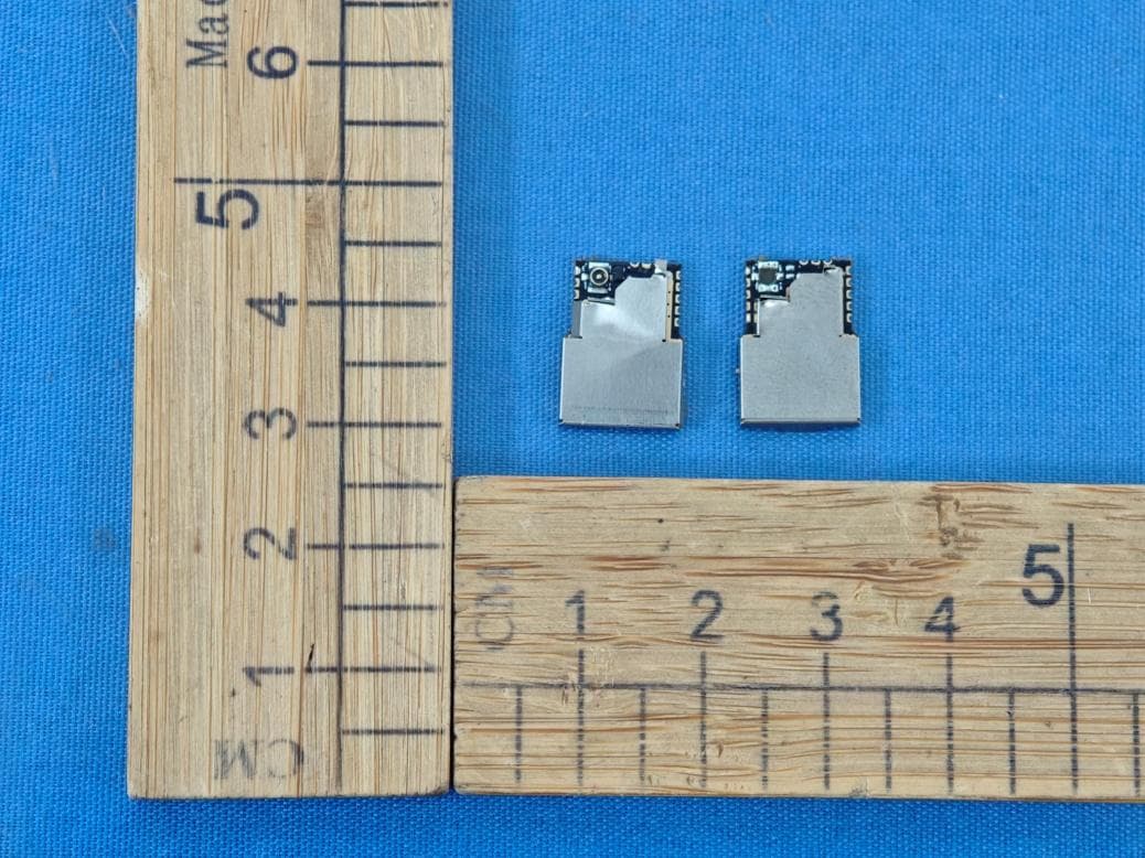
Click to zoom
Application Details
- Equipment Class
- DTS - Digital Transmission System
- Date of Grant
- Mar 12, 2026
- Application Purpose
- Original Equipment
- Equipment Note
- M5Stamp LoRa-1262
- Frequency Range
- 903.00000000 - 914.90000000
- Company
- M5Stack Technology Co.,Ltd
- Country
- China
Documents & Files
Document Text
Text extracted from the exhibit documents filed with the FCC. Open a document above to read the original.
Users Manual
Company Name:M5Stack Technology Co.,Ltd Address: Block A10, Expo Bay South Coast, Fuhai Street, Bao'an District, Shenzhen,Guangdong,China Stamp LoRa-1262 Company Name:M5Stack Technology Co.,Ltd Address: Block A10, Expo Bay South Coast, Fuhai Street, Bao'an District, Shenzhen,Guangdong,China 1. Description Stamp LoRa-1262 is an ultra-compact embedded LoRa communication module featuring a high-performance SX1262 LoRa transceiver, operating over the 868–923 MHz frequency band. Despite its miniature size, the module delivers powerful performance and maintains stable and reliable RF characteristics, even under complex and rapidly changing environmental conditions. Allow users to select a combination of PCB-outlet antenna connectors to meet specific application requirements. This flexibility makes Stamp LoRa-1262 easy to integrate into hardware designs of various sizes and form factors, and well suited for IoT, remote monitoring, and low-power wireless applications. Company Name:M5Stack Technology Co.,Ltd Address: Block A10, Expo Bay South Coast, Fuhai Street, Bao'an District, Shenzhen,Guangdong,China 2. Specifications Specification Parameters LoRa Module SX1262 LoRa Frequency Range For CE 868.100MHz-868.500MHz Transmit Maximum ERP For CE LoRa: 10.52dBm LoRa Programmable Bit Rate Up to 300kbps LoRa Communication Interface SPI LoRa Receiver Sensitivity –147 dBm (LoRa low data rate mode) Supported Modulation Modes CSS Antenna Type: Dipole Antenna Receiver category The equipment provider declared that the receiver category for the EUT is 2 Hardware version NO. V1.0 Software version NO. V1.0 3. Quick Start 3.1 LoRa TX Allow users to control the device via SPI by drawing wires or flying leads on the board. Company Name:M5Stack Technology Co.,Ltd Address: Block A10, Expo Bay South Coast, Fuhai Street, Bao'an District, Shenzhen,Guangdong,China 4. FCC Warning FCC Caution: Any Changes or modifications not expressly approved by the party responsible for compliance could void the user's authority to operate the equipment. This device complies with part 15 of the FCC Rules. Operation is subject to the following two conditions: (1) This device may not cause harmful interference, and (2) this device must accept any interference received, including interference that may cause undesired operation. IMPORTANT NOTE: Note: This equipment has been tested and found to comply with the limits for a Class B digital device, pursuant to part 15 of the FCC Rules. These limits are designed to provide reasonable protection against harmful interference in a residential installation. This equipment generates, uses and can radiate radio frequency energy and, if not installed and used in accordance with the instructions, may cause harmful interference to radio communications. However, there is no guarantee that interference will not occur in a particular installation. If this equipment does cause harmful interference to radio or television reception, which can be determined by turning the equipment off and on, the user is encouraged to try to correct the interference by one or more of the following measures: Reorient or relocate the receiving antenna. — Increase the separation between the equipment and receiver. — Connect the equipment into an outlet on a circuit different from that to which the receiver is connected. Consult the dealer or an experienced radio/TV technician for help. FCC Radiation Exposure Statement: This equipment complies with FCC radiation exposure limits set forth for an uncontrolled environment. This equipment should be installed and operated with minimum distance 20cm between the radiator& your body. Company Name:M5Stack Technology Co.,Ltd Address: Block A10, Expo Bay South Coast, Fuhai Street, Bao'an District, Shenzhen,Guangdong,China Integration instructions for host product manufacturers 2.1 General This document refers to FCC 996369 D03 OEM Manual v01r01, and lists the requirements for module integrators. 2.2 List of applicable FCC rules CFR 47 FCC PART 15 SUBPART C has been investigated. It is applicable to the modular. 2.3 Specific operational use conditions This module is stand-alone modular. If the end product will involve the Multiple simultaneously transmitting condition or different operational conditions for a stand-alone modular transmitter in a host, host manufacturer have to consult with module manufacturer for the installation method in end system. 2.4 Limited module procedures Not applicable. 2.5 Trace antenna designs Not applicable. 2.6 RF exposure considerations To maintain compliance with FCC’s RF Exposure guidelines, this equipment should be installed and operated with minimum distance of 20cm from your body. 2.7 Antennas The Lora antenna is dipole antenna, the antenna gain is 3.08dBi. 2.8 Label and compliance information The final end product must be labeled in a visible area with the following "Contains FCC ID: 2AN3WSTAMPLORA1262” 2.9 Information on test modes and additional testing requirements Host manufacturer is strongly recommended to confirm compliance with FCC requirements for the transmitter when the module is installed in the host. 2.10 Additional testing, Part 15 Subpart B disclaimer Host manufacturer is responsible for compliance of the host system with module installed with all other applicable requirements for the system such as Part 15 B. Company Name:M5Stack Technology Co.,Ltd Address: Block A10, Expo Bay South Coast, Fuhai Street, Bao'an District, Shenzhen,Guangdong,China FOR CE Conformity Assessment of the Radio Module to the RED This radio module is for professional installation only. When installing this radio module permanently into a host product to a create new radio equipment device; the manufacturer responsible for placing the final radio product on the market in the EU must assess if the combination of this radio module and the host product complies with the essential requirements of the RE Directive 2014/53/EU. Firmware version: v2.3 Test Antenna: dipole a…
Text truncated - open the document above for the full version.
Users Manual
Company Name:M5Stack Technology Co.,Ltd Address: Block A10, Expo Bay South Coast, Fuhai Street, Bao'an District, Shenzhen,Guangdong,China Stamp LoRa-1262 IF Company Name:M5Stack Technology Co.,Ltd Address: Block A10, Expo Bay South Coast, Fuhai Street, Bao'an District, Shenzhen,Guangdong,China 1. Description Stamp LoRa-1262 IF is an ultra-compact embedded LoRa communication module featuring a high-performance SX1262 LoRa transceiver, operating over the 868–923 MHz frequency band. Despite its miniature size, the module delivers powerful performance and maintains stable and reliable RF characteristics, even under complex and rapidly changing environmental conditions. Multiple variants are available, allowing users to select different combinations of pre- mounted IPEX-4 antenna connectors and 0.5 mm @ 12P FPC connectors (for module communication I/O breakout) to suit specific application requirements. This flexibility makes Stamp LoRa-1262 IF easy to integrate into hardware designs of various sizes and form factors, and well suited for IoT, remote monitoring, and low-power wireless applications. Company Name:M5Stack Technology Co.,Ltd Address: Block A10, Expo Bay South Coast, Fuhai Street, Bao'an District, Shenzhen,Guangdong,China 2. Specifications Specification Parameters LoRa Module SX1262 LoRa Frequency Range For CE 868.100MHz-868.500MHz Transmit Maximum ERP For CE LoRa: 10.52dBm LoRa Programmable Bit Rate Up to 300kbps LoRa Communication Interface SPI LoRa Receiver Sensitivity –147 dBm (LoRa low data rate mode) Supported Modulation Modes CSS IPEX Connector Type IPEX-4 FPC Connector Type 0.5 mm @ 12P Antenna Type: Dipole Antenna Receiver category The equipment provider declared that the receiver category for the EUT is 2 Hardware version NO. V1.0 Software version NO. V1.0 Company Name:M5Stack Technology Co.,Ltd Address: Block A10, Expo Bay South Coast, Fuhai Street, Bao'an District, Shenzhen,Guangdong,China 3. Quick Start 3.1 LoRa TX The user connects to the Basic host via FPC, controls the device through SPI, and burns the test firmware for testing. Company Name:M5Stack Technology Co.,Ltd Address: Block A10, Expo Bay South Coast, Fuhai Street, Bao'an District, Shenzhen,Guangdong,China 4. FCC Warning FCC Caution: Any Changes or modifications not expressly approved by the party responsible for compliance could void the user's authority to operate the equipment. This device complies with part 15 of the FCC Rules. Operation is subject to the following two conditions: (1) This device may not cause harmful interference, and (2) this device must accept any interference received, including interference that may cause undesired operation. IMPORTANT NOTE: Note: This equipment has been tested and found to comply with the limits for a Class B digital device, pursuant to part 15 of the FCC Rules. These limits are designed to provide reasonable protection against harmful interference in a residential installation. This equipment generates, uses and can radiate radio frequency energy and, if not installed and used in accordance with the instructions, may cause harmful interference to radio communications. However, there is no guarantee that interference will not occur in a particular installation. If this equipment does cause harmful interference to radio or television reception, which can be determined by turning the equipment off and on, the user is encouraged to try to correct the interference by one or more of the following measures: Reorient or relocate the receiving antenna. — Increase the separation between the equipment and receiver. — Connect the equipment into an outlet on a circuit different from that to which the receiver is connected. Consult the dealer or an experienced radio/TV technician for help. FCC Radiation Exposure Statement: This equipment complies with FCC radiation exposure limits set forth for an uncontrolled environment. This equipment should be installed and operated with minimum distance 20cm between the radiator& your body. Company Name:M5Stack Technology Co.,Ltd Address: Block A10, Expo Bay South Coast, Fuhai Street, Bao'an District, Shenzhen,Guangdong,China Integration instructions for host product manufacturers 2.1 General This document refers to FCC 996369 D03 OEM Manual v01r01, and lists the requirements for module integrators. 2.2 List of applicable FCC rules CFR 47 FCC PART 15 SUBPART C has been investigated. It is applicable to the modular. 2.3 Specific operational use conditions This module is stand-alone modular. If the end product will involve the Multiple simultaneously transmitting condition or different operational conditions for a stand-alone modular transmitter in a host, host manufacturer have to consult with module manufacturer for the installation method in end system. 2.4 Limited module procedures Not applicable. 2.5 Trace antenna designs Not applicable. 2.6 RF exposure considerations To maintain compliance with FCC’s RF Exposure guidelines, this equipment should be installed and operated with minimum distance of 20cm from your body. 2.7 Antennas The Lora antenna is dipole antenna with I-PEX4 connector, the antenna gain is 3.08dBi. 2.8 Label and compliance information The final end product must be labeled in a visible area with the following "Contains FCC ID: 2AN3WSTAMPLORA1262” 2.9 Information on test modes and additional testing requirements Host manufacturer is strongly recommended to confirm compliance with FCC requirements for the transmitter when the module is installed in the host. 2.10 Additional testing, Part 15 Subpart B disclaimer Host manufacturer is responsible for compliance of the host system with module installed with all other applicable requirements for the system such as Part 15 B. Company Name:M5Stack Technology Co.,Ltd Address: Block A10, Expo Bay South Coast, Fuhai Street, Bao'an District, Shenzhen,Guangdong,China FOR CE Conformity Assessment of the Radio Module to the RED This radio module is for professional installation only. Wh…
Text truncated - open the document above for the full version.
Users Manual
Company Name:M5Stack Technology Co.,Ltd Address: Block A10, Expo Bay South Coast, Fuhai Street, Bao'an District, Shenzhen,Guangdong,China Stamp LoRa-1262 I Company Name:M5Stack Technology Co.,Ltd Address: Block A10, Expo Bay South Coast, Fuhai Street, Bao'an District, Shenzhen,Guangdong,China 1. Description Stamp LoRa-1262 I is an ultra-compact embedded LoRa communication module featuring a high-performance SX1262 LoRa transceiver, operating over the 868–923 MHz frequency band. Despite its miniature size, the module delivers powerful performance and maintains stable and reliable RF characteristics, even under complex and rapidly changing environmental conditions. Allowing users to select different combinations of pre mounted IPEX-4 antenna connectors to suit specific application requirements. This flexibility makes Stamp LoRa-1262 I easy to integrate into hardware designs of various sizes and form factors, and well suited for IoT, remote monitoring, and low-power wireless applications. Company Name:M5Stack Technology Co.,Ltd Address: Block A10, Expo Bay South Coast, Fuhai Street, Bao'an District, Shenzhen,Guangdong,China 2. Specifications Specification Parameters LoRa Module SX1262 LoRa Frequency Range For CE 868.100MHz-868.500MHz Transmit Maximum ERP For CE LoRa: 10.52dBm LoRa Programmable Bit Rate Up to 300kbps LoRa Communication Interface SPI LoRa Receiver Sensitivity –147 dBm (LoRa low data rate mode) Supported Modulation Modes CSS IPEX Connector Type IPEX-4 Antenna Type: Dipole Antenna Receiver category The equipment provider declared that the receiver category for the EUT is 2 Hardware version NO. V1.0 Software version NO. V1.0 3. Quick Start 3.1 LoRa TX Allow users to control the device via SPI by drawing wires or flying leads on the board. Company Name:M5Stack Technology Co.,Ltd Address: Block A10, Expo Bay South Coast, Fuhai Street, Bao'an District, Shenzhen,Guangdong,China 4. FCC Warning FCC Caution: Any Changes or modifications not expressly approved by the party responsible for compliance could void the user's authority to operate the equipment. This device complies with part 15 of the FCC Rules. Operation is subject to the following two conditions: (1) This device may not cause harmful interference, and (2) this device must accept any interference received, including interference that may cause undesired operation. IMPORTANT NOTE: Note: This equipment has been tested and found to comply with the limits for a Class B digital device, pursuant to part 15 of the FCC Rules. These limits are designed to provide reasonable protection against harmful interference in a residential installation. This equipment generates, uses and can radiate radio frequency energy and, if not installed and used in accordance with the instructions, may cause harmful interference to radio communications. However, there is no guarantee that interference will not occur in a particular installation. If this equipment does cause harmful interference to radio or television reception, which can be determined by turning the equipment off and on, the user is encouraged to try to correct the interference by one or more of the following measures: Reorient or relocate the receiving antenna. — Increase the separation between the equipment and receiver. — Connect the equipment into an outlet on a circuit different from that to which the receiver is connected. Consult the dealer or an experienced radio/TV technician for help. FCC Radiation Exposure Statement: This equipment complies with FCC radiation exposure limits set forth for an uncontrolled environment. This equipment should be installed and operated with minimum distance 20cm between the radiator& your body. Company Name:M5Stack Technology Co.,Ltd Address: Block A10, Expo Bay South Coast, Fuhai Street, Bao'an District, Shenzhen,Guangdong,China Integration instructions for host product manufacturers 2.1 General This document refers to FCC 996369 D03 OEM Manual v01r01, and lists the requirements for module integrators. 2.2 List of applicable FCC rules CFR 47 FCC PART 15 SUBPART C has been investigated. It is applicable to the modular. 2.3 Specific operational use conditions This module is stand-alone modular. If the end product will involve the Multiple simultaneously transmitting condition or different operational conditions for a stand-alone modular transmitter in a host, host manufacturer have to consult with module manufacturer for the installation method in end system. 2.4 Limited module procedures Not applicable. 2.5 Trace antenna designs Not applicable. 2.6 RF exposure considerations To maintain compliance with FCC’s RF Exposure guidelines, this equipment should be installed and operated with minimum distance of 20cm from your body. 2.7 Antennas The Lora antenna is dipole antenna with I-PEX4 connector, the antenna gain is 3.08dBi. 2.8 Label and compliance information The final end product must be labeled in a visible area with the following "Contains FCC ID: 2AN3WSTAMPLORA1262” 2.9 Information on test modes and additional testing requirements Host manufacturer is strongly recommended to confirm compliance with FCC requirements for the transmitter when the module is installed in the host. 2.10 Additional testing, Part 15 Subpart B disclaimer Host manufacturer is responsible for compliance of the host system with module installed with all other applicable requirements for the system such as Part 15 B. Company Name:M5Stack Technology Co.,Ltd Address: Block A10, Expo Bay South Coast, Fuhai Street, Bao'an District, Shenzhen,Guangdong,China FOR CE Conformity Assessment of the Radio Module to the RED This radio module is for professional installation only. When installing this radio module permanently into a host product to a create new radio equipment device; the manufacturer responsible for placing the final radio product on the market in the EU must assess if the combination of this radio module and the host product complies with the essential requirements of…
Text truncated - open the document above for the full version.
ID Label/Location Info
Stamp LoRa-1262 I Label Label location Stamp LoRa-1262 IF Label Label location Stamp LoRa-1262 Label Label location
Test Setup Photos
Shenzhen Accurate Technology Co., Ltd. No.: 2604P13970E-RF Test Photos Test Photos Page 1 / 3 Photo of Power Line Conducted Emission Measurement Shenzhen Accurate Technology Co., Ltd. No.: 2604P13970E-RF Test Photos Test Photos Page 2 / 3 Radiated Spurious Emissions Test View (9kHz-30MHz) Radiated Spurious Emissions Test View (30MHz-1GHz) Shenzhen Accurate Technology Co., Ltd. No.: 2604P13970E-RF Test Photos Test Photos Page 3 / 3 Radiated Spurious Emissions Test View (Above 1GHz) ***** END *****
Test Report
Note: This report must not be used by the customer to claim product certification, approval, or endorsement by A2LA, or any agency of the Federal Government. The information marked ―#‖ is provided by the applicant, the laboratory is not responsible for its authenticity and this information can affect the validity of the result in the test report. Customer model name, addresses, names, trademarks etc. are included but no need marked. This report cannot be reproduced except in full, without prior written approval of the Company. Unless otherwise stated the results shown in this test report refer only to the sample(s) tested. This report is valid only with a valid digital signature. The digital signature may be available only under the Adobe software above version 7.0. Shenzhen Accurate Technology Co., Ltd. Floor 1, KuMaKe Building, Dongzhou Community, Guangming Street, Guangming District, Shenzhen, Guangdong, China. Tel: +86 755-26503290 Web: www.atc-lab.com Rev:A/4.0(2024/11/01) Page 1 of 57 TR-4-E-R018 TEST REPORT Applicant Name: M5Stack Technology Co., Ltd Address: Block A10, Expo Bay South Coast, Fuhai Street, Bao'an District, Shenzhen, Guangdong, China Report Number: 2604P13970E-RF-00A FCC ID: 2AN3WSTAMPLORA1262 Test Standard (s) FCC PART 15.247 Sample Description Product Name: M5Stamp LoRa-1262 Model No.: Stamp LoRa-1262 IF, Stamp LoRa-1262, Stamp LoRa-1262 I Trade Mark: Date Received: 2026-01-19 Report Date: 2026-03-05 Test Result: The EUT complied with the standards above. Prepared and Checked By: Approved By: Jason Fan Bob.Liao EMC Engineer EMC Engineer Shenzhen Accurate Technology Co., Ltd. Report No.: 2604P13970E-RF-00A Rev:A/4.0(2024/11/01) Page 2 of 57 TR-4-E-R018 TABLE OF CONTENTS DOCUMENT REVISION HISTORY ................................................................................................................ 4 GENERAL INFORMATION ............................................................................................................................ 5 PRODUCT DESCRIPTION FOR EQUIPMENT UNDER TEST (EUT) ........................................................................ 5 OBJECTIVE ................................................................................................................................................... 5 TEST METHODOLOGY .................................................................................................................................... 5 TEST FACILITY .............................................................................................................................................. 6 MEASUREMENT UNCERTAINTY ....................................................................................................................... 6 SYSTEM TEST CONFIGURATION ............................................................................................................... 7 DESCRIPTION OF TEST CONFIGURATION......................................................................................................... 7 EUT EXERCISE SOFTWARE AND POWER LEVEL # ............................................................................................ 7 SPECIAL ACCESSORIES AND EQUIPMENT MODIFICATIONS ............................................................................... 7 SUPPORT EQUIPMENT LIST AND DETAILS ....................................................................................................... 7 EXTERNAL I/O CABLE .................................................................................................................................... 7 BLOCK DIAGRAM OF TEST SETUP .................................................................................................................. 8 SUMMARY OF TEST RESULTS ................................................................................................................. 10 TEST EQUIPMENT LIST ............................................................................................................................. 11 ANTENNA REQUIREMENT......................................................................................................................... 12 APPLICABLE STANDARD ............................................................................................................................... 12 ANTENNA CONNECTOR CONSTRUCTION ....................................................................................................... 12 AC LINE CONDUCTED EMISSIONS .......................................................................................................... 13 APPLICABLE STANDARD ............................................................................................................................... 13 EUT SETUP ................................................................................................................................................ 13 EMI TEST RECEIVER SETUP ........................................................................................................................ 13 TEST PROCEDURE ...................................................................................................................................... 13 CALCULATION ............................................................................................................................................. 14 TEST DATA ................................................................................................................................................. 14 RADIATED SPURIOUS EMISSIONS .......................................................................................................... 17 APPLICABLE STANDARD ............................................................................................................................... 17 EUT SETUP ................................................................................................................................................ 17 EMI TEST RECEIVER & SPECTRU…
Text truncated - open the document above for the full version.
Test Report
Date11/21/2021Version No.V2.0 深圳市榕盛源科技有限公司科技有限公司 Shenzhen RSYElectronic Technology Co., Ltd 产品规格书 PRODUCTSPECIFICATION 1 Company Name:Shenzhen RSYElectronic Technology Co., Ltd Adress::703, No. 55 Ainan Road, Longdong Community, Baolong Street, Longgang District, Shenzhen 客户 Customer M5 客户编码 Customer’s part number 产品料号 Product Material Code RSY-E5018 工作频段 Working Band 868/915MHz 发行日期 Issue Date 2025-11-21 发行版本 Release Version V2.0 作者 Author Yang Ye Date11/21/2021Version No.V2.0 1产品技术指标(PRODUCT TECHNICALSPECIFICATION) 2产品电性能参数(PRODUCT ELECTRICAL PERFORMANCE PARAMETER) 1.产品图片(Product picture) 产品名称 NameLora天线型号 Model TypeRSY-E5018 频率范围 Frenquency Range 868-915MHZ尺寸 Dimensions108±2mm 驻波比 VSWR <2.5 连接器型号 ConnectorSMA 平均增益 Gain≧3 dBi 外壳材料 Radome Material TPEE 输入阻抗Impedance50Ω 外壳颜色 Radome Color Black 极化方式 Polarization polarizatio Verticaln 电缆型号/高度 Cable Length 辐射方向 RadiatonOmnidirectional 工作温度 Working Temperature -40°C- +80°C 2 Company Name:Shenzhen RSYElectronic Technology Co., Ltd Adress::703, No. 55 Ainan Road, Longdong Community, Baolong Street, Longgang District, Shenzhen R P - Date11/21/2021Version No.V2.0 2.3驻波比(VSWR) 2.2反射损耗(S11) * Company Name:Shenzhen RSYElectronic Technology Co., Ltd Adress::703, No. 55 Ainan Road, Longdong Community, Baolong Street, Longgang District, Shenzhen Date11/21/2021Version No.V2.0 2.5 效率、增益(Efficiency/Gain) 2.4史密斯图(Smith Chart) 4 Company Name:Shenzhen RSYElectronic Technology Co., Ltd Adress::703, No. 55 Ainan Road, Longdong Community, Baolong Street, Longgang District, Shenzhen Fre.(MHz)Gain.(dBi)Eff.(%) 8602.8951.38 8703.5455.72 8803.3872.75 8902.866.13 9003.0662.17 9103.0861.9 9202.1461.09 9302.3760.24 Date11/21/2021Version No.V2.0 2.6辐射方向图(Radiation Pattern) 5 Company Name:Shenzhen RSYElectronic Technology Co., Ltd Adress::703, No. 55 Ainan Road, Longdong Community, Baolong Street, Longgang District, Shenzhen 868MHz 915MHz Date11/21/2021Version No.V2.0 3产品尺寸(Product dimensions) 6 Company Name:Shenzhen RSYElectronic Technology Co., Ltd Adress::703, No. 55 Ainan Road, Longdong Community, Baolong Street, Longgang District, Shenzhen
RF Exposure Info
Note: This report must not be used by the customer to claim product certification, approval, or endorsement by A2LA, or any agency of the Federal Government. The information marked “#” is provided by the applicant, the laboratory is not responsible for its authenticity and this information can affect the validity of the result in the test report. Customer model name, addresses, names, trademarks etc. are included but no need marked. This report cannot be reproduced except in full, without prior written approval of the Company. Unless otherwise stated the results shown in this test report refer only to the sample(s) tested. This report is valid only with a valid digital signature. The digital signature may be available only under the Adobe software above version 7.0. Shenzhen Accurate Technology Co., Ltd. Floor 1, KuMaKe Building, Dongzhou Community, Guangming Street, Guangming District, Shenzhen, Guangdong, China. Tel: +86 755-26503290 Web: www.atc-lab.com Rev:A/4.0(2024/11/01) Page 1 of 6 TR-4-E-R052 TEST REPORT Applicant Name : M5Stack Technology Co., Ltd Address : Block A10, Expo Bay South Coast, Fuhai Street, Bao'an District, Shenzhen,Guangdong, China Report Number : 2604P13970E-RF FCC ID: 2AN3WSTAMPLORA1262 Test Standard (s) 47 CFR §2.1091 Sample Description Product Type: M5Stamp LoRa-1262 Model No.: Stamp LoRa-1262 IF, Stamp LoRa-1262, Stamp LoRa-1262 I Trade Mark: Date Received: 2026-01-19 Report Date: 2026-03-05 Test Result: The EUT complied with the standards above. Prepared and Checked By: Approved By: Jason Fan Bob.Liao EMC Engineer EMC Engineer Shenzhen Accurate Technology Co., Ltd. Report No.: 2604P13970E-RF Rev:A/4.0(2024/11/01) Page 2 of 6 TR-4-E-R052 TABLE OF CONTENTS DOCUMENT REVISION HISTORY ................................................................................................................ 3 GENERAL INFORMATION ............................................................................................................................ 4 PRODUCT DESCRIPTION FOR EQUIPMENT UNDER TEST (EUT) ........................................................................ 4 OBJECTIVE ................................................................................................................................................... 4 TEST FACILITY .............................................................................................................................................. 4 RF EXPOSURE .............................................................................................................................................. 5 APPLICABLE STANDARD ................................................................................................................................. 5 RESULT ........................................................................................................................................................ 5 EXHIBIT A-EUT PHOTOGRAPHS ................................................................................................................ 6 Shenzhen Accurate Technology Co., Ltd. Report No.: 2604P13970E-RF Rev:A/4.0(2024/11/01) Page 3 of 6 TR-4-E-R052 DOCUMENT REVISION HISTORY Revision Number Report Number Description of Revision Date of Revision Rev.00 2604P13970E…
Text truncated - open the document above for the full version.
Contact Information
Applicant
Jimmy Lai
[email protected]Fax: 0755-69815195
Technical Contact
Iconsigh Inc.Benjamin Kaur
2310 Homestead Road Suite C1 · Los Altos, California, 94024 · United States
Test Firm
Shenzhen Accurate Technology Co., Ltd.Hazel Li
Technical Specifications
| # | Rule Parts | Frequency Range | Power Output |
|---|---|---|---|
| 1 | 15C | 903 MHz - 914.9 MHz | 9.90 mW |