2AN6O-SDX30SmartDate X30
Markem-Imaje Industries Ltd.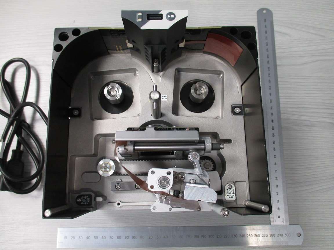
Click to zoom
Application Details
- Equipment Class
- DXX - Part 15 Low Power Communication Device Transmitter
- Date of Grant
- Sep 26, 2022
- Application Purpose
- Original Equipment
- Date of Application
- Sep 26, 2022
- Equipment Note
- SmartDate X30
- Frequency Range
- 13.56000000 - 13.56000000
- Company
- Markem-Imaje Industries Ltd.
- Country
- United Kingdom
Documents & Files
Document Text
Text extracted from the exhibit documents filed with the FCC. Open a document above to read the original.
Users Manual
Safety and important information EN2 Sécurité et informations importantes FR4 Información de seguridad e información importante ES6 Sicherheitsinformationen und wichtige Hinweise DE9 Informazioni sulla sicurezza e altre informazioni importanti IT11 Informações Importantes e Sobre Segurança PT14 Veiligheidsinformatie en belangrijke informatie NL16 Information om säkerhet och annan viktig information SV18 Sigurnost i važne informacije HR21 Turvallisuus ja tärkeitä tietoja FI23 Sikkerhedsoplysninger og vigtige oplysninger DA25 Biztonsági és fontos tudnivalók HU27 Informacje o bezpieczeństwie i ważne uwagi PL30 Informacije o varnosti in pomembne informacije SL32 Informace o bezpečnosti a důležitá sdělení CS34 Πληροφορίες για την ασφάλεια και σημαντικές πληροφορίες EL37 Информация за безопасността и важна информация BG39 Informācija par drošību un cita svarīga informācija LV 42 Darbo saugos ir kita svarbi informacija LT44 Informácie o bezpečnosti a dôležité informácie SK46 Ohutusteave ja oluline teave ET48 Informații cu privire la siguranță şi alte informații importante RO50 Sikkerhetsinformasjon og viktig informasjon NO 53 Güvenlik ve Önemli Bilgiler TR55 Безопасность и важная информация RU57 安全和重要信息 ZH60 ข้้อมููลเพื่่�อความูปลอดภััยและข้้อมููลสำ ํา าคัญ TH62 안전 및 유의사항 KO64 الأمان والمعلومات الهامةAR66 בטיחות ומידע חשובHE68 SmartDate X30 FR Retrouvez l'ensemble de la documentation de votre produit sur notre site internet en utilisant le code QR ou l'adresse www. markem-imaje.com EN Find all of your product’s documentation on our website by scanning the QR code or by visiting www.markem-imaje.com ES Consulte toda la documentación del pro- ducto en nuestro sitio de internet con el có- digo QR o en la dirección www.markem- imaje.com ZH 您可以扫描封面的二维码在我们官网浏览 您所购买产品的所有相关文件,或直接访 问 www.markem-imaje.com 进行浏览。 2 10073508 - AI EN Keep this information to hand so you can refer back to it at a later date. ■ Important note Find all of your product’s documentation on our website by scanning the QR code on the cover or by visiting www.markem-imaje.com. ■ Safety Before using this printer, please read and fully comply with these instructions, the safety data sheet (SDS) for consumables used and safety labels affixed to the printer. Servicing must be performed only by appropriately trained personel. ■ Liability Markem-Imaje shall not be liable for any damage or injury resulting from any failure to follow these safety instructions, as well as good manufacturing practices and safety standards that are generally applicable in the industry, when installing, using or servicing Markem-Imaje equipment. Any user who modifies or repairs Markem-Imaje equipment, uses consumables, spare parts or accessories other than those supplied by Markem- Imaje, or fails to comply with Markem-Imaje specifications shall have sole responsibility for the consequences thereof. Markem-Imaje shall not be liable for any malfunction or damage caused by any modification of the equipment or use of the equipment for any purposes other than those for which it is designed. The user shall be solely responsible for taking any precautions required by any use to which the user puts the Markem-Imaje equipment. Markem-Imaje consumables (ribbons, cleaning products and other consumables), spare parts and accessories are designed for use with Markem- Imaje equipment. Use of consumables, spare parts or accessories, that are not produced or recommended by Markem-Imaje for use with the specific Markem- Imaje equipment may harm the equipment and cause performance failures. Because Markem-Imaje equipment is tested with Markem-Imaje consumables and spare parts for conformity with certain regulations and safety standards, use of non-Markem-Imaje consumables and spare parts also may be inconsistent with testing conditions and affect compliance of the equipment with certain standards. The user shall bear all risks associated with use of unsuitable consumables and spare parts. This equipment is certified in accordance with the requirements for CE marking. ■ Health / Hygiene / Environment Max. noise level< 70 dbA Operating temperature 0° C to 40° C (32° F to 104° F) Humidity 0 - 90% RH with no condensation ■ Handling When removing the printer from the host machine, care should be taken to first ensure that the body of the printer is at a temperature that can be comfortably handled. It is important to note that the rear of the printer is likely to be the warmest zone and warrants particular attention. Safety shoes should be worn when installing or removing the Printer body from packaging machinery. These units are heavy and there is a danger of injury if dropped. To avoid injury by dropping the ribbon cassette when changing ribbon, please ensure the ribbon cassette is placed on a bench and that safety shoes are worn. Printer weight5.9Kg ■ Installation Installations are normally performed by qualified Markem-Imaje service technicians or approved distributors. Installations not performed by Markem- Imaje service technicians or distributors must be performed by competent personel in accordance with the applicable local regulations. Seek advice from your Markem-Imaje representitive if you are in any doubt. ■ Installation Requirements Ensure that these services and control signals are available: Power - 100-230V AC (+/- 10%) 50-60 Hz. A disconnect device (plug or other device) should be located close to the SmartDate Controller and be easily accessible at all times. A protective earthing conductor shall be connected to the installation protective earthing conductor (for example, by means of the supplied power cord, connected to a socket-outlet with earthing connection). 10073508 - AI 3 English A 'Print Go' signal - This can be either a volt free contact which closes when printing is required or a 24 V DC signal from a PNP sensor (positive edge triggered). Sufficient space for installation and operation. In addition, SmartDate X30 continuous printer requires an encoder to mo…
Text truncated - open the document above for the full version.
Users Manual
132 465 798 0 Instruction manual Printer overview Local user interface Start/Stop the printer Selecting a job Menu Printhead maintenance Consumables Troubleshooting - Information Instruction manual Printer overview 2 1Printer 2Ribbon Cassette 3Detachable Hand-held terminal (HHT) 4Hand-held terminal USB connecting cable ■Printer Components 12 34 Instruction manual Printer overview 3 SmartDate X30 Continuous SmartDate X30 Intermittent ■Printer Type Instruction manual Power connection 4 ■Connecting the Power Power On Power Off Instruction manual Printer status 5 Producing Not Producing/Fault Warning Busy 132 465 798 0 Instruction manual Local user interface 132 465 798 0 i Producing Job: 20 105 Menu Stop LCD Display Numeric Keypad Insert Space Screen Contrast Navigation Buttons Top Quad Left Button Right Button Bottom Quad Left QuadRight Quad 6 Instruction manual Printer Start/Stop i 132 465 798 0 i Ready Job: 20 105 MenuStart 132 465 798 0 i Producing Job: 20 105 MenuStop OR OR 7 ■ Starting the Printer ■ Stopping the Printer Safety Instruction manual Selecting a job 8 1 132 465 798 0 i Producing Job: 20 105 MenuStop 132 465 798 0 i Field 1 User Text xxxx Back Select 132 465 798 0 i Back Select 02 Print Adjust 01 Select Job 03 Engineering 132 465 798 0 i 02 Job 2 01 Job 1 03 Job 3 Back Select 2 34 ■Using the Smartdate X30 Database Safety Instruction manual Selecting a job 9 ■ Using a USB Memory Stick Database Note: The SmartDate X30 must be configured to use the USB memory stick database. Insert the USB memory stick into the hand-held terminal and select a job following the same procedure as above. 56 132 465 798 0 i Confirm Job Select? Job 1 Cancel Confirm 132 465 798 0 i Field 1 User Text xxxx Back Select Safety Instruction manual Selecting a job 10 ■Using CoLOS Job Database Note: The SmartDate X30 must be configured to use the CoLOS job database. 12 34 132 465 798 0 i Producing Job: 20 105 MenuStop 132 465 798 0 i Back Select Job 1 Input Job Name 132 465 798 0 i Field 1 User Text xxxx Back Select 132 465 798 0 i Back Select 02 Print Adjust 01 Select Job 03 Engineering Safety Instruction manual Selecting a job 11 5 132 465 798 0 i Confirm Job Select? Job 1 Cancel Confirm Safety Instruction manual Printer menus 12 Solenoid On Hours Menu Select job Print Adjust Engineering Darkness Registration Offset Rotation Test Print Settings Diagnostics Service File Management Statistics Values Test Image Manual Control Reset Counts Factory Reset Clone Restore Upgrade MTBF Count HHT Insertions P/H Count Ribbon Count Copy to Printer Copy to USB Save Logs Clear Database Delete Job Language Communications Time Date Machine Flex IO Record Profile Safety Instruction manual Printer menus Cleaning the Printhead 13 Clean the printhead regularly using Markem-Imaje printhead wipes. Remove the cassette and allow the printhead to cool to normal room temperature. Use a Markem-Imaje printhead cleaning wipe to remove any residue from the printhead as shown. Do not use abrasive materials or tools such as screwdrivers or knifes to clean the printhead. 1 2 Safety Instruction manual Changing the ribbon 1 2 14 Opening the cassette Do not use force or tools if the latch does not turn. Remove the used ribbon. Safety Instruction manual Changing the ribbon Markem-Imaje ribbon only Ribbon Path Left Hand Cassette Right Hand Cassette 15 Safety Instruction manual Changing the ribbon Loading the new ribbon (LH cassette shown) 3 3a3b 3c3d 16 Safety Instruction manual Faults and Warnings 17 ■Faults Hide Fault 1109 Calibration Failure Please open and close the cassette A fault will stop the printer. The fault causing the condition must be fixed before printing can continue. ■Warnings Hide Warning 2103 Cropped print Contents of image does not fit within A warning does not stop the printer imediately but does indicate a condition that may require attention. the image area www.markem-imaje.com Instruction manual Faults and Warnings 18 ■Common Faults and Warnings LOW RIBBON The ribbon will soon run out, prepare a new ribbon. CASSETTE OPEN The cassette latch is open, close it. CALIBRATION FAILED The ribbon has broken during calibration, reload the ribbon and try again. RIBBON BREAK DETECTED The ribbon has broken during printing reload the ribbon. Safety Instruction manual Information 19 S/N: Serial number: Ribbon type: For Marking & Coding Equipment. Photographs and drawings are not binding in detail. This document was originally written in English. The English text of this document shall alone be authentic and shall prevail in the event of a dispute. Markem-Imaje reserves the right to modify the specifications of its products without prior notice. Any reproduction, even partial, of this document is prohibited. Original manual. © 2019 Markem-Imaje All Rights Reserved. English version TSS - User Documentation Markem-Imaje Limited Nottingham Science Park University Boulevard Nottingham NG7 2QN UK www.markem-imaje.com 10082287-AB 01/2019 en
ID Label/Location Info
DOSSIER DE DEFINITION DEFINITION FILE SPECIFICATION D’ETIQUETTE CONFORMITE REGLEMENTAIRE REGULATORY COMPLIANCE LABEL SPECIFICATION Page 1/4 Model : SmartDate X30 (AC version) 10070870-TES-AG This document is owned by Markem-Imaje Industries and cannot be disclosed without written permission X: Wildcard character P / N : X X X X X X X X D e s c r i p t i o n : S m a r t D a t e X 3 0 x x x x x x x x x M o d e l /모델명/型號/ M o d e l o : S m a r t D a t e X 3 0 S / N : X X X X X X X X X X R-R-MI8-SDX30 Markem-Imaje IND LTD, NOTTINGHAM NG7 2QN, UK Manufacturer/公司(工廠)名稱 /公司(工廠)地址: QR M a n u f a c t u r e d /제조년월/出廠年份: Y Y Y Y M M C o u n t r y o f o r i g i n /제조국가/原產地/ o r i g e n: M a d e i n X X X E l e c t r i c a l R a t i n g /電氣輸入: 100-2 3 0 V A C | 5 0 / 6 0 H z | 2.2-1.1A T r a d e m a r k /제조자/品牌/ M a r c a : M A R K E M-I M A J E 기자재의 명칭: R F I D / U S N용 무선기기 ( 1 3 . 5 6 M H z 대역 사용 기기) MARKING AND CODING EQUIPMENT Patent protected, see http://patents.markem-imaje.com/m4 HIDF18000269 08667-22-11483 CCAH20LPA430T1 H-23987 IFETEL : RCPMASD18-0837 Complies with IMDA Standards DA108100 5020795 Conforms to UL Std. 62368-1 Cert. to CSA Std. C22.2 No. 62368-1 CAN ICES-003(A) / NMB-003(A) C e n t e n a r y H o u s e , C e n t e n a r y W a y M a n c h e s t e r , M 5 0 1 R F , U K This device complies with part 15 of the FCC Rules. Operation is subject to the following two conditions: (1) This device may not cause harmful interference, and (2) this device must accept any interference received, including interference that may cause undesired operation. 10070870-TES-AG This document is owned by Markem-Imaje Industries and cannot be disclosed without written permission Regulatory Compliance Label Specification Page 2/4 Model: SmartDate X30 (AC version) LOGO Logo Requirements Certification Text Text Requirements Height ≥ 5mm Width (for the circle part of the logo) NRTL Conforms to UL Std. 62368-1 Cert. to CSA Std. C22.2 No. 62368-1 The text has to be big enough to be legible without magnification and must be located on the right of the Intertek logo. Height ≥ 5mm Width CE Height ≥ 7mm Width WEEE Height ≥ 5mm Width KC R-R-MI8-SDX30 The text has to be big enough to be legible without magnification. Height ≥ 5mm Width China National Deviation Height ≥ 6mm Width C-mim Height ≥ 5mm Width EAC This logo should be near to CE logo. Height ≥ 4mm Width ANATEL 08667-22-11483 The text has to be big enough to be legible without magnification and must be located under the ANATEL logo. Height ≥ 4 mm Width ENACOM H-23987 The text has to be big enough to be legible without magnification and must be located to the right of the R logo Arial font, Font size ≥ 5 5020795 10070870-TES-AG This document is owned by Markem-Imaje Industries and cannot be disclosed without written permission Regulatory Compliance Label Specification Page 3/4 Model: SmartDate X30 (AC version) Height ≥ 8mm Width ≥ 8mm SIRIM HIDF18000269 The text has to be big enough to be legible without magnification and must be located under the MCMC logo. IFETEL RCPMASD18-0837 The text has to be big enough to be legible without magnification. Height ≥ 9mm Width ≥ 17mm IMDA The text has to be big enough to be legible without magnification. Height ≥ 5mm Width NCC CCAH20LPA430T1 The text has to be big enough to be legible without magnification and must be located to the right of the NCC logo. Height ≥ 5mm Width UKCA C e n t e n a r y H o u s e , C e n t e n a r y W a y M a n c h e s t e r , M 5 0 1 R F , U K The text has to be big enough to be legible without magnification and must be located under the UKCA logo. No logo ICES-Gen ICES-003 CAN ICES-003(A) / NMB-003(A) The text has to be big enough to be legible without magnification. Height ≥ 3mm Width RCM No logo This device complies with part 15 of the FCC Rules. Operation is subject to the following two conditions: (1) This device may not cause harmful interference, and (2) this device must accept any interference received, including interference that may cause undesired operation The text has to be big enough to be legible without magnification FCC Radio FCC ID : XXXXXXXXX The text has to be big enough to be legible without magnification IC Radio IC : XXXXXX The text has to be big enough to be legible without magnification : Proportions must be kept 10070870-TES-AG This document is owned by Markem-Imaje Industries and cannot be disclosed without written permission Regulatory Compliance Label Specification Page 4/4 Model: SmartDate X30 (AC version) Revision History Dd/mm/yyyy D. Piech FCC ID, IC ID and FCC sentence added CRCO- ???? AG 24/06/2022 N. MOREIRA D.PIECH J. PALISSE ANATEL number and KC text update, CRCO-34200 AE 01/04/2022 Y. BENZAGGAGH D.PIECH J. PALISSE Addition of RCM logo to SmartDate X30 label CRCO-30999 AD 16/08/2021 Y. BENZAGGAGH D.PIECH J. PALISSE Correction of voltage and Reordering “manufactured” “country of origen” and “trademark” fields to harmonize TTO labels CRCO-17543 AC 4/06/2021 Y. BENZAGGAGH D.PIECH J. PALISSE Update of voltage format and addition of cETLus, ICES and UKCA markings CRCO-17543 AB 14/10/2020 Y. BENZAGGAGH D.PIECH J. PALISSE Label Specification STS creation CRCO-10190 AA Date Written by Checked by Approved by Description N° CR/CO REV
Operational Description
Page 1 of 10 V1.0 20/04/2022 Technical Specification Document No.: 10109298AF Product: X30 – SDX30 – RFID & Radio Antenna Details Assembly Number: Assembly number: RFID PCB - 10070580 RFID USB STATUS PCA 10070579 RFID USB STATUS PCB Document Revision History Rev. Date: Author Description AA 06/11/2017 Robert Gruszka First Issue AB 11/05/2018 Stephen Coats Added Block Diagrams for RFID Circuits AC 01/08/2018 Stephen Coats Added Frequency to block diagrams AD 12/04/2019 Robert Gruszka Added section with R and C changes AE 23/04/2019 Robert Gruszka Expanded section with R and C changes with side-by-side comparison AF 20/10/2020 Robert Gruszka Removed section 17 (components’ changes), Updated schematic screenshot and embedded documents: Schematic and BOM Page 2 of 10 V1.0 20/04/2022 Table of Contents 1 Introduction ................................................................................................................................................................ 3 2 General description ................................................................................................................................................... 3 3 Operational Description ............................................................................................................................................. 3 4 Power rails and voltage regulator .............................................................................................................................. 4 4.1 Power rails ......................................................................................................................................................... 4 4.2 Voltage regulator ............................................................................................................................................... 4 5 Microcontroller ........................................................................................................................................................... 5 6 RFID transceiver ........................................................................................................................................................ 5 7 RF Switch .................................................................................................................................................................. 5 8 USB channel .............................................................................................................................................................. 5 9 LED and switch signals transfer ................................................................................................................................ 5 10 EMC chassis/Earth connection ................................................................................................................................. 5 11 RF Block diagram ...................................................................................................................................................... 6 12 RF Schematic Diagram ............................................................................................................................................. 7 13 Assembly & BOM ...................................................................................................................................................... 7 14 RF PCBA Layout ....................................................................................................................................................... 8 15 Antenna Design ......................................................................................................................................................... 9 16 Antenna Connectors ................................................................................................................................................ 10 17 Component changes ................................................................................................. Error! Bookmark not defined. Page 3 of 10 V1.0 20/04/2022 1 Introduction This document is the technical description of the X30 RFID Radio circuits & antenna. It describes the technical aspects Radio circuit & antenna design and layout. This document is the technical description of the X30 RFID board. It describes the technical aspects of the PCB assembly and should be read in conjunction with the schematic for the PCB, document 10070581. 2 General description The X30 RFID PCB is a six-layer board with all of the functionality required to control the RFID functionality of the printer – Advance Consumable Management. In addition, the PCB provide additional functions: transfer through USB communication for external devices, LED, and switch signals to front membrane. Circuit comprises following sections: • Voltage regulator and power rails • Microcontroller • RFID transceiver • RF switch • USB channel • LED and switch signals transfer • EMC chassis/Earth connection 3 Operational Description An RFID tag is fitted to each ribbon waste spool and contains the set-up information of the ribbon as required by the printer. The printer reads the RFID tag during the calibration process and ‘pairs’ with the ribbon when a new ribbon is installed. The RFID is only read / write when new ribbon and only read during a calibration either when cassette is inserted OR when the power is turned on. The RFID radio frequency is 13.56MHz with a maximum power limit of 200mW (Limited by the TRF7960 IC) The radio signal is generated by TEXAS INSTRUMENT integrated circuit - TRF7960RHBT. It is provided to antenna through RF switch PEREGRINE SEMI - PE42440MLBB-Z. The RF system operates on single standard RFID system frequency at 13.56MHz. The power of the RF is limited to a maximum 200mW by the TEXAS INSTRUMENT integrated circuit - TRF7960RHBT. We use OOK modulation. But not in Direct Mode. It’s a software configuration. From TRF7960 datasheet: Modulator and SYS_CLK Register (0x09) to the…
Text truncated - open the document above for the full version.
Test Report
RF914 7.0 Report on the Radio Testing For Markem-Imaje Industries Limited on SmartDate X30 Report no. TRA-049942-45-00A 30th August 2022 RF914 7.0 REPORT ON THE RADIO TESTING OF A Markem-Imaje Industries Limited SmartDate X30 WITH RESPECT TO SPECIFICATION FCC 47CFR 15.225 TEST DATE: 2021-11-15 to 2022-06-09 Written by: Ian Broadwell Tested by: I. Broadwell and A. J. Longley Radio Test Engineers Approved by: D Winstanley Radio Senior Test Engineer Date: 30th August 2022 Disclaimers: [1] THIS DOCUMENT MAY BE REPRODUCED ONLY IN ITS ENTIRETY AND WITHOUT CHANGE [2] THE RESULTS CONTAINED IN THIS DOCUMENT RELATE ONLY TO THE ITEM(S) TESTED Report Number: TRA-049942-45-00A Issue: A Report Number: TRA-049942-45-00A RF914 7.0 Page 3 of 40 1 Revision Record Issue Number Issue Date Revision History A 30th August 2022 Original Report Number: TRA-049942-45-00A RF914 7.0 Page 4 of 40 2 Summary TEST REPORT NUMBER: TRA-049942-45-00A WORKS ORDER NUMBER: TRA-049942-02 PURPOSE OF TEST: USA: Testing of radio frequency equipment per the relevant authorization procedure of chapter 47 of CFR (code of federal regulations) Part 2, subpart J. TEST SPECIFICATION(S): 47CFR15.225 EQUIPMENT UNDER TEST (EUT): SmartDate X30 FCC IDENTIFIER: 2AN6O-SDX30 EUT SERIAL NUMBER: E321180461 MANUFACTURER/AGENT: Markem-Imaje Industries Limited ADDRESS: Nottingham Science & Technology Park University Boulevard Nottingham NG7 2QN CLIENT CONTACT: Dawid Piech 0115 9683 692 [email protected] ORDER NUMBER: PO: 4502018359 TEST DATE: 2021-11-15 to 2022-06-09 TESTED BY: I. Broadwell and A. J. Longley Element Report Number: TRA-049942-45-00A RF914 7.0 Page 5 of 40 2.1 Test Summary Test Method and Description Requirement Clause Applicable to this equipment Result / Note 47CFR15 Radiated spurious emissions, below 30 MHz 15.225(d) Pass Radiated spurious emissions 15.209 Pass AC power line conducted emissions 15.207 Pass Occupied bandwidth 15.215(c) Pass Field strength of fundamental 15.225(a), (b) and (c) Pass Frequency stability 15.225(e) Pass Notes: The results contained in this report relate only to the items tested, in the condition at time of test, and were obtained in the period between the date of initial receipt of samples and the date of issue of the report. The apparatus was set up and exercised using the configurations, modes of operation and arrangements defined in this report only. Any modifications made are identified in Section 8 of this report. Particular operating modes, apparatus monitoring methods and performance criteria required by the standards tested to have been performed except where identified in Section 5.2 of this test report (Deviations from Test Standards). Report Number: TRA-049942-45-00A RF914 7.0 Page 6 of 40 3 Contents 1 Revision Record ............................................................................................................................................... 3 2 Summary .......................................................................................................................................................... 4 2.1 Test Summary ......................................................................................................................................... 5 3 Contents ........................................................................................................................................................... 6 4 Introduction ....................................................................................................................................................... 8 5 Test Specifications ........................................................................................................................................... 9 5.1 Normative References ............................................................................................................................. 9 5.2 Deviations from Test Standards .............................................................................................................. 9 6 Glossary of Terms .......................................................................................................................................... 10 7 Equipment Under Test .................................................................................................................................... 11 7.1 EUT Identification .................................................................................................................................. 11 7.2 System Equipment ................................................................................................................................. 11 7.3 EUT Mode of Operation ......................................................................................................................... 11 7.4 EUT Radio Parameters .......................................................................................................................... 12 7.4.1 General .......................................................................................................................................... 12 7.4.2 Antennas ....................................................................................................................................... 12 7.5 EUT Description..................................................................................................................................... 12 8 Modifications ................................................................................................................................................... 13 9 EUT Test Setup .............................................................................................................................................. 14 9.1 Block Diagram ....................................................................................................................................... 14 9.2 General Set-up Photograph ......................................…
Text truncated - open the document above for the full version.
Contact Information
Applicant
Stephen Coats(Senior Engineer)
Test Firm
Element Materials Technology Warwick LtdNeil Roche
Technical Specifications
| # | Rule Parts | Frequency Range | Power Output |
|---|---|---|---|
| 1 | 15C | 13.56 MHz - 13.56 MHz | - |