2ANH2-P8LED Mini Projector
AAXA Technologies Inc
Click to zoom
Application Details
- Equipment Class
- DTS - Digital Transmission System
- Date of Grant
- Apr 14, 2022
- Application Purpose
- Original Equipment
- Date of Application
- Apr 13, 2022
- Equipment Note
- LED Mini Projector
- Frequency Range
- 2412.00000000 - 2462.00000000
- Company
- AAXA Technologies Inc
- Country
- United States
Documents & Files
Document Text
Text extracted from the exhibit documents filed with the FCC. Open a document above to read the original.
Users Manual
aaxa TECHNOLOGIES User Guide Wifi Bluetooth LED Mini Projector P8 Caution! WARNING: Please use this product as instructed. Misuse may cause injury or death. DO NOT use while driving DO NOT expose to water or wet surfaces. Electric shock may occur DO NOT expose the projected LED image to your eyes or the eyes of others DO NOT block or restrict airflow from ventilation holes as this may cause the projector to overheat Keep the projector, battery, or charger away from any heat sources Table of Contents Chapter 1: P8 at a Glance P8 Introduction Remote & KeypadRemote & Keypad Accessories Chapter 2: Getting Started Powering On / Off Focus Adjustment / Throw Distance Connecting to Speaker/ Headphone Loading External Content Chapter 3: Menu Screens Main Menu Brightness Menu *Wifi Menu *Mirroring Menu Streaming Services Menu Office Menu Files Menu Browser Menu Apps Menu *FAQ: Slideshow/ Zoom Connecting to Digital Input Chapter 4: Settings Menu Advanced Settings Language Settings Display Settings Keystone & Projection Direction *Bluetooth Menu Backup Reset Chapter 5: Technical Details Troubleshooting Specifications Notes 1 2 3 4 5 6 7 11 12 13 14 17 18 21 22 23 24 27 30 31 32 33 34 37 38 40 43 44 P8 at a Glance 1 Chapter 1 Digital AV (HDMI Compatible) Main Unit Focus Adjustment Micro SD TF Card Headphone Out Power On/Off 12V D/C Power Power Button USB-C Mirroring Type C Mirroring Standard USB 2.0 Compatible Remote & Keypad 2 Power On/Off Select Source MenuExit/Back Direction Pad Both the keypad and remote can be used to navigate through the menus. The Main Menu Navigation on the remote functions exactly the same as the directional pad on the P8 unit. Main Menu Navigation Media Player Menu Navigation Volume Up Volume Down Remote Keystone Adjustment Keystone Adjustment Accessories 3 *Under various circumstances, the actual accessories may be different from those shown in the pictures above. Additional accessories are available for purchase at www.aaxatech.com Power Adapter Remote Tripod Getting Started 1. Connect the power cord to the P8. 2. Connect the other end of the power cord into the wall power source. 3. Press the On/Off button at the back of the P8 for about 3 seconds, wait shortly and the projector should automatically boot up and turn on. 4 Powering ON the projector Chapter 2 Powering OFF the projector 1. To turn off the projector, press the “On/Off” button.This will fully turn off the projector. 2. Unplug and disconnect the P8 from the power source Focus Adjusment / Throw Distance 5 DIAGONAL SCREEN SIZE 16:9 Aspect Ratio Throw Distance Units: Inches 20 30 40 50 60 70 80 90 Diagonal Size Units: Inches 19 29 38 48 57 67 76 86 • Spin the focus wheel up or down until the image becomes clear. Focus Adjustment Throw Distance Chart Throw Ratio 1.20 Projection Angle: 100% Offset *minimum throw distance: 16 inches Connecting Speakers / Headphones Connect your speakers/headphones to the projector’s audio port. Step 1: Step 2: *CAUTION : Prolonged use of headphones at a high volume may impair hearing. Ensure that the projector and/or the headphones are powered on. Step 3: Place the headphones on and enjoy! 6 7 Loading External Content The P8 can read files directly from both a TF Card and USB Drive. Supported file types include: MP3 / WMA / OGG / WAV / AVI / MP4 / JPG / GIF PDF / DOC / XLS / PPT (up to 64 GB) (up to 64 GB) Loading External Content Cont. How to insert your TF Card • Slide in your TF card into the TF card slot on the side of the P8 (as shown in picture). • Gently slide the TF card until it clicks into place. 8 (up to 64 GB) Loading External Content Cont. How to insert your USB Drive • Slide your USB Drive into the USB port. • Gently slide the drive until it cannot go in any further. 9 (up to 64 GB) Loading External Content Cont. 10 Once your TF Card or USB Drive is inserted into the projector, the TF Card or USB Drive Storage will be loaded automatically and the content can be found through the Files icon on the Main Menu ( See Page 21 for File Viewer Sub- menu). To load Text documents, select the Office icon. ( See Page 19 to learn more) Menu Screens 11 Chapter 3 Main Menu The P8 features Android 10.0 Onboard and an Onboard Media Player. This function allows the projector to play videos, pictures, and music files directly from your connected devices. • Press the left and right directional buttons to choose an icon from the main menu. • To select a menu option, press the “OK” button in the middle of the navigation pad. • To go back to the previous screen, press the “Back” button. • To Jump back to the submenu, press the “Menu” button once. • To return to the main menu, press the “Return” button twice. MenuExit/Back Brightness Menu To change the brightness on your P8: • Select the “Settings” icon (Fig. 3.1) in the Main Menu then choose “Brightness” (Fig. 3.2) • Select the brightness you wish (Fig. 3.3): Eco Mode/ Standard Mode/ Boost Mode 12 Fig. 3.1Fig. 3.2 Fig. 3.3 “Boost mode” should only be used in low temperature, low altitude environments with adequate clearance of exhaust/ intake vents. A tripod is highly recommended. DO NOT block vents while operating in Boost mode. Wifi Menu (How to connect to Wifi) 13 How To Screen Mirror Smartphone: • In the Main Menu, choose the “Wifi Setup” icon (Fig 3.4) • In the Wifi Menu, toggle the Wifi icon to “On” and select the Wifi network you desire. Enter password and connect. (Fig 3.5) Fig. 3.4Fig. 3.5 14 Mirroring Menu How To Screen Mirror Smartphone: • After connecting the P8 to wifi, in the Main Menu, choose “Mirroring” icon (Fig 3.6) • In the Mirroring Menu, choose Android or iOS (Fig 3.7) • Use built-in AirPlay, AirPinCast, AirPinPCSender to screen mirror from your iOS devices, Android portable devices or Windows PC Fig. 3.6Fig. 3.7 15 Mirroring Menu To screen mirror, your devices and the P8 have to be connected to the same Wifi network. DMCA (copyright) content cannot be wirelessly mirrored. This includes content from streaming services su…
Text truncated - open the document above for the full version.
Attestation Statements
AAXA Technologies Inc Model Difference FCC ID: 2ANH2-P8 Model : P8, P7Y, P8L, P9 The variation of each model name is used to distinguish different sales customers, other including product appearance, electrical structure and key components are exactly the same, does not affect product safety and Electromagnetic compatibility. Regards, Client’s signature Client’s name / title : Gary Huang / Manager Contact information / address : 17781 SKY PARK CIR STE F IRVINE CA 92614
Cover Letter(s)
C5266091_X8_Ed.1 1/1 Letter of Authorization AAXA Technologies Inc Company: Shenzhen seven star technology co.,LTD. Address: 17781 SKY PARK CIR STE F IRVINE CA 92614 Product Name: LED Mini Projector Model Number: P8, P7Y, P8L, P9 FCC Identifier: 2ANH2-P8 We authorize LGAI Technological Center S.A., Ronda de la Font del Carme, s/n, 08193 Bellaterra, Spain, to act on our behalf on all matters concerning the above named equipment. Any individual within LGAI Technological Center S.A. is authorized to act on our behalf and take action on the application. We declare that authorize LGAI Technological Center S.A., Ronda de la Font del Carme, s/n, 08193 Bellaterra, Spain, is allowed to forward all information related to the approval project to the Federal Communication Commission and to discuss any issues concerning the approval application. Any and all acts carried out by LGAI Technological Center S.A. on our behalf shall have the same effect as acts of our own. Name: Gary Huang Date: 2022-04-07 Title: Manager Signature of applicant:
Cover Letter(s)
C5266091_X10_Ed.2 1/1 AAXA Technologies Inc Office of Engineering Technology Federal Communications Commission 7435 Oakland Mills Road Columbia, MD 21046 Date: 2022-04-07 Subject: Request for Confidentiality FCC ID: 2ANH2-P8 To Whom It May Concern, Pursuant to the provisions of Sections 0.457 and 0.459 of Commission's rules (47CFR0.457, 0.459), we are requesting the Commission to withhold the following attachment(s) as confidential document from public disclosure. Exhibits Long-Term Confidentiality Short-Term Confidentiality NOTE 2 ID Label/Location No No Attestation Statement No No External Photos No ☐ Block Diagram ■☐ Schematics ■☐ Test Report No No Test Setup Photos No ☐ User’s Manual ☐ NOTE 1 ☐ Internal Photos ☐ NOTE 1 ☐ Parts List / Tune Up ☐ ☐ RF Exposure Info No No Operational Description ■ ☐ Cover Letter(s) No No SDR Software / Security Info ☐ No NOTE 1: Long‐Term Confidentiality may be permitted under special conditions (See II. LONG‐TERM CONFIDENTIALITY, Section 3 of KDB 726920, use last in force) NOTE 2: Short‐Term Confidentiality can be requested for a maximum of 180 days from the date of the grant. Above mentioned document contains detailed system and equipment description are considered as proprietary information in operation of the equipment. The public disclosure of above documents might be harmful to our company and would give competitor an unfair advantage in the market. In case of short-term Confidentiality, the applicant requests the exhibits selected above are withheld from public view for a period of ______ days from the date of the Grant of Equipment Authorization and prior to marketing. It is our understanding that all measurement test reports, FCC ID label format and correspondent during certification review process cannot be granted as confidential documents and those information will be available for public review once the grant of equipment authorization is issued. C5266091_X10_Ed.2 1/1 Sincerely, Name: Gary Huang Date: 2022-04-07 Title: Manager Signature of applicant:
External Photos
APPENDIX-PHOTOGRAPHS OF EUT CONSTRUCTIONAL DETAILS Photo 1 Photo 2 Photo 3 Photo 4 Label&location Photo 5 Photo 6 Photo 7 Photo 8
ID Label/Location Info
FCC ID LABELING AND LOCATION FCC ID Label LED Mini Projector Model NO.: P8 FCC ID: 2ANH2-P8 FCC ID Label Location The label shown shall be permanently affixed at a conspicuous location on the device and be readily visible to the user at the time purchase (Labeling requirements per 2.925)
Internal Photos
APPENDIX-PHOTOGRAPHS OF EUT CONSTRUCTIONAL DETAILS Photo 1 Photo 2 Photo 3 Photo 4 Photo 5 Photo 6 FPCB antenna Photo 7 Photo 8 Photo 9 Photo 10 Photo 11 Photo 12 Photo 13 Photo 14 Photo 15 Photo 16
RF Exposure Info
FCC ID : 2ANH2-P8 FCC §15.247 (I), §2.1091 – RF EXPOSURE FCC ID: 2ANH2-P8 Applied procedures / limit According to FCC §15.247(i) and §1.1307(b)(1), systems operating under the provisions of this section shall be operated in a manner that ensures that the public is not exposed to radio frequency energy level in excess of the Commission’s guidelines.. Limits for Occupational / Controlled Exposure Frequency Range (MHz) Electric Field Strength (E) (V/m) Magnetic Field Strength (H) (A/m) Power Density (S) (mW/ cm 2 ) Averaging Time |E| 2 ,|H| 2 or S (minutes) 0.3-3.0 614 1.63 (100)* 6 3.0-30 1842 / f 4.89 / f (900 / f)* 6 30-300 61.4 0.163 1.0 6 300-1500 F/300 6 1500-100,000 5 6 Note: ƒ is frequency in MHz * = Power density limit is applicable at frequencies greater than 100 MHz Limits for General Population / Uncontrolled Exposure Frequency Range (MHz) Electric Field Strength (E) (V/m) Magnetic Field Strength (H) (A/m) Power Density (S) (mW/ cm 2 ) Averaging Time |E| 2 ,|H| 2 or S (minutes) 0.3-1.34 614 1.63 (100)* 30 1.34-30 824/f 2.19/f (180/f)* 30 30-300 27.5 0.073 0.2 30 300-1500 F/1500 30 1500-100,000 1.0 30 Note: f = frequency in MHz * = Plane-wave equivalent power density MPE Prediction Predication of MPE limit at a given distance, Equation from OET Bulletin 65, Edition 97-01 Where: S = power density P = power input to antenna G = power gain of the antenna in the direction of interest relative to an isotropic radiator R = distance to the center of radiation of the antenna FCC ID : 2ANH2-P8 TEST RESULTS BT Mode Test channel Peak Output Power (dBm) Limit (dBm) Result GFSK Lowest 0.480 30.00 Pass Middle 2.085 Highest 3.813 π/4-DQPSK Lowest 0.516 20.97 Pass Middle 2.097 Highest 3.840 8QPSK Lowest 0.482 20.97 Pass Middle 2.123 Highest 3.895 BLE Test channel Peak Output Power (dBm) Limit(dBm) Result Lowest -2.585 30.00 Pass Middle -1.082 Highest 0.631 2.4G WIFI Te s t C H Peak Output Power (dBm) Limit(dBm)Result 802.11b 802.11g 802.11n(HT20)802.11n(HT40) Lowest 15.34 14.66 13.84 12.84 30.00 Pass Middle 15.12 14.51 13.71 12.74 Highest 15.04 14.33 13.52 12.67 5G WIFI Test Mode Frequency (MHz) Output Power (dBm) Limit (dBm) Result 802.11a 5180 14.73 23.98 PASS 5200 14.62 23.98 PASS 5240 14.51 23.98 PASS 802.11n(HT20) 5180 13.47 23.98 PASS 5200 13.51 23.98 PASS 5240 13.16 23.98 PASS 802.11ac(HT20) 5180 12.84 23.98 PASS 5200 12.71 23.98 PASS 5240 12.39 23.98 PASS 802.11n(HT40) 5190 12.05 23.98 PASS 5230 12.16 23.98 PASS 802.11ac(HT40) 5190 11.85 23.98 PASS 5230 11.79 23.98 PASS 802.11ac(HT80) 5210 10.88 23.98 PASS FCC ID : 2ANH2-P8 Mode Frequency MHz Peak Output Power (dBm) Output power (mW) Antenna Gain (numeric) Power Density (S) (mW/ cm 2 ) Limit of Power Density (S) (mW/ cm 2 ) Result BT 2480 3.895 2.452 0(1.00) 0.0005 1 Pass BLE 2480 0.631 1.156 0(1.00) 0.0002 1 Pass 2.4G WIFI 2412 15.34 34.198 0(1.00) 0.0068 1 Pass 5G WIFI 5180 14.73 29.717 0(1.00) 0.0059 1 Pass NOTE: R =20cm 2.4 G WiFi and 5 GHz WiFi can’t simultaneously transmission, maximum Power Density (S) is 0.0068(mW/ cm2) does not exceed Limit of Power Density (S) 1 (mW/ cm2). the device can not transmit with WIFI and BT simultaneously,so MPE is not evaluated in this configuration. Conclusion: No SAR is required.
Test Report
Shenzhen HTT Technology Co., Ltd. Report No.: HTT202203190F02 This results shown in this test report refer only to the sample(s) tested, this test report cannot be reproduced, except in full, without prior written permission of the company. The report would be invalid without specific stamp of test institute and the signatures of compiler and approver. Page 1 of 38 TEST Report Applicant: AAXA Technologies Inc Address of Applicant: 17781 SKY PARK CIR STE F IRVINE CA 92614 Manufacturer : Shenzhen Fanghua DLP Technology Co.,LTD Address of Manufacturer : 4th Floor Block3,King Mei Way Industrial Park Hiyi Village Shajing Street Bao an Shenzhen Equipment Under Test (EUT) Product Name: LED Mini Projector Model No.: P8 Series model: P7Y, P8L, P9 Trade Mark: AAXA TECHNOLOGIES FCC ID: 2ANH2-P8 Applicable standards: FCC CFR Title 47 Part 15 Subpart C Section 15.247 Date of sample receipt: Mar.21,2022 Date of Test: Mar.21,2022- Apr.06,2022 Date of report issued: Apr.06,2022 Test Result : PASS * * In the configuration tested, the EUT complied with the standards specified above. Report No.: HTT202203190F02 Shenzhen HTT Technology Co.,Ltd. Tel: 0755-23595200 Fax: 0755-23595201 1F, Building B, Huafeng International Robotics Industrial Park, Hangcheng Road,Nanchang Community, Xixiang Street, Bao'an District, Shenzhen, Guangdong, China Page 2 of 38 1. Version Version No. Date Description 00 Apr.06,2022 Original Tested/ Prepared By Date: Apr.06,2022 Project Engineer Check By: Date: Apr.06,2022 Reviewer Approved By : Date: Apr.06,2022 Authorized Signature Report No.: HTT202203190F02 Shenzhen HTT Technology Co.,Ltd. Tel: 0755-23595200 Fax: 0755-23595201 1F, Building B, Huafeng International Robotics Industrial Park, Hangcheng Road,Nanchang Community, Xixiang Street, Bao'an District, Shenzhen, Guangdong, China Page 3 of 38 2. Contents Page 1. VERSION ........................................................................................................................................................ 2 2. CONTENTS .................................................................................................................................................... 3 3. TEST SUMMARY ........................................................................................................................................... 4 4. GENERAL INFORMATION ............................................................................................................................ 5 4.1. GENERAL DESCRIPTION OF EUT ................................................................................................................ 5 4.2. TEST MODE ............................................................................................................................................... 7 4.3. DESCRIPTION OF SUPPORT UNITS .............................................................................................................. 7 4.4. DEVIATION FROM STANDARDS .................................................................................................................... 7 4.5. ABNORMALITIES FROM STANDARD CONDITIONS ........................................................................................... 7 4.6. TEST FACILITY ........................................................................................................................................... 7 4.7. TEST LOCATION ......................................................................................................................................... 7 4.8. ADDITIONAL INSTRUCTIONS ........................................................................................................................ 7 5. TEST INSTRUMENTS LIST ........................................................................................................................... 8 6. TEST RESULTS AND MEASUREMENT DATA ........................................................................................... 9 6.1. CONDUCTED EMISSIONS ............................................................................................................................ 9 6.2. CONDUCTED PEAK OUTPUT POWER ......................................................................................................... 12 6.3. CHANNEL BANDWIDTH .............................................................................................................................. 13 6.4. POWER SPECTRAL DENSITY ..................................................................................................................... 16 6.5. BAND EDGE ............................................................................................................................................. 19 6.5.1. Conducted Emission Method ......................................................................................................... 19 6.5.2. Radiated Emission Method ............................................................................................................ 23 6.6. SPURIOUS EMISSION ................................................................................................................................ 27 6.6.1. Conducted Emission Method ......................................................................................................... 27 6.6.2. Radiated Emission Method ............................................................................................................ 30 7. TEST SETUP PHOTO .................................................................................................................................. 38 8. EUT CONSTRUCTIONAL DETAILS ........................................................................................................... 38 Report No.: HTT202203190F02 Shenzhen HTT Technology Co.,Ltd. Tel: 0755-23595200 Fax: 0755-23595201 1F, Building B, Huafeng International Robotics Industrial Park, Hangcheng Road,Nanchang Community, Xixiang Street, Bao'an District, Shenzhen…
Text truncated - open the document above for the full version.
Test Report
Shenzhen HTT Technology Co., Ltd. Report No.: HTT202203190F04 This results shown in this test report refer only to the sample(s) tested, this test report cannot be reproduced, except in full, without prior written permission of the company. The report would be invalid without specific stamp of test institute and the signatures of compiler and approver. Page 1 of 34 TEST Report Applicant: AAXA Technologies Inc Address of Applicant: 17781 SKY PARK CIR STE F IRVINE CA 92614 Manufacturer : Shenzhen Fanghua DLP Technology Co.,LTD Address of Manufacturer : 4th Floor Block3,King Mei Way Industrial Park Hiyi Village Shajing Street Bao an Shenzhen Equipment Under Test (EUT) Product Name: LED Mini Projector Model No.: P8 Series model: P7Y, P8L, P9 Trade Mark: AAXA TECHNOLOGIES FCC ID: 2ANH2-P8 Applicable standards: FCC CFR Title 47 Part 15 Subpart C Section 15.247 Date of sample receipt: Mar.21,2022 Date of Test: Mar.21,2022- Apr.06,2022 Date of report issued: Apr.06,2022 Test Result : PASS * * In the configuration tested, the EUT complied with the standards specified above. Report No.: HTT202203190F04 Shenzhen HTT Technology Co.,Ltd. Tel: 0755-23595200 Fax: 0755-23595201 1F, Building B, Huafeng International Robotics Industrial Park, Hangcheng Road,Nanchang Community, Xixiang Street, Bao'an District, Shenzhen, Guangdong, China Page 2 of 34 1. Version Version No. Date Description 00 Apr.06,2022 Original Tested/ Prepared By Date: Apr.06,2022 Project Engineer Check By: Date: Apr.06,2022 Reviewer Approved By : Date: Apr.06,2022 Authorized Signature Report No.: HTT202203190F04 Shenzhen HTT Technology Co.,Ltd. Tel: 0755-23595200 Fax: 0755-23595201 1F, Building B, Huafeng International Robotics Industrial Park, Hangcheng Road,Nanchang Community, Xixiang Street, Bao'an District, Shenzhen, Guangdong, China Page 3 of 34 2. Contents Page 1. VERSION ........................................................................................................................................................ 2 2. CONTENTS .................................................................................................................................................... 3 3. TEST SUMMARY ........................................................................................................................................... 4 4. GENERAL INFORMATION ............................................................................................................................ 5 4.1. GENERAL DESCRIPTION OF EUT ................................................................................................................ 5 4.2. TEST MODE ............................................................................................................................................... 7 4.3. DESCRIPTION OF SUPPORT UNITS .............................................................................................................. 7 4.4. DEVIATION FROM STANDARDS .................................................................................................................... 7 4.5. ABNORMALITIES FROM STANDARD CONDITIONS ........................................................................................... 7 4.6. TEST FACILITY ........................................................................................................................................... 7 4.7. TEST LOCATION ......................................................................................................................................... 7 4.8. ADDITIONAL INSTRUCTIONS ........................................................................................................................ 7 5. TEST INSTRUMENTS LIST ........................................................................................................................... 8 6. TEST RESULTS AND MEASUREMENT DATA ........................................................................................... 9 6.1. CONDUCTED EMISSIONS ............................................................................................................................ 9 6.2. CONDUCTED OUTPUT POWER .................................................................................................................. 12 6.3. CHANNEL BANDWIDTH .............................................................................................................................. 14 6.4. POWER SPECTRAL DENSITY ..................................................................................................................... 16 6.5. BAND EDGES ........................................................................................................................................... 18 6.5.1. Conducted Emission Method ......................................................................................................... 18 6.5.2. Radiated Emission Method ............................................................................................................ 20 6.6. SPURIOUS EMISSION ................................................................................................................................ 24 6.6.1. Conducted Emission Method ......................................................................................................... 24 6.6.2. Radiated Emission Method ............................................................................................................ 26 7. TEST SETUP PHOTO .................................................................................................................................. 34 8. EUT CONSTRUCTIONAL DETAILS ........................................................................................................... 34 Report No.: HTT202203190F04 Shenzhen HTT Technology Co.,Ltd. Tel: 0755-23595200 Fax: 0755-23595201 1F, Building B, Huafeng International Robotics Industrial Park, Hangcheng Road,Nanchang Community, Xixiang Street, Bao'an District, Shenz…
Text truncated - open the document above for the full version.
Test Setup Photos
Test setup photo RADIATED EMISSION CONDUCTED EMISSION
Contact Information
Applicant
Gary Huang
Technical Contact
Test Firm
Shenzhen HTT Technology Co.,Ltd.Kevin Yang
[email protected]86-755-23595200
Technical Specifications
| # | Rule Parts | Frequency Range | Power Output |
|---|---|---|---|
| 2 | 15C | 2.41 GHz - 2.46 GHz | 34.20 mW |
Other Applications from AAXA Technologies Inc
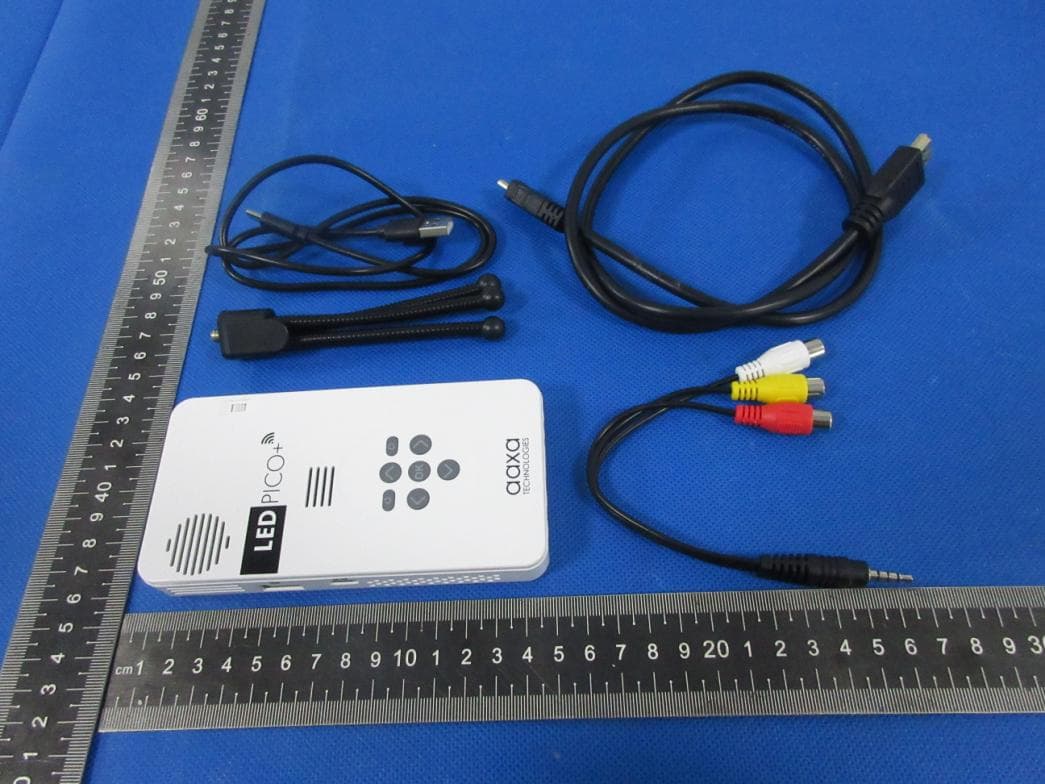
2ANH2-LEDPICOPLUS
Mar 28, 2023Pico Projector LED PICO + with WiFi
Equipment Class
DTS - Digital Transmission System