2ANJ7-USSTDTC3Way Smart Dimmer Switch
Dongguan MaiJia Intelligent Technology Co., Ltd.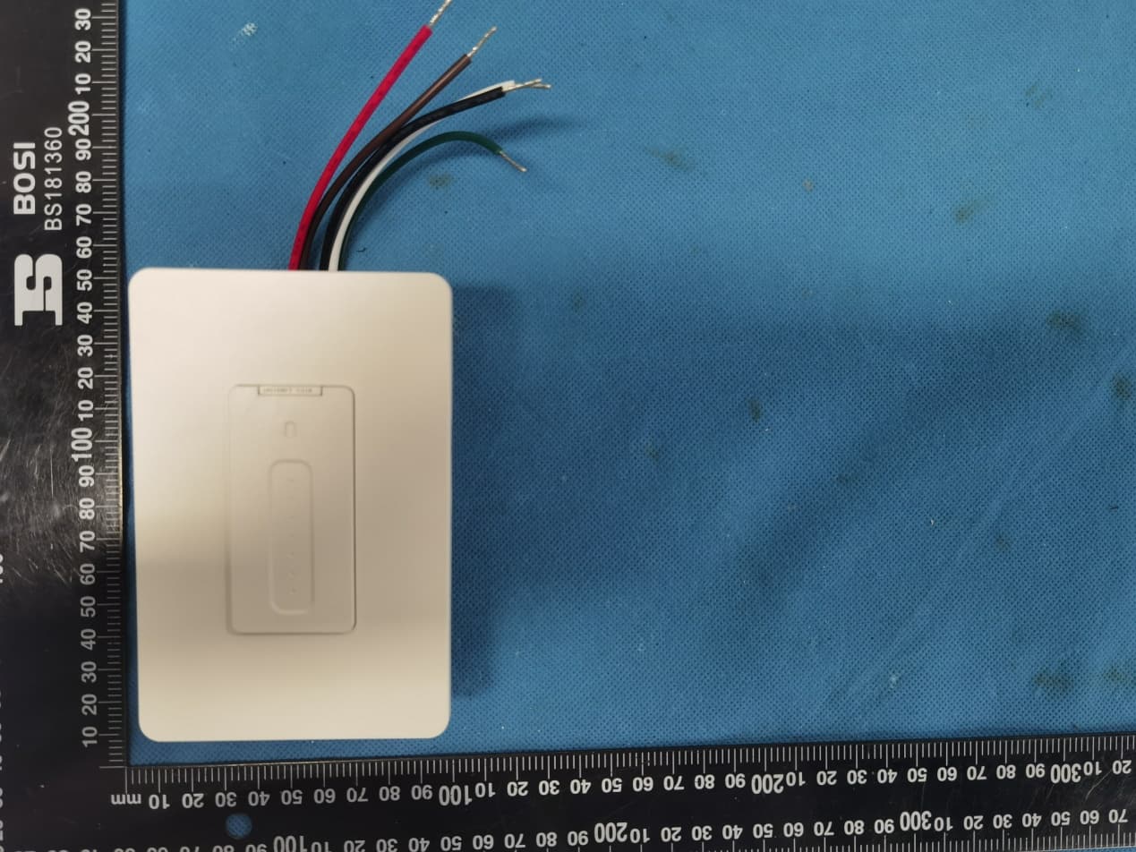
Click to zoom
Application Details
- Equipment Class
- DTS - Digital Transmission System
- Date of Grant
- May 08, 2021
- Application Purpose
- Original Equipment
- Date of Application
- May 08, 2021
- Equipment Note
- 3Way Smart Dimmer Switch
- Frequency Range
- 2412.00000000 - 2462.00000000
- Country
- China
Documents & Files
Document Text
Text extracted from the exhibit documents filed with the FCC. Open a document above to read the original.
Users Manual
1 User Manual 3Way Smart Dimmer Switch Contents Part 1: General................................................................................. 2 1.1. Specification ........................................................ 2 1.2. Main Features ..................................................... 2 Part 2: Installation and Wire Connection.......................................... 3 Part 3: Connect the WiFi Dimmer Switch to Wi-Fi ............................ 5 Part 3: Connect the Dimmer Switch to Alexa.................................. 15 Part 4: Connect the Dimmer Switch to Google Home ..................... 18 2 Part 1: General 1.1. Specification Item Description Product Name 3Way Smart Dimmer Switch Model US-STD-TC01 Color White Voltage 100V-240VAC Frequency 50-60Hz Wattage 150W (LED) 1.2. Main Features Works with Alexa & Google Assistant for voice control ONLY compatible with 2.4G Wi-Fi, DO NOT use it under 5GHz FREE iOS and Android App is available to control it anywhere Set schedule and timing to automatically turn on/off Manually turn on/off the switch by the Main Button Dimmer : Dimmable LED, CFL, halogen & incandescent Bulbs Restart Button Power Button Dimmer Indicator Dim Pad Wi-Fi Button Wi-Fi Indicator 3 Part 2: Installation and Wire Connection Notice: 1. As the switch needs power for itself, three lines must be connected (Live Line, Load Line and Neutral Line); 2. Please use the wire nuts to make the copper conductors fully concealed; 3. If you really cannot find out a Neutral Line in your Power line Socket, STOP installing the switch and consult with a professional electrician or contact our service team. 4 Step 1: Turn off power at the circuit breaker that controls the light switch. Use voltage tester to confirm no voltage is present. Step 2: Remove existing faceplate and light switch, then identify Live/Load, Neutral and Ground lines. Step 3: Connect the Smart Switch wiring with the provided wire connectors as follows: Black wire on switch (Live Line) Live Line White wire on switch (Neutral Line) Neutral line Green wire on switch (Ground Line) Ground line If use it as a Single Pole: Red wire on switch (Load Line) Load line to light bulbs Capped the Brown wire If use it for 3-way: Red & Brown wire on switch Travelers to slave switch Please wrap electrical tape around the wire nuts to make sure the copper conductor is fully concealed. 5 Part 3: Connect the 3Way Smart Dimmer Switch to Wi-Fi Step 1: Download the App Scan the QR code or search “Smart Life” in the App Store or Google Play 6 Step 2: Register a New Account Password must contain 6-20 letters and numbers Register with phone number or email address 7 Step 3: Turn on the power at the circuit breaker. Press the Wi-Fi Button and then the Wi-Fi Indicator light flashes quickly in Red. Flash Quickly in Red: Paring Mode (EZ mode) Constant Green Dimmer Indicator & Wi-Fi Indicator: Power ON, Wi-Fi Connected Constant Red Wi-Fi Indicator: Lost Wi-Fi Connection Dimmer Indicator OFF: Power OFF Step 4: Tap + to Add a device in your App (Smartphone should connect to 2.4GHz Wi-Fi). Step 5: Select “Dimmer Switch” 8 Step 6: Select 2.4 GHz Wi-Fi network and enter your password. (Your phone should have connected to the same Wi-Fi first) Step 7: Select Confirm and tap Next. 9 Step 8: It will be added in around 20 seconds. -----If it fails, try to reconnect and contact the seller for help. After the device is added, Input a proper name and click “Done”. Simple Names will be easier to be identified by Echo or Google Home. 10 Step 9: The switch is connected and you can control it by this App. If you need voice control, please refer to Part 3 for Alexa, Part 4 for Google Assistant. Congratulations! Now you can turn on/off the smart dimmer switch via App on your smartphone. If the above pairing method (EZ mode) fails several times, Please try AP mode as follows: 11 Step 10: Set the switch to AP mode 1. Press the Wi-Fi button once and you will see the indicator blinks quickly. 2. Then press and hold the Wi-Fi button for 5-8s until the indicator blinks slowly. Step 11: After “Step 6: Select 2.4 GHz Wi-Fi network and enter your password,” Tap “EZ Mode” on the top right and select “AP Mode”. 12 Step 12: Select Confirm and tap Next. Step 13: Connect your phone to the device’s hotspot like "Smart Life_xxxx". 13 Step 13: After selecting hotspot like "Smart Life_xxxx" in Wi-Fi setting page, go back to the App and it will connect automatically. Step 14: It will be added in around 20 seconds. After the device is added, Input a proper name and click “Done”. 14 FQA: 1. Cannot download the right App. A: Please come back to step 1 and download by scanning the QR code. Please use a smartphone rather than tablet. 2. Cannot discover the smart switch by App. A: Make sure that your Wi-Fi router is 2.4GHz; DHPC is enabled in the Wi-Fi router; the phone connects to the same Wi-Fi; the Wi-Fi indicator flashes quickly. 3. No light comes out from the Main button/indicator A: Please check the wire connection and press the restart button if necessary, then the Wi-Fi Indicator will blink quickly. 15 Part 3: Connect the Dimmer Switch to Alexa Part 2 must be completed before doing this part 3 Step 1: Log in your Alexa account on a smartphone or a computer, then tap Home Skills Step 2: Search “Smart Life” and select the right one according the blue logo (same with App) 16 Step 3: Enable the skill Step 4: Login the account you registered on the App in Part 2, then click “Link Now” The account and password should be the same as you registered in the Smart Life App. DO NOT input your Alexa account or use another account. 17 Step 5: The Account is linked successfully, and then tap Authorize to Complete. Congratulations! Alexa Devices (Echo) can control the Switch now. To add or delete switches, please delete or add them in the Smart Life App (see Part 2), and then the Alexa will synchronize automatically. If you cannot see the name of sw…
Text truncated - open the document above for the full version.
Cover Letter(s)
Dongguan MaiJia lntelligent Technology Co., Ltd. Agent Authorization Company: Dongguan MaiJia lntelligent Technology Co., Ltd. Address: Room 202, 2F, Building A, No.2 of ManYuan, Hengtang, Tangxia, Dongguan, China Product Name: 3Way Smart Dimmer Switch Model Number(s): US-STD-TC01, US-STD-TC02, US-STD-TC03, US-STD-TC04, US-STD- TC05, US-STD-TC06 Product Description: 3Way Smart Dimmer Switch We authorize MiCOM Labs Inc., 575 Boulder Court, Pleasanton, California 94566, USA, to act on our behalf on all matters concerning the certification of above named equipment. We declare that MiCOM Labs Inc. is allowed to forward all information related to the approval and certification of equipment to the regulatory agencies as required and to discuss any issues concerning the approval application. Any and all acts carried out by MiCOM Labs on our behalf shall have the same effect as acts of our own. Signature: Date: May. 07, 2021 Name: Lynn Liu Title: manager Company: Dongguan MaiJia lntelligent Technology Co., Ltd.
Cover Letter(s)
Dongguan MaiJia lntelligent Technology Co., Ltd. Office of Engineering Technology Federal Communications Commission 7435 Oakland Mills Road Columbia, MD 21046 USA Date: May. 07, 2021 Subject; Request for Confidentiality FCC ID: 2ANJ7-USSTDTC To Whom It May Concern, Pursuant to the provisions of the Commission’s rules Title 47 Sections §0.457 and §0.459, we are requesting the Commission to withhold the following attachment(s) as confidential documents from public disclosure indefinitely. These documents contain detailed system and equipment descriptions and are considered as proprietary information in operation of the equipment. The public disclosure of these documents might be harmful to our company and would give competitors an unfair advantage in the market. Schematic Diagram Block Diagram Parts List Operational Description Tune-up Procedure It is our understanding that all measurement test reports, FCC ID label format and correspondence during the certification review process cannot be granted as confidential documents and this information will be available for public review once the grant of equipment authorization is issued. Sincerely, Signature: Name: Lynn Liu Title: manager
Cover Letter(s)
Model Difference Declaration To Whom It May Concern, We, Dongguan MaiJia lntelligent Technology Co., Ltd. ( 3Way Smart Dimmer Switch) Trademark:N/A; Model Number: US-STD-TC01, US-STD-TC02, US-STD-TC03, US- STD-TC04, US-STD-TC05, US-STD-TC06; All model’s the function, software and electric circuit are the same, only with a product shapes and model named different. Test sample model: US-STD-TC01 for commercial purpose. Please contact me if you have any question. Name: Lynn Liu Date: May. 07, 2021 Title: manager Signature of applicant:
External Photos
Annex A External Photos Report No.: US‐STD‐TC01 Page 1 of 4 Report No.: US‐STD‐TC01 Page 2 of 4 Report No.: US‐STD‐TC01 Page 3 of 4 Report No.: US‐STD‐TC01 Page 4 of 4
ID Label/Location Info
FCC ID LABEL: Ca. 5mm x 10mm Include in manual: This device complies with part 15 of the FCC Rules. Operation is subject to the following two conditions: (1) This device may not cause harmful interference, and (2) this device must accept any interference received, including interference that may cause undesired operation. Label Location FCC ID: 2ANJ7-USSTDTC
Internal Photos
Annex B Internal Photos Report No.: US‐STD‐TC01 Page 1 of 5 Report No.: US‐STD‐TC01 Page 2 of 5 Report No.: US‐STD‐TC01 Page 3 of 5 Report No.: US‐STD‐TC01 Page 4 of 5 Report No.: US‐STD‐TC01 Page 5 of 5
RF Exposure Info
MPE ESTIMATION FCC ID: 2ANJ7-USSTDTC 1,Limit for General Population/ Uncontrolled Exposures Frequency Power density (mW/ cm 2 ) Averaging time(minutes) 300MHz----1.5GHz F/1500 30 1.5GHz---100GHz 1.0 30 Note: F= Frequency in MHz 2, Estimation Result Mode Frequency (MHz) Max PK Output power(dBm) Tune Up Power(dBm) Max Tune Up power(mW) Antenna Gain(dBi) Antenna Gain (linear) MPE ( mW/cm²) 2.4GWIFI 2462 19.39 20±1(21) 125.89 2.5 1.7783 0.04454 Note: Note: The estimation distance is 20cm Note: PK Output power= conducted power. Conducted power see the test report HK2012241208-E, antenna gain=2.5dBi when the minimum test separation distance is >20 cm, a distance of 20 cm is applied to determine RF Exposure test exclusion. The test exclusion threshold is 0.04454 mW/cm² which is< 1.0mW/cm², RF Exposure testing is not required. -------The End-------
Test Report
Report No.: HK2012241208-E FCC TEST REPORT Test report On Behalf of Dongguan MaiJia lntelligent Technology Co., Ltd. For 3Way Smart Dimmer Switch Model No.: US-STD-TC01, US-STD-TC02, US-STD-TC03, US-STD-TC04, US-STD-TC05, US-STD-TC06 FCC ID: 2ANJ7-USSTDTC Prepared for : Dongguan MaiJia lntelligent Technology Co., Ltd. Room 202, 2F, Building A, No.2 of ManYuan, Hengtang, Tangxia, Dongguan, China Prepared By : Shenzhen HUAK Testing Technology Co., Ltd. 1F, B2 Building, JunfengZhongchengZhizao Innovation Park, Fuhai Street, Bao'an District, Shenzhen City, China Date of Test: Dec. 24, 2020 ~ Apr. 21, 2021 Date of Report: Apr. 21, 2021 Report Number: HK2012241208-E Report No.: HK2012241208-E Page 2 of 60 TEST RESULT CERTIFICATION Applicant’s name .................. : Dongguan MaiJia lntelligent Technology Co., Ltd. Address .................................. : Room 202, 2F, Building A, No.2 of ManY uan, Hengtang, T angxia, Dongguan, China Manufacture's Name ............ : Dongguan MaiJia lntelligent Technology Co., Ltd. Address .................................. : Room 202, 2F, Building A, No.2 of ManY uan, Hengtang, T angxia, Dongguan, China Product description Trade Mark: N/A Product name ............................ : 3Way Smart Dimmer Switch Model and/or type reference : US-STD-TC01, US-STD-TC02, US-STD-TC03, US-STD-TC04, US-STD-TC05, US-STD-TC06 Standards .............................. : FCC Rules and Regulations Part 15 Subpart C Section 15.247 ANSI C63.10: 2013 This publication may be reproduced in whole or in part for non-commercial purposes as long as the Shenzhen HUAK Testing Technology Co., Ltd. is acknowledged as copyright owner and source of the material. Shenzhen HUAK Testing Technology Co., Ltd. takes no responsibility for and will not assume liability for damages resulting from the reader's interpretation of the reproduced material due to its placement and context. Date of Test ............................................ : Date (s) of performance of tests ............. : Dec. 24, 2020 ~ Apr. 21, 2021 Date of Issue .......................................... : Apr. 21, 2021 Test Result .............................................. : Pass T esting Engineer : (Gary Qian) Technical Manager : (Eden Hu) Authorized Signatory : (Jason Zhou) Report No.: HK2012241208-E Page 3 of 60 TABLE OF CONTENTS 1. Test Result Summary ............................................................................... 5 1.1. TEST PROCEDURES AND RESULTS ............................................................................................... 5 1.2. TEST FACILITY .................................................................................................................................. 5 1.3. MEASUREMENT UNCERTAINTY ............................................................................................................... 6 2. EUT Description ........................................................................................ 7 2.1. GENERAL DESCRIPTION OF EUT ................................................................................................... 7 2.2. CARRIER FREQUENCY OF CHANNELS ..................................................................................................... 8 2.3. OPERATION OF EUT DURING TESTING .................................................................................................... 8 2.4. DESCRIPTION OF TEST SETUP ....................................................................................................... 9 3. Genera Information ................................................................................. 10 3.1. TEST ENVIRONMENT AND MODE ............................................................................................................ 10 3.2. DESCRIPTION OF SUPPORT UNITS ........................................................................................................ 11 4. Test Results and Measurement Data .................................................... 12 4.1. CONDUCTED EMISSION ........................................................................................................................ 12 4.2. TEST RESULT ...................................................................................................................................... 14 4.3. MAXIMUM CONDUCTED OUTPUT POWER .............................................................................................. 16 4.4. EMISSION BANDWIDTH ......................................................................................................................... 18 4.5. POWER SPECTRAL DENSITY ................................................................................................................ 23 4.6. CONDUCTED BAND EDGE AND SPURIOUS EMISSION MEASUREMENT ..................................................... 28 4.7. RADIATED SPURIOUS EMISSION MEASUREMENT ................................................................................... 36 4.8. PHOTOGRAPH OF TEST ................................................................................................................. 58 4.9. PHOTOS OF THE EUT ..................................................................................................................... 60 Report No.: HK2012241208-E Page 4 of 60 ** Modifited History ** Revison Description Issued Data Remark Revsion 1.0 Initial Test Report Release 2021-04-21 Jason Zhou Report No.: HK2012241208-E Page 5 of 60 1. Test Result Summary 1.1. TEST PROCEDURES AND RESULTS Requirement CFR 47 Section Result Antenna requirement §15.203/§15.247 (c) PASS AC Power Line Conducted Emission §15.207 PASS Conducted Peak Output Power §15.247 (b)(3) PASS 6dB Emission Bandwidth §15.247 (a)(2) PASS Power Spectral Density §15.247 (e) PASS Band Edge §15.247(d) PASS Spurious Emission §15.205/§15.209 PASS Note: 1. PASS: Test item meets the requirement. 2. Fail: Test item does not meet the requirement. 3. N/A: Test case does not apply to the …
Text truncated - open the document above for the full version.
Test Setup Photos
Test Model:US-STD-TC01 Radiated Emission
Contact Information
Applicant
Lynn Liu(manager)
Technical Contact
Test Firm
Shenzhen HUAK Testing Technology Co., Ltd.Jason Zhou
[email protected]+86-755-23029901
Technical Specifications
| # | Rule Parts | Frequency Range | Power Output |
|---|---|---|---|
| 1 | 15C | 2.41 GHz - 2.46 GHz | 86.90 mW |
Other Applications from Dongguan MaiJia Intelligent Technology Co., Ltd.
2ANJ7-USSDTC
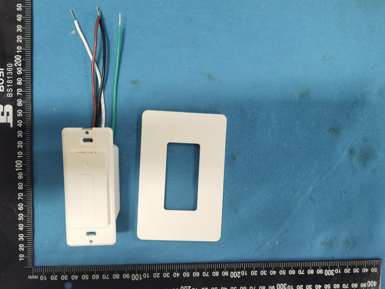
May 08, 2021Smart Dimmer Switch
Equipment Class
DTS - Digital Transmission System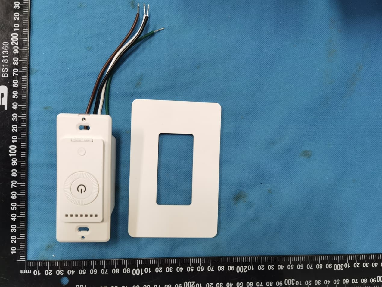
2ANJ7-USSDKN
May 08, 2021Smart Dimmer Switch
Equipment Class
DTS - Digital Transmission System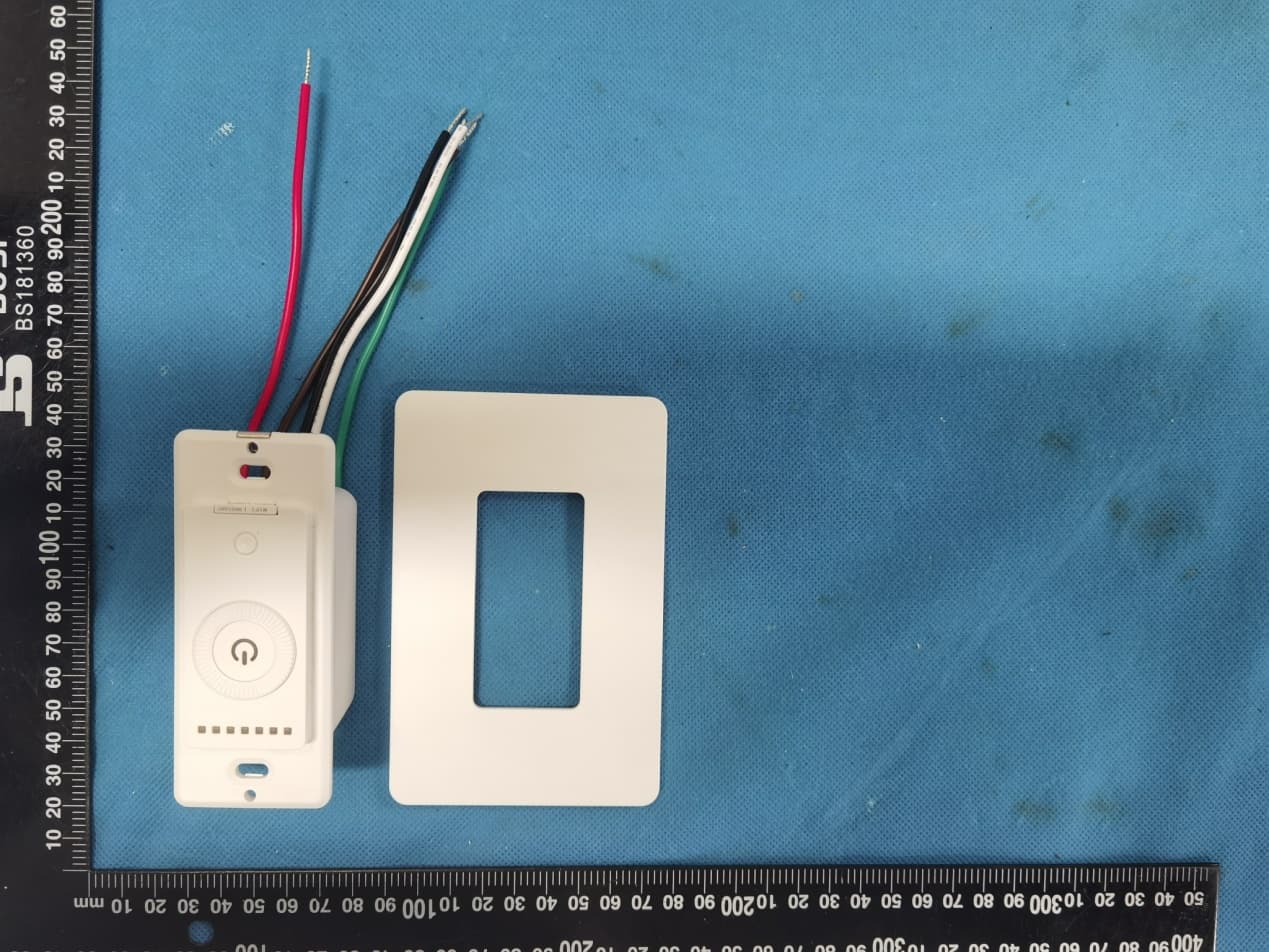
2ANJ7-USSTDKN
May 08, 20213Way Smart Dimmer Switch
Equipment Class
DTS - Digital Transmission System