2ANLH-G1MShortwave transceiver
Chongqing Xiegu Technology Co.,Ltd.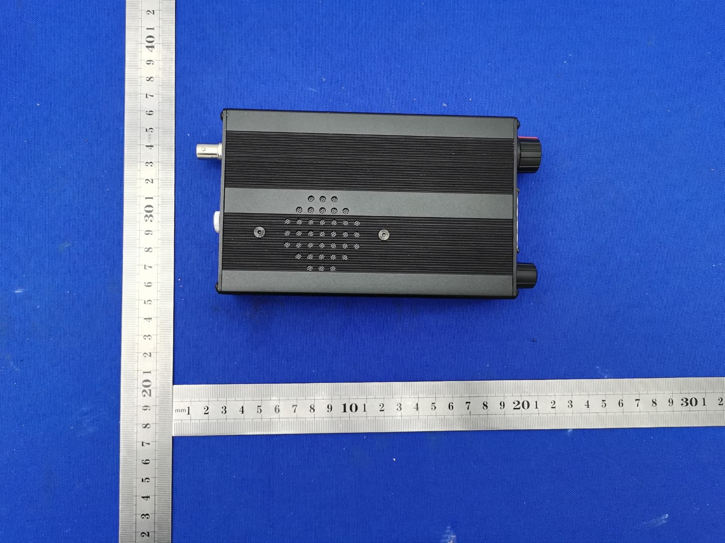
Click to zoom
Application Details
- Equipment Class
- CSR - Scanning Receiver
- Date of Grant
- Apr 19, 2021
- Application Purpose
- Original Equipment
- Date of Application
- Apr 19, 2021
- Equipment Note
- Shortwave transceiver
- Frequency Range
- 0.50000000 - 30.00000000
- Country
- China
Documents & Files
Document Text
Text extracted from the exhibit documents filed with the FCC. Open a document above to read the original.
Users Manual
XIEGU G1M HF Four Band Portable SDR Transceiver Operation Manual V2.0- beta ver G-CORE The new generation G1M (SDR version) is a 5W portable QRP model with SDR structure. Its core is based on 16bit-CODEC sampling and has excellent performance. The newly added AM broadcast reception capability allows you to listen to news broadcasts from around the world; the 800Hz narrowband CW digital filter makes transmission easier and clearer. As an entry-level SDR portable, G1M (SDR version) will provide you with as many new technology experiences as possible. Basic Features: High performance SDR core circuit design New spectrum display function Added AM broadcast receiving mode Added CW Trainer function (supports full insertion) Adaptive speech noise reduction HF continuous reception Support for amateur data communication Support computer online control In order to better experience the Rig, please read this manual carefully before use to fully understand the operation of G1M. 1 面板按键 1 Power switch / volume ○ Rotate the switch to turn the device on or off; ○ After turning the power on, turn the switch knob to increase or decrease the volume of the device. 2 MIC interface External mic interface 3 Multi-function button Menu functions for the screen; 4 LOCK Lock button ○ Light press this button to switch the current menu page; ○ Hold press the button for 2s to lock the button operation. 5 Display screen OLED Display screen 6 Frequency knob ○ Rotate this knob to change the current frequency value; ○ Light press this knob to turn the current function menu. 1 2 3 4 5 6 2 7 Antenna interface BNC model,impedance 50Ω。 8 ACC interface Output band voltage signal and PTT signal. See below. 9 COMM interface PC Communication interface / firmware upgrade interface 10 KEY interface This interface is a 3.5mm stereo jack (3-pin) for connecting manual or automatic telegraph keys. 11 SPK External speaker interface This interface is a 3.5mm stereo jack (3 cord) for connecting external passive speakers. The interface definition is as follows. 12 DC IN external DC power interface This interface is a 5.5*2.5mm DC power socket. 13 Grounding screw nut Ground connection for equipment. 13 12 11 10 9 8 7 3 1、 MIC Note: The MIC pin has a bias voltage and cannot be shorted. 2、 COMM 3、 SPK 4、ACC 5、Telegraph key lead connection method: TXD RXD GND 音频信号 音频信号 GND MIC PTT GND 波段电压 PTT GND 4 The G1M can use a 13.8V external DC power supply. The DC power supply has a current load capacity of at least 3A. The supplied power cord can be used to connect radio and DC power. When connecting the DC power supply, please carefully connect according to the following figure to avoid the polarity of the power supply being reversed. The white core wire is connected to the positive pole of the power supply, and the metal shielded wire is connected to the negative pole of the power supply. 白色线 金属屏蔽线 POWER SUPPLY VOLT ADJ + - ON OFF 5 When the G1M uses an external power supply, in order to prevent external interference from entering the radio through the power line, and radio frequency interference in the radio radiates outward through the power line, an EMC magnetic ring can be placed on the power line. Install the magnetic ring as close as possible to the side of the power plug. When using an external power supply, carefully check the polarity of the power cord to prevent the polarity from being reversed. The limited warranty of this radio does not include damage caused by an external power connection error, or damage caused by abnormal power supply voltage.。 6 The G1M uses the multi-function menu mode for various functions to be used or turned off. All functions are distributed in different menu pages, and each menu has 5 function options. The operation is as follows: Light press the main knob to switch the four-page menu in turn. The five multi-function buttons at the bottom of the screen correspond to the displayed function menu. multi-function buttons main knob 7 Light press the "lock" button to switch the menu page. Hold press the "lock" button to lock the button operation Menu page Button mode Features 1 MD B- B+ TS A/B Light press Mode switching Band subtraction Band increase Step bit selection VFO switching Hold press Preamplifier switch Channel storage Clear channel Step back 1 bit Frequency/channel mode switching 2 KS KM IMB QSK CSN Light press Automatic key rate setting Auto key mode setting Iambic A/B select QSK switch Boot call setting Hold press / CW Sidetone rate setting Code ratio setting QSK time setting / 3 SCL DIS SPL BP / Light press Spectrum SCALE setting Display mode selection Different frequency setting System tone switch / Hold press / / / / / 8 The G1M uses an OLED display screen that displays all status information for the convenience of the user. The visual effect in outdoor sunlight is also very good. NOTE:收发状态:Transmission status;工作模式:Operating mode: 工作频率显示区:Working frequency display area;工作状态显示区:Work status display area; 频谱 /菜单区:Spectrum / menu area 9 Connection to a computer The G1M can be connected to a computer and controlled with the associated software. Connection cable method: 1. Install the driver for the data cable on the PC side. 2. Plug the data cable into the COMM port and connect the G1M to the computer. 3. Run the corresponding computer software. When using software such as HRD, G1M must be in VFO mode , cannot be in channel mode, otherwise it will not be able to connect. 10 Computer control instruction G1M uses the standard CIV instruction set. You can use the standard instructions of this instruction set to remotely control the transceiver. You can also configure the control instructions of other software to control the G1M. Band voltage data G1M's ACC port provides band data for four bands. The band data can control the peripheral device to automatically switch the band or share the band information with other devices. Band Voltage Band Voltage Band Voltage Band Voltage 3.5MHz 460mV 7MHz 920mV 14M…
Text truncated - open the document above for the full version.
Attestation Statements
< Chongqing Xiegu Technology Co.,Ltd. > 13 April 2021 Federal Communications Commission Authorization and Evaluation Division, 7435 Oakland Mills Road Columbia, MD 21046 USA Product Name: Shortwave transceiver Model Number: G1M Trade Mark: FCC Identifier: 2ANLH-G1M Gentlemen: This device must be used with the scanning receiver and cannot be used with other equipment. This device cannot produce any signal. This device complies with FCC Rules, 2.815 The Shortwave transceiver equipment meets the requirements of the FCC Rules, 15.121(a). Compliance is achieved through the following methods: The device in this equipment is incapable of tuning, or readily being altered, by the User to operate within the frequency bands allocated to the Domestic Public Cellular Telecommunications Servic e in Part 22. Blocking of the cellular frequencies is implemented in the firmware of the unit’s main control central processing unit (CPU). Coverage of 824 - 849 MHz and 869 - 894 MHz is completely blocked, since it is done in the microprocessor, and cannot be re-enabled by any user-accessible procedure, including diode, resistor, or jumper changes, nor by connection of any external device such as a personal computer, nor by installation of any “special” enabling semiconductor device. The device shall not be capable of amplification in the frequency band 26-28 MHz. The device is designed so that the tuning, control and filtering circuitry is inaccessible. S incerely, Si gnature: Chongqing Xiegu Technology Co. , Ltd. Name: Mu Lianzheng Title:Manager
Cover Letter(s)
C5266091_X8_Ed.1 Letter of Authorization Chongqing Xiegu Technology Co.,Ltd. Company: Chongqing Xiegu Technology Co.,Ltd. Address: 7-6, Incubator Building, Shuitu High-tech Park, Beibei District, Chongqing, China. Product Name: Shortwave transceiver Model Number: G1M FCC Identifier: 2ANLH-G1M We authorize LGAI Technological Center S.A., Ronda de la Font del Carme, s/n, 08193 Bellaterra, Spain, to act on our behalf on all matters concerning the above named equipment. Any individual within LGAI Technological Center S.A. is authorized to act on our behalf and take action on the application. We declare that authorize LGAI Technological Center S.A., Ronda de la Font del Carme, s/n, 08193 Bellaterra, Spain, is allowed to forward all information related to the approval project to the Federal Communication Commission and to discuss any issues concerning the approval application. Any and all acts carried out by LGAI Technological Center S.A. on our behalf shall have the same effect as acts of our own. Name: Mu Lianzheng Date: 2021.03.25 Title: Manager Signature of applicant: 1/1
Cover Letter(s)
C5266091_X10_Ed.2 Chongqing Xiegu Technology Co.,Ltd. Office of Engineering Technology Federal Communications Commission 7435 Oakland Mills Road Columbia, MD 21046 Date: 2021.03.25 Subject: Request for Confidentiality FCC ID: 2ANLH-G1M To Whom It May Concern, Pursuant to the provisions of Sections 0.457 and 0.459 of Commission's rules (47CFR0.457, 0.459), we are requesting the Commission to withhold the following attachment(s) as confidential document from public disclosure. Exhibits Long-Term Confidentiality Short-Term Confidentiality NOTE 2 ID Label/Location No No Attestation Statement No No External Photos No ☐ Block Diagram ☒ ☐ Schematics ☒ ☐ Test Report No No Test Setup Photos No ☐ User’s Manual ☐ NOTE 1 ☐ Internal Photos ☐ NOTE 1 ☐ Parts List / Tune Up ☐ ☐ RF Exposure Info No No Operational Description ☒ ☐ Cover Letter(s) No No SDR Software / Security Info ☐ No NOTE 1: Long-Term Confidentiality may be permitted under special conditions (See II. LONG-TERM CONFIDENTIALITY, Section 3 of KDB 726920, use last in force) NOTE 2: Short-Term Confidentiality can be requested for a maximum of 180 days from the date of the grant. Above mentioned document contains detailed system and equipment description are considered as proprietary information in operation of the equipment. The public disclosure of above documents might be harmful to our company and would give competitor an unfair advantage in the market. In case of short-term Confidentiality, the applicant requests the exhibits selected above are withheld from public view for a period of ______ days from the date of the Grant of Equipment Authorization and prior to marketing. It is our understanding that all measurement test reports, FCC ID label format and correspondent during certification review process cannot be granted as confidential documents and those information will be available for public review once the grant of equipment authorization is issued. 1/1 C5266091_X10_Ed.2 Sincerely, Signature: Name: Mu Lianzheng Title: Manager 1/1
External Photos
External Photos FCC ID: 2ANLH-G1M
ID Label/Location Info
Model: G1M FCC ID: 2ANLH-G1M Label Location
Internal Photos
Internal Photos FCC ID: 2ANLH-G1M
Test Report
FCC 47 CFR PART 15 Subpart B TEST REPORT Equipment Shortwave transceiver Trademark FCC ID 2ANLH-G1M Model No. G1M Report No. CTB210317015RFX Applicant Chongqing Xiegu Technology Co. , Ltd. 7-6 Incubator Building, No.256, Fangzheng Avenue, Shuitu High-tech park, Beibei district, Chongqing, China Manufacturer Chongqing Xiegu Technology Co. , Ltd. 7-6 Incubator Building, No.256, Fangzheng Avenue, Shuitu High-tech park, Beibei district, Chongqing, China Prepared by Shenzhen CTB Testing Technology Co., Ltd. Floor 1&2, Building A, No. 26 of Xinhe Road, Xinqiao Street, Baoan District, Shenzhen China Tel: 086-4008-707-283 Fax: 086-0755-23208027 Date of Receipt Mar. 09, 2021 Date of Test(s) Mar. 10, 2021 ~ Mar. 16, 2021 Date of Issue Mar. 17, 2021 Test Standard(s) CFR47, FCC Part 15 Subpart B, ANSI C63.4: 2014 In the configuration tested, the EUT complied with the standards specified above. Producer : , Date : Mar. 17, 2021 Bin Mei / Engineer Signatory : , Date : Mar. 17, 2021 Rita Xiao / Director Note: The results shown in this test report refer only to the sample(s) tested unless otherwise stated. This test report shall not be reproduced except in full, without prior written approval of CTB. This document may be altered or revised by CTB, personnel only, and shall be noted in the revision of the document. Page 2 / 19 Report No.: CTB210317015RFX Revision History Edition No. Date of Revision Revision Summary Report Number 0 Mar. 17, 2021 Original Report CTB210317015RFX Page 3 / 19 Report No.: CTB210317015RFX Table of Contents 1. GENERAL INFORMATION ................................................................................................................................... 4 1.1. Description of EUT ..................................................................................................................................... 4 2. TEST SUMMARY ................................................................................................................................................... 5 3. FACILITIES .............................................................................................................................................................. 6 3.1. Test Facility .................................................................................................................................................. 6 3.2. Test Instruments .......................................................................................................................................... 6 4. Measurement uncertainty ...................................................................................................................................... 7 4.1. Operating condition of EUT....................................................................................................................... 7 4.2. Test conditions............................................................................................................................................. 7 4.3. DESCRIPTION OF TEST SETUP ........................................................................................................................ 7 5. Conducted Emission .............................................................................................................................................. 8 5.1. Limit ............................................................................................................................................................... 8 5.2. Test setup ..................................................................................................................................................... 8 5.3. EMI Test Receiver Setup ........................................................................................................................... 8 5.4. Test procedure............................................................................................................................................. 9 5.5. Test results ................................................................................................................................................... 9 6. Radiated emissions .............................................................................................................................................. 10 6.1. Limit ............................................................................................................................................................. 10 6.2. Test setup ................................................................................................................................................... 10 6.3. Test procedure........................................................................................................................................... 11 6.4. Corrected Amplitude & Margin Calculation .......................................................................................... 11 6.5. Test results ................................................................................................................................................. 11 7. Photographs of test setup ................................................................................................................................... 16 8. Photographs of EUT ............................................................................................................................................. 17 Page 4 / 19 Report No.: CTB210317015RFX 1. GENERAL INFORMATION 1.1. Description of EUT Equipment Shortwave transceiver Trade Mark Model Name G1M Serial No. N/A Model Difference N/A Receive frequency 0.5-30MHz I/O Port N/A EUT Power Rating DC 12V Configuration Table-top Floor-standing Cable Supplied USB Note: 1. Other Accessory Device List and Details Description Manufacturer Model Note USB N/A N/A N/A External I/O Cable Cable Description Shielded Type Ferrite Core Length(m) Note - Shielded Non-shielded Yes No 2. The above EUT …
Text truncated - open the document above for the full version.
Test Setup Photos
Radiated Emission Below 1G Above 1G
Contact Information
Applicant
Mu Lianzheng
Technical Contact
Non-Technical Contact
Shenzhen CTB Testing Technology Co., Ltd.Rita Xiao
[email protected](86) 13662574496
Test Firm
Shenzhen CTB Testing Technology Co., Ltd.Rita Xiao
[email protected]86-13538218145
Technical Specifications
| # | Rule Parts | Frequency Range | Power Output |
|---|---|---|---|
| 1 | 15B | 0.5 MHz - 30 MHz | - |