2ANOG-A98MWireless Smart Audio Module (BT, 2.4GHz and 5GHz WIFI)
Linkplay Technology Inc.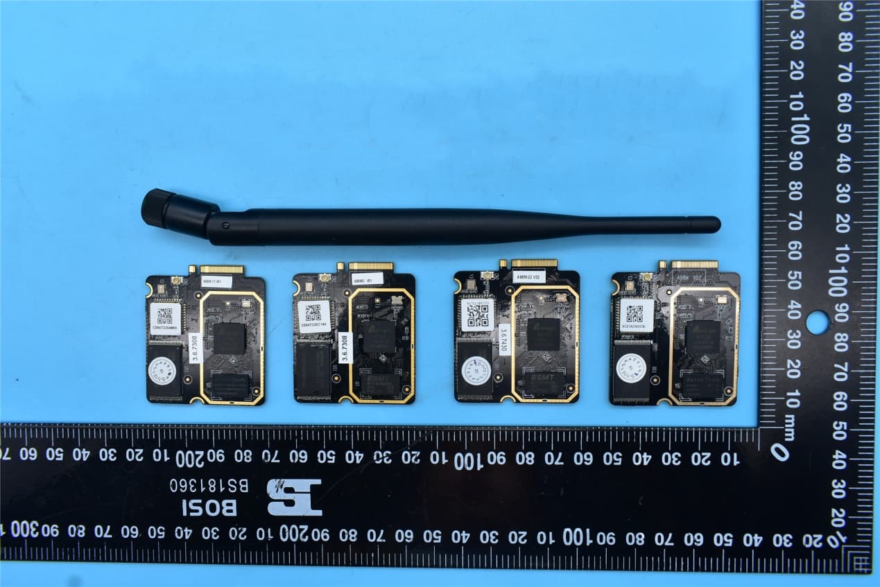
Click to zoom
Application Details
- Equipment Class
- DSS - Part 15 Spread Spectrum Transmitter
- Date of Grant
- Dec 23, 2020
- Application Purpose
- Original Equipment
- Date of Application
- Dec 23, 2020
- Equipment Note
- Wireless Smart Audio Module (BT, 2.4GHz and 5GHz WIFI)
- Frequency Range
- 2402.00000000 - 2480.00000000
- Company
- Linkplay Technology Inc.
- Country
- China
Documents & Files
Document Text
Text extracted from the exhibit documents filed with the FCC. Open a document above to read the original.
Cover Letter(s)
Declaration To whom it may concern: We have declared below featured for FCC equipment authorization, Device FCC ID: 2ANOG-A98M Don't operate on Channels 12 and 13. US 2.4G channel 12-13 and Country code selection are disabled through proprietary software and are not user changeable Should you have any questions, please feel free to contact me. Signature : Date:2020/11/30 Contact name:cunxue wang Title: HW Manager Company name: Linkplay Technology Inc.
Cover Letter(s)
Linkplay Technology Inc. UNII Declaration Letter We have declared below featured for FCC equipment authorization, device FCC ID:2ANOG-A98M (1) DFS Device -- Master,Client with Radar detection capability , Client without radar detection capability,N/A (2) Active / Passive Scanning , adhoc mode access point capability Frequency Band (MHz) Active Scanning (the device can transmit a probe (beacon)) passive scanning (where the device is can listen only with no probes) Ad Hoc Mode capability Access point capability 2412 –2462 MHzYes,NoYes,NoYes,NoYes,No 2422 –2452 MHzYes,NoYes,NoYes,NoYes,No 5745 –5825 MHzYes,NoYes,NoYes,NoYes,No 5755 –5795 MHzYes,NoYes,NoYes,NoYes,No 5180 –5240 MHzYes,NoYes,NoYes,NoYes,No 5190 –5230 MHzYes,NoYes,NoYes,NoYes,No 5260 –5320 MHzYes,NoYes,NoYes,NoYes,No 5270 –5310 MHzYes,NoYes,NoYes,NoYes,No 5500 –5700 MHzYes,NoYes,NoYes,NoYes,No 5510 – 5670 MHz Yes,NoYes,NoYes,NoYes,No (3) Country code selection ability -Yes ,No If no, pls explain how was implemented : Country is selected as US by default and user can not change the country code. (4) Meet 15.202 requirement - Yes ,No , pls check below : A master device is defined as a device operating in a mode in which it has the capability to transmit without receiving an enabling signal. In this mode it is able to select a channel and initiate a network by sending enabling signals to other devices A client device is defined as a device operating in a mode in which the transmissions of the device are under control of the master. A device in client mode is not able to initiate a network. (5) For client devices that have software configuration control to operate in different modes (active scanning in some and passive scanning in others) in different bands (devices with multiple equipment classes or those that operate on non-DFS frequencies) or modular devices which configure the modes of operations through software, the application must provide software and operations description on how the software and / or hardware is implemented to ensure that proper operations modes can not be modified by end user or an installer. Apply ,No Apply, (If apply , pls help to provide explanation on how it was implement (By hardware or software , and how software was controlled) The device configuration can not be modified by user as program is not exposed to user by any means. Hardware does not allow USB connection for user which is must to change the configuration. If you have any questions, please feel free to contact me at the address shown below. Yours sincerely, Signatory: Printed Name : cunxue wang Position : HW Manager
Cover Letter(s)
Linkplay Technology Inc. version01 Modular Approval Request Letter Date:2020-12-24 FCC ID:2ANOG-A98M Type of Equipment: Wireless Smart Audio Module The following requirements according to FCC Part 15.212 are met: i RF shielding The radio portion hasn't its own shielding (see external photos), and the A98M module is suitable for artificial intelligent voice control system such as smart speaker and smart home. ii Buffered modulation/data inputs It has been integrated in the chipset AP6256. iii Power supply regulation It is integrated in circuits of U1/U2/U3/U4. iv Antenna requirements section 15.203, 15.204 b and 15.204 c The module only provides one U.FL Gen1 connector. Spurious emission requirements are met (Refer to the attached test report) v Stand alone test configuration Please refer to test setup configuration photos and as the schematics show,TheRFpathfrom A98m series module to EVB via U14 (AP6256), C108 (filter capacitor), CN2 (IPEX Connector), 20cm RF cable, CN13 (IPEX Connector) and CN12(SMA Connector) in turn. This setup does not affect RF test results. The U14, C108, and CN2 devices are designed on A98M module, CN13 and CN12 devices are designed on EVB. Both CN12 and CN13 are standard RF connector (As shown below). EVB is only used to assist A98M authentication (It provides 5V DC power supply for A98M module). Its interfaces include Micro USB, USB Type-A, 3.5mm phone jack, key array, MIC array and LED array etc, so the EVB does not affect the RF test results. Linkplay Technology Inc. version01 vi Labelling The module has its own label. The instruction of labelling rules for the host device has been stated in the user manual. vii Compliance on specific rule or operating requirements The required FCC rules has been fulfilled and all instructions of maintaining compliance are clearly stated in the user manual. viii RF Exposure RF exposure requirements are fulfilled for mobile configuration. The installation of the module is restricted to mobile host devices what is clearly stated in the installation instruction of the user manual. For portable applications, OEM integrators need SAR evaluation and an own FCC ID. Name: Cunxue Wang Title: HW Manager Company: Linkplay Technology Inc.
Cover Letter(s)
Page 1 of 4 Ref: KDB 594280 D02 U-NII / RSS-247article 6.4(4). SOFTWARE SECURITY INFORMATION FCC ID: 2ANOG-A98M Pursuant to: FCC Part 15E 15.407(I) and KDB 594280 D02 UNII Device Security v01r03 / IC RSS-247article 6.4(4). The information within this section is to show compliance against the SW Security Requirements laid out within KDB 594280 D02 U-NII Device Security v01r03. The information below describes how to maintain the overall security measures and systems so that only: 1. Authenticated software is loaded and operating on the device. 2. The device is not easily modified to operate with RF parameters outside of the authorization. SOFTWARE SECURITY DESCRIPTION RequirementAnswer General Description 1. Describe how any software/firmware updates for elements than can affect the device’s RF parameters will be obtained, downloaded, validated and installed. For software that is accessed through manufacturer’s website or device’s management system, describe the different levels of security as appropriate. The factory firmware is produced by Grantee and it is delivered to the factory via a secured channel. The factory loads the firmware to the device on the production line with specialized tools not available to consumers.. 2. Describe the RF parameters that are modified by any software/firmware without any hardware changes. Are these parameters in some way limited such that any other software/firmware changes will not allow the device to exceed the authorized RF characteristics? The RF parameters have been confirmed in accordance with FCC regulations, and burned into the device. The unauthorized person can not modify via changing the firmware or other ways. 3. Describe in detail the authentication protocols that are in place to ensure that the source of the RF-related software/firmware is valid. Describe in detail how the RF-related software is protected against modification. No authentication is applied for firmware download, but FSG power on protection is applied to protect the factory RF calibration data from corruption or tempering. 4. Describe in detail any encryption methods used to support the use of legitimate RF- related software/firmware. Yes, see answers to #1 and #3. 5.For a device that can be configured as a master and client (with active or passive scanning), explain how the device ensures compliance for each mode? In particular if the device acts as master in some band of operation and client in another; how is compliance ensured in each band of operation? Please refer to test report,this device is the slave, which is compliant with FCC regulation demands. Page 2 of 4 Ref: KDB 594280 D02 U-NII / RSS-247article 6.4(4). RequirementAnswer Third Party Access Control 1. Explain if any third parties have the capability to operate a U.S./Canada - sold device on any other regulatory domain, frequencies, or in any manner that may allow the device to operate in violation of the device’s authorization if activated in the U.S./Canada. Only Grantee can release or make changes to the software/firmware 2. Describe, if the device permits third-party software or firmware installation, what mechanisms are provided by the manufacturer to permit integration of such functions while ensuring that the RF parameters of the device cannot be operated outside its authorization for operation in the U.S./Canada. In the description include what controls and/or agreements are in place with providers of third-party functionality to ensure the devices’ underlying RF parameters are unchanged and how the manufacturer verifies the functionality. No, refer to the answers #1, 2, and 3 under General Description 3. For Certified Transmitter modular devices, describe how the module grantee ensures that host manufacturers fully comply with these software security requirements for U-NII devices. If the module is controlled through driver software loaded in the host, describe how the drivers are controlled and managed such that the modular transmitter RF parameters are not modified outside the grant of authorization. RF parameters are written in a special location by factory tool. The RF partition can’t changed by software update. Manufactures do NOT have source code of the factory tool, nor can they change any RF parameters. 4.Auto-discontinue mechanism description The automatic disconnection mechanism was set up before the factory. The product automatically stops transmission when the operation fails or when no information is transmitted. This section is required for devices which have a “User Interface” (UI) to configure the device in a manner that may impact the operational parameter. The operation description must address if the device supports any of the country code configurations or peer-peer mode communications discussed in KDB 594280 D01. SOFTWARE CONFIGURATION DESCRIPTION RequirementAnswer R CONFIGURATION GUIDE 1. Describe the user configurations permitted through the UI. If different levels of access are permitted for professional installers, system integrators orend-users, describe the differences. This product is a module and does not support UI operations a) What parameters are viewable and configurable by different parties? None that affects compliance b) What parameters are accessible or None that affects compliance Page 3 of 4 Ref: KDB 594280 D02 U-NII / RSS-247article 6.4(4). modifiable by the professional installer or system integrators? (1) Are the parameters in some way limited, so that the installers will not enter parameters that exceed those authorized? Not applicable as these types of settings are not accessible to any operating party. (2) What controls exist that the user cannot operate the device outside its authorization in the U.S./Canada? The device does not allow third-party access to software / firmware parameters or configurations including operation outside the scope of U.S authorization. c) What parameters are accessible or modifiable by the end-user? None that affects compliance (…
Text truncated - open the document above for the full version.
External Photos
FCC ID:2ANOG-A98M External Photos 1. EUT top view 2. EUT bottom view
ID Label/Location Info
Label: Location:
Internal Photos
FCC ID:2ANOG-A98M Internal Photos 1. EUT uncover view 2. Antenna view Bluetooth/Wi-Fi Antenna
RF Exposure Info
NOTE: This document is issued by MORLAB, the test report shall not be reproduced except in full without prior written permission of the company. The test results apply only to the particular sample(s) tested and to the specific tests carried out which is available on request for validation and information confirmed at our website. MORLAB SHENZHEN MORLAB COMMUNICATIONS TECHNOLOGY Co., Ltd. FL1-3, Building A, FeiYang Science Park, No.8 LongChang Road, Block67, BaoAn District, ShenZhen , GuangDong Province, P. R. China Tel: 86-755-36698555 Fax: 86-755-36698525 Http://www.morlab.cn E-mail: [email protected] Page 1 of 11 REPORT No.:SZ20110203S01 RF EXPOSURE EVALUATION REPORT APPLICANT : Linkplay Technology Inc. PRODUCT NAME : Wireless Smart Audio Module MODEL NAME :A98M, A98M-12, A98M-22, A98MG BRAND NAME : Linkplay FCC ID : 2ANOG-A98M STANDARD(S) : 47CFR 2.1091 KDB 447498 RECEIPT DATE : 2020-11-17 TEST DATE :2020-11-21 to 2020-12-06 ISSUE DATE :2020-12-08 Edited by: Zeng Xiaoying (Rapporteur) Approved by: Peng Huarui (Supervisor) MORLAB SHENZHEN MORLAB COMMUNICATIONS TECHNOLOGY Co., Ltd. FL1-3, Building A, FeiYang Science Park, No.8 LongChang Road, Block67, BaoAn District, ShenZhen , GuangDong Province, P. R. China Tel: 86-755-36698555 Fax: 86-755-36698525 Http://www.morlab.cn E-mail: [email protected] REPORT No.:SZ20110203S01 Page 2of 11 DIRECTORY 1. Technical Information ∙∙∙∙∙∙∙∙∙∙∙∙∙∙∙∙∙∙∙∙∙∙∙∙∙∙∙∙∙∙∙∙∙∙∙∙∙∙∙∙∙∙∙∙∙∙∙∙∙∙∙∙∙∙∙∙∙∙∙∙∙∙∙∙∙∙∙∙∙∙∙∙∙∙∙∙∙∙∙∙∙∙∙∙∙∙∙∙∙∙∙∙∙∙∙∙∙∙∙∙∙∙∙∙ 3 1.1 Applicant and Manufacturer Information ∙∙∙∙∙∙∙∙∙∙∙∙∙∙∙∙∙∙∙∙∙∙∙∙∙∙∙∙∙∙∙∙∙∙∙∙∙∙∙∙∙∙∙∙∙∙∙∙∙∙∙∙∙∙∙∙∙∙∙∙∙∙∙∙∙∙∙∙∙ 3 1.2 Equipment under Test (EUT) Description ∙∙∙∙∙∙∙∙∙∙∙∙∙∙∙∙∙∙∙∙∙∙∙∙∙∙∙∙∙∙∙∙∙∙∙∙∙∙∙∙∙∙∙∙∙∙∙∙∙∙∙∙∙∙∙∙∙∙∙∙∙∙∙∙∙∙∙∙ 3 1.3 Applied Reference Documents ∙∙∙∙∙∙∙∙∙∙∙∙∙∙∙∙∙∙∙∙∙∙∙∙∙∙∙∙∙∙∙∙∙∙∙∙∙∙∙∙∙∙∙∙∙∙∙∙∙∙∙∙∙∙∙∙∙∙∙∙∙∙∙∙∙∙∙∙∙∙∙∙∙∙∙∙∙∙∙∙∙∙∙∙∙ 4 2. Device Category and RF Exposure Limit ∙∙∙∙∙∙∙∙∙∙∙∙∙∙∙∙∙∙∙∙∙∙∙∙∙∙∙∙∙∙∙∙∙∙∙∙∙∙∙∙∙∙∙∙∙∙∙∙∙∙∙∙∙∙∙∙∙∙∙∙∙∙∙∙∙∙∙∙∙∙∙ 5 3. RF Output Power ∙∙∙∙∙∙∙∙∙∙∙∙∙∙∙∙∙∙∙∙∙∙∙∙∙∙∙∙∙∙∙∙∙∙∙∙∙∙∙∙∙∙∙∙∙∙∙∙∙∙∙∙∙∙∙∙∙∙∙∙∙∙∙∙∙∙∙∙∙∙∙∙∙∙∙∙∙∙∙∙∙∙∙∙∙∙∙∙∙∙∙∙∙∙∙∙∙∙∙∙∙∙∙∙∙∙∙∙∙∙∙∙ 6 4. RF Exposure Assessment ∙∙∙∙∙∙∙∙∙∙∙∙∙∙∙∙∙∙∙∙∙∙∙∙∙∙∙∙∙∙∙∙∙∙∙∙∙∙∙∙∙∙∙∙∙∙∙∙∙∙∙∙∙∙∙∙∙∙∙∙∙∙∙∙∙∙∙∙∙∙∙∙∙∙∙∙∙∙∙∙∙∙∙∙∙∙∙∙∙∙∙∙∙∙ 10 Annex A Testing Laboratory Information ∙∙∙∙∙∙∙∙∙∙∙∙∙∙∙∙∙∙∙∙∙∙∙∙∙∙∙∙∙∙∙∙∙∙∙∙∙∙∙∙∙∙∙∙∙∙∙∙∙∙∙∙∙∙∙∙∙∙∙∙∙∙∙∙∙∙∙∙∙∙∙∙∙∙∙ 11 Change History Version Date Reason for Change 1.0 2020-12-08 First edition MORLAB SHENZHEN MORLAB COMMUNICATIONS TECHNOLOGY Co., Ltd. FL1-3, Building A, FeiYang Science Park, No.8 LongChang Road, Block67, BaoAn District, ShenZhen , GuangDong Province, P. R. China Tel: 86-755-36698555 Fax: 86-755-36698525 Http://www.morlab.cn E-mail: [email protected] REPORT No.:SZ20110203S01 Page 3of 11 1. Technical Information Note: Provide by applicant. 1.1 Applicant and Manufacturer Information Applicant: Linkplay Technology Inc. Applicant Address: 8F-8036, Qianren Building, No.7, Yingcui Road, Jiangning District, Nanjing, China Manufacturer: Linkplay Technology Inc. Manufacturer Address: 8F-8036, Qianren Building, No.7, Yingcui Road, Jiangning District, Nanjing, China 1.2 Equipment under Test (EUT) Description Product Name: Wireless Smart Audio Module Serial No.: (N/A, marked #1 by test site) Hardware Version: V02 Software Version: Linkplay.3.6.7430 Frequency Bands: Bluetooth 2402MHz-2480MHz WLAN 2.4GHz 2412MHz–2462MHz WLAN 5GHz 5180MHz-5240MHz 5260MHz-5320MHz 5500MHz-5720MHz 5745MHz-5825MHz Modulation Mode: Bluetooth GFSK(1Mbps), π/4-DQPSK(EDR 2Mbps), 8-DPSK(EDR 3Mbps) WLAN 2.4GHz DSSS, OFDM WLAN 5GHz OFDM Antenna Type: External Rod Antenna Antenna Gain: Bluetooth 3.13dBi WLAN 2.4GHz 3.13dBi WLAN 5GHz 3.73dBi MORLAB SHENZHEN MORLAB COMMUNICATIONS TECHNOLOGY Co., Ltd. FL1-3, Building A, FeiYang Science Park, No.8 LongChang Road, Block67, BaoAn District, ShenZhen , GuangDong Province, P. R. China Tel: 86-755-36698555 Fax: 86-755-36698525 Http://www.morlab.cn E-mail: [email protected] REPORT No.:SZ20110203S01 Page 4of 11 Note 1: According to the certificate holder, they declared that the models A98M, A98M-12, A98M-22 and A98MG have different ROM and RAM density, different brands or different vendors. The differences do not affect BT/Wi-Fi RF performance. The detailed information of differences is listed below. The main measuring model is A98M, only the results for A98M were recorded in this report. A98M: 128MB RAM, 128MB FLASH A98M-12: 128MB RAM, 256MB FLASH A98M-22: 256MB RAM, 256MB FLASH A98MG: 512MB RAM, 512MB FLASH 1.3 Applied Reference Documents Leading reference documents for testing: No. Identity Document Title Method determination /Remark 1 47 CFR§2.1091 Radio Frequency Radiation Exposure Assessment: mobile devices No deviation 2 KDB 447498 D01v06 General RF Exposure Guidance No deviation Note 1: Additions to, deviation, or exclusions from the method shall be judged in the "method determination" column of add, deviate or exclude from the specific method shall be explained in the "Remark" of the above table. Note 2: When the test result is a critical value, we will use the measurement uncertainty give the judgment result based on the 95% risk level. MORLAB SHENZHEN MORLAB COMMUNICATIONS TECHNOLOGY Co., Ltd. FL1-3, Building A, FeiYang Science Park, No.8 LongChang Road, Block67, BaoAn District, ShenZhen , GuangDong Province, P. R. China Tel: 86-755-36698555 Fax: 86-755-36698525 Http://www.morlab.cn E-mail: [email protected] REPORT No.:SZ20110203S01 Page 5of 11 2. Device Category and RF Exposure Limit Per user manual, Based on 47CFR 2.1091, this device belongs to mobile device category with General Population/Uncontrolled exposure. Mobile Devices: 47CFR 2.1091(b) For purposes of this section, a mobile device is defined as a transmitting device designed to be used in other than fixed locations and to generally be used in such a way that a separation distance of at least 20 centimeters is normally maintained between the transmitter's radiating structure(s) and the body of the user or nearby persons. In this…
Text truncated - open the document above for the full version.
Test Setup Photos
FCC ID:2ANOG-A98M Test Setup Photos 1. Conducted emission main’s port front view 2. Conducted emission main’s port side view 3. Radiated emission (9KHz-30MHz) 4. Radiated emission (30MHz-1GHz) 5. Radiated emission (above 1GHz) 6. RF measurement setup (Bluetooth BR+EDR)
Contact Information
Applicant
cunxue wang(HW Manager)
Test Firm
Shenzhen Morlab Communications Technology Co. Ltd.Mr. Su Feng
[email protected]+86 755 36698566
Technical Specifications
| # | Rule Parts | Frequency Range | Power Output |
|---|---|---|---|
| 1 | 15C | 2.40 GHz - 2.48 GHz | 6.00 mW |
Other Applications from Linkplay Technology Inc.
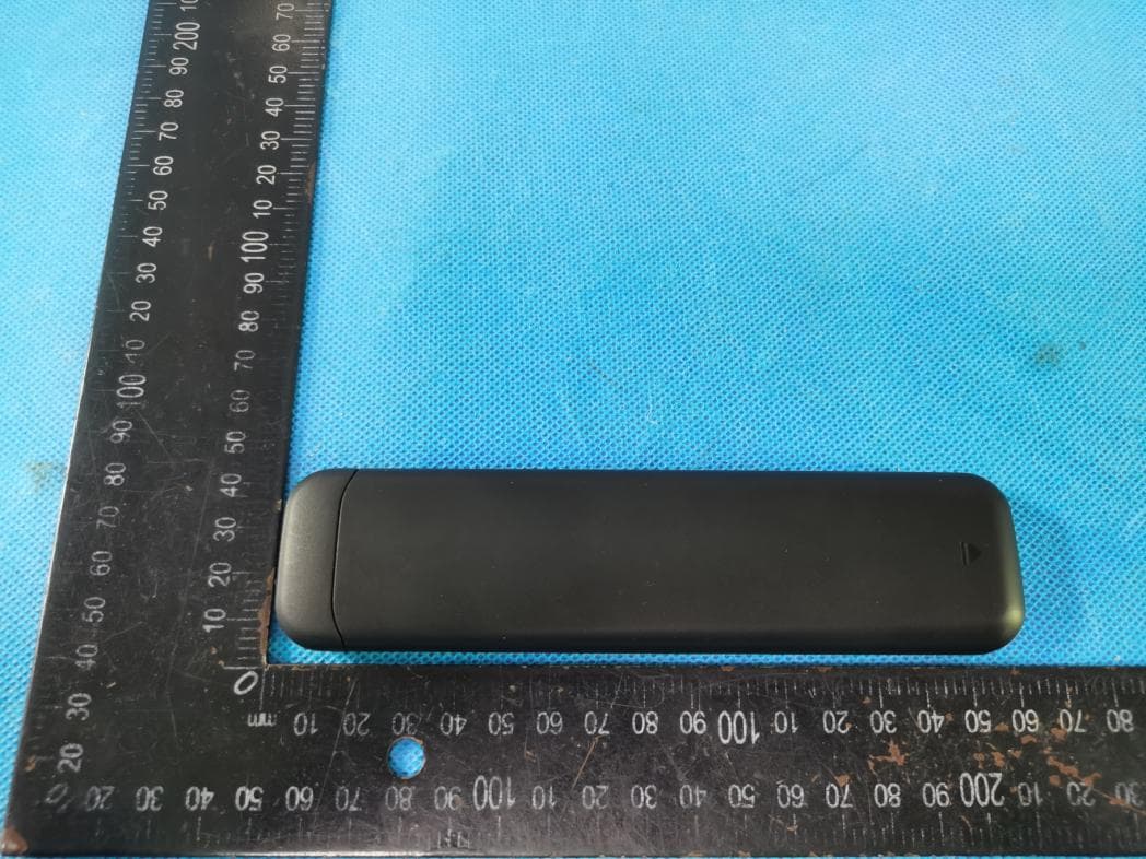
2ANOG-WVR001
Feb 20, 2023WiiM Voice Remote
Equipment Class
DTS - Digital Transmission System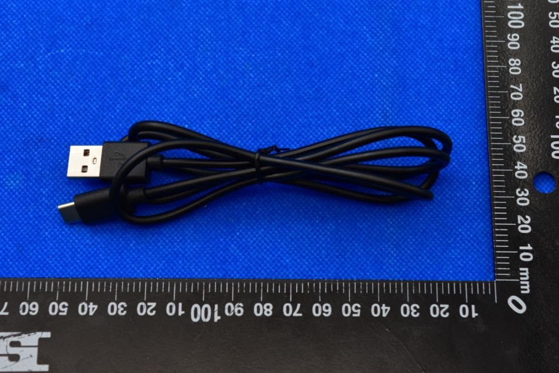
2ANOG-ASR002
Nov 20, 2022WiiM Pro Hi-Res Audio Streamer with WiFi and Bluetooth
Equipment Class
DTS - Digital Transmission System