2AO3F-EA-XRN-9400Radar Sensor
Alphawave Golf (Pty) Ltd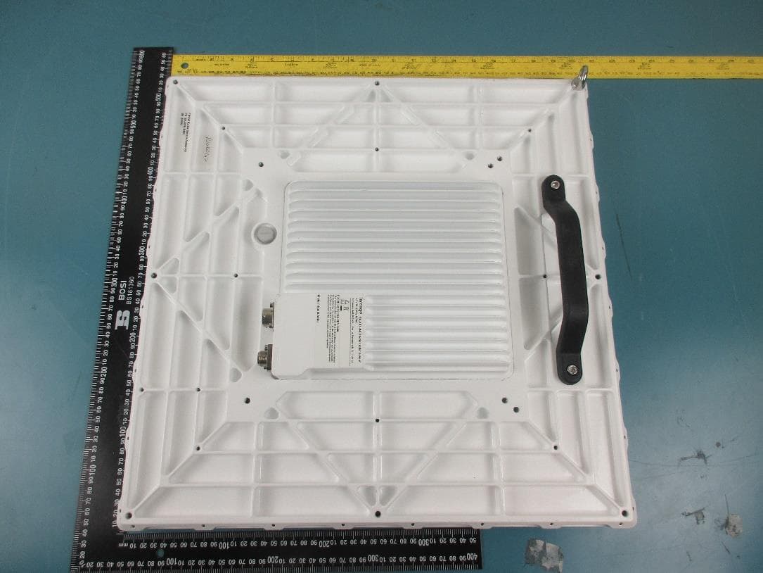
Click to zoom
Application Details
- Equipment Class
- TNB - Licensed Non-Broadcast Station Transmitter
- Date of Grant
- Jul 04, 2022
- Application Purpose
- Original Equipment
- Date of Application
- Jul 04, 2022
- Equipment Note
- Radar Sensor
- Frequency Range
- 10000.00000000 - 10500.00000000
- Company
- Alphawave Golf (Pty) Ltd
- Country
- South Africa
Documents & Files
Document Text
Text extracted from the exhibit documents filed with the FCC. Open a document above to read the original.
Users Manual
Document Number EA-XRN-9400-OMM Revision 1 Classification Commercial in Confidence Date 2022-06-20 Radar Sensor EA-XRN-9400 series User Manual and Installation Instructions EA-XRN-9400 User Manual 2022-06-20 Page 2 of 16 CONTENTS 1. SYMBOLS ...................................................... 5 2. GENERAL INFORMATION ............................ 6 3. SAFETY INFORMATION ............................... 9 4. INSTALLATION INSTRUCTIONS ............... 10 4.1 Installation guidelines 10 4.2 Mechanical Mounting 11 4.3 Connections and Grounding 13 5. MAINTENANCE AND SERVICE.................. 13 5.1 Inspection 13 5.2 Cleaning 14 6. DISPOSAL ................................................... 14 EA-XRN-9400 User Manual 2022-06-20 Page 3 of 16 The information in this guide may change without notice. The manufacturer assumes no responsibility for any errors that may appear in this guide. Federal Communications Commission (FCC) FCC ID: 2AO3F-EA-XRN-9400 This device complies with Part 15 of the FCC rules. Operation is subject to the following conditions: (1) This device may not cause harmful interference, and (2) this device must accept any interference received, including interference that may cause undesired operation. This equipment has been tested and found to comply with the limits for a Class A digital device, pursuant to part 15 of the FCC Rules. These limits are designed to provide reasonable protection against harmful interference when the equipment is operated in a commercial environment. This equipment generates, uses, and can radiate radio frequency energy and, if not installed and used in accordance with the instruction manual, may cause harmful interference to radio communications. Operation of this equipment in a residential area is likely to cause harmful interference in which case the user will be required to correct the interference at his own expense. EA-XRN-9400 User Manual 2022-06-20 Page 4 of 16 This equipment complies with FCC radiation exposure limits set forth for an uncontrolled environment. End users must follow the specific operating instructions for satisfying RF exposure compliance. This transmitter must be at least 72 cm from the user and must not be co-located or operating in conjunction with any other antenna or transmitter. EA-XRN-9400 User Manual 2022-06-20 Page 5 of 16 1. SYMBOLS Read the manual before installing or working near sensor. Only for EU countries: Do not dispose of electric equipment in household waste. Warning for hazardous situations with regards to life and property. EA-XRN-9400 User Manual 2022-06-20 Page 6 of 16 2. GENERAL INFORMATION The radar sensor EA-XRN-9400 is a golf ball tracking radar. Each sensor is installed as part of a system designed to cover a specific volume at a golf facility, and provide trajectory data of all ball flights within its field of view. The user of the sensor is assumed to be the owner/operator of the facility. The sensors are installed in fixed locations that are accessible only by qualified personnel, and not by the general public. Control and monitoring of the sensors are provided via manufacturer supplied software from a central server that is set up and configured by trained and qualified personnel. Once configured, the operator only has access to basic commands to activate or deactivate sensors but cannot modify or alter the configuration or mode of operation of the sensors. EA-XRN-9400 User Manual 2022-06-20 Page 7 of 16 The figure below shows the connections to the sensor. The M6 mounting holes are located at the back of the sensor. Figure 1: Drawing of the radar sensor indicating the power and fibre connections. EA-XRN-9400 User Manual 2022-06-20 Page 8 of 16 Table 1: Product Specification Specification Value Device Type FMCW 3D Tracking Radar Frequency Range 10.0 to 10.5 GHz Channel Bandwidth 100 MHz linear sweep Antenna Type Patch antenna array Antenna Gain 10.5 dBi peak Transmit Power 31.65 dBm (42.15 dBm EIRP) Supply voltage 48 V DC ±10% Power Consumption < 40 W Dimensions 500 × 500 × 85 mm Weight 9 kg EA-XRN-9400 User Manual 2022-06-20 Page 9 of 16 3. SAFETY INFORMATION The guidelines in this section needs to be followed to ensure proper and safe operation of the equipment. Changes or modifications to the sensor that are not expressly approved by the manufacturer, and implemented by suitably qualified personnel, could void the user’s authorisation to operate the equipment. When installed according to the instructions in this manual, operation of this radio device results in user exposure below the FCC recommended limits. See the appendix for more information. Only trained personnel are allowed to install or replace this equipment. The equipment can only be serviced at the factory by qualified personnel. Do not attempt to open the unit. Device installation may require the installer to work at heights. Take all necessary precautions to ensure safety and provide fall arrest equipment where required. Plan the installation carefully before proceeding. Be aware of hazards such as power lines or other electrical circuits, e.g. lighting fixtures. Do not approach within 72 cm of the sensor when it is operating. EA-XRN-9400 User Manual 2022-06-20 Page 10 of 16 The manufacturer or a trained installation technician shall install the sensor and perform all necessary actions to set it up and verify the correct operation thereof. After installation, the user must not modify the connections or alter the installation, without the approval of the installers. The device does not contain any user-serviceable parts and the user should not attempt to remove the device or disassemble it. 4. INSTALLATION INSTRUCTIONS 4.1 Installation guidelines Prior to installation, please check that the (factory installed) radome is in place on the radar sensor and that all its fasteners are present. The location of each installed sensor location must be known precisely to ensure correct system operation. During installation, the location of ea…
Text truncated - open the document above for the full version.
Attestation Statements
Frequency Justification Letter 2022-04-07 FEDERAL COMMUNICATIONS COMMISSIONS Authorization and Evaluation Division 7435 Oakland Mills Road Columbia, MD 21046 Subject: Frequency Justification Attestation for FCC ID: 2AO3F-EA-XRN-9400 We, Alphawave Golf (Pty) Ltd acknowledge that this device will not be marketed to USA users with the frequency band not allowed by rule part 90, and that it is a violation of FCC rules if this device is operated with unauthorized frequencies in the USA. We, Alphawave Golf (Pty) Ltd hereby declare this equipment meets the requirement of FCC Part 90.203(3) and (g). Programming of this product’s transmit frequencies can be performed only by the manufacturer or by service or maintenance personnel. The operator cannot program transmit frequencies using the equipment’s operation. Sincerely, SJ Marais, Director 18 Techno Avenue, Stellenbosch 7599, South Africa
Cover Letter(s)
QA-FR-172-A FCC Confidential Authorization 2022-04-07 FEDERAL COMMUNICATIONS COMMISSIONS Authorization and Evaluation Division 7435 Oakland Mills Road Columbia, MD 21046 Subject: Confidentiality Request regarding application for certification of FCC ID: 2AO3F-EA-XRN-9400 In accordance with Sections 0.457 and 0.459 of the Commission’s Rules, Alphawave Golf (Pty) Ltd hereby requests long-term confidential treatment of information accompanying this application as outlined below: • Block Diagram • Schematics • Operation Description • Parts List • Tune up procedure • Internal Photos • User’s Manual As well as short-term confidential treatment of information accompanying this application as outlined below: • External Photos • Test Set-up Photos The above materials contain proprietary and confidential information not customarily released to the public. The public disclosure of these materials provides unjustified benefits to its competitors in the market. Sincerely, SJ Marais, Director 18 Techno Avenue, Stellenbosch 7599, South Africa
Cover Letter(s)
Confidential EA-XRN-9400-DOS-01_1 Alphawave Golf (Pty) Ltd 18 Techno Avenue, Techno Park, Stellenbosch, 7600, South Africa PO Box 492, Stellenbosch, 7599, South Africa Tel: (+27) 21 880 1188 Reg no: 2017 / 160832 / 07 VAT no: 4870279272 Declaration of Similarity 2022-05-03 To: FEDERAL COMMUNICATIONS COMMISSIONS Authorization and Evaluation Division 7435 Oakland Mills Road Columbia, MD 21046 Dear Sir or Madam: Alphawave Golf (Pty) Ltd hereby declares that product: Golf Radar Sensor, model: EA-XRN-9401 is electrically identical with the same electromagnetic emissions and electromagnetic compatibility characteristics as model: EA-XRN-9400. The differences between the models are as follows: • The gain of the passive receive antennas of EA-XRN-9400 is around 10.5 dBi. • The gain of the passive receive antennas of EA-XRN-9401 is around 2 dB higher than for those of EA-XRN-9400. Please contact me should there be any need for additional clarification or information. Best Regards, ___________________________________________ S.J. Marais Director
Cover Letter(s)
Mutual Non-Disclosure Agreement between Alphawave Golf Proprietary Limited, a company duly incorporated in accordance with the laws of the Republic of South Africa with its principal place of business at 18 Techno Avenue, Techno Park, Stellenbosch, South Africa, 7600, registration number: 2017/160832/07 (“Alphawave”), (“the Disclosing Party”) and ________________________________________________________________________ , a __________________________________________ , with its principle place of business at _________________________________________________________________________, (“____________________________”) (“the Receiving Party”) 2 WHEREAS: A. The parties intend to engage in discussions in relation to entering into a possible business relationship in terms of which the Disclosing Party will in the course of such discussions disclose certain Confidential Information to the Receiving Party. B. The Parties wish to enter into this agreement to regulate the use and disclosure of the Confidential Information. 1. DEFINITIONS In this agreement, including the preamble, unless the context otherwise requires: 1.1 “Confidential Information Means all confidential information relating to either party which comes into possession or under the control of the Receiving Party in any manner whatsoever, in the course of negotiations, involvement, and discussions with the Disclosing Party and whether such information is oral or written or recorded or stored in electronic or in any other medium, as well as confidential information of relating to either party and its business or products including information constituting trade secrets including, without being limited to methods, processes and procedures, quality control measures and systems formulas and know-how and other information and irrespective of whether such information is marked “confidential” or “proprietary” or otherwise. The Receiving Party acknowledges that even though certain information included within the Confidential Information may be available to the public, it is the combination of the various components of the Confidential Information that renders the information confidential and proprietary. 1.2 “the Disclosing Party” Alphawave Golf Proprietary Limited who is disclosing the Confidential Information to the Receiving Party; 1.3 “the Parties” Means the Disclosing Party and the Receiving Party; 1.4 “the Receiving Party” _____________________________________________ _____________________________________________ _____________________________________________ _____________________________________________ 1.5 words and expressions defined in the Companies Act, 1973, shall bear the same meanings in this agreement. 3 2. UNDERTAKINGS 2.1 The Receiving Party undertakes in favour of the Disclosing Party that it: 2.1.1 shall not disclose, directly or indirectly, to any other party, any of the Confidential Information; 2.1.2 shall not permit or allow the disclosure, directly or indirectly, to any party, any of the Confidential Information; 2.1.3 shall not make any use of, or use by any means, either directly or indirectly, any Confidential Information; 2.1.4 shall not use the Confidential Information for any purpose other than in connection with the assessment and negotiations relating to a possible transaction with; 2.1.5 shall not take or make copies of any Confidential Information or authorise any other persons to do so; 2.1.6 shall take all such steps as are necessary to prevent the Confidential Information falling into the hands of unauthorised third parties; and 2.1.7 without limiting the generality of the foregoing, shall not use or attempt to use the Confidential Information in any manner which may cause injury or loss to the Disclosing Party. 2.2 Notwithstanding the provisions of 2.1, the Parties agree that the Confidential Information may be disclosed by the Receiving Party to its professional advisers, provided that the Receiving Party shall procure that such professional advisers, agree to abide by the terms of this agreement in order to prevent the unauthorised disclosure of the Confidential Information to third parties. 2.3 All documentation furnished to the Receiving Party by the Disclosing Party pursuant to this agreement shall remain the property of the Disclosing Party and the Receiving Party shall return all such documentation to the Disclosing Party forthwith upon request by the Disclosing Party. The Receiving Party shall not duplicate or make copies by any means of any such documentation other than for purposes of this Agreement without the prior written consent of the Disclosing Party. 4 3. DURATION This agreement will, irrespective of the date of signature hereof, be deemed to have commenced on the date upon which any part or element of the Confidential Information was disclosed to the Receiving Party or became known to the Receiving Party and shall continue for a maximum of twenty four (24) months or until the Confidential Information loses its confidential nature by being purchased by the Receiving Party or clearly becoming part of the public domain, otherwise than by a wrongful act by the Receiving Party or any person to whom the Disclosing Party disclosed it. The Receiving Party’s obligations under this Agreement shall survive termination of the Agreement between the parties and shall be binding upon the Receiving Party’s heirs, successors and assigns. The Receiving Party’s obligations with respect to all Confidential Information shall be terminated only pursuant to Section 4. 4. EXCLUSION Any information that: 4.1 was clearly in the public domain prior to its disclosure by the Disclosing Party to the Receiving Party or subsequently clearly became part of the public domain by publication or otherwise than by a wrongful act by the Receiving Party or any person to whom the Disclosing Party disclosed it; or 4.2 was in the Receiving Party’s possession immediately prior to its disclosure by the Disclosing Party to the Receiving…
Text truncated - open the document above for the full version.
External Photos
Alphawave Golf (Pty) Ltd. FCC ID: 2AO3F-EA-XRN-9400 EUT External Photographs 1.1 EUT – Top View 1.2 EUT – Bottom View Alphawave Golf (Pty) Ltd. FCC ID: 2AO3F-EA-XRN-9400 1.3 EUT – Front View 1.4 EUT – Rear View Alphawave Golf (Pty) Ltd. FCC ID: 2AO3F-EA-XRN-9400 1.5 EUT – Right Side View 1.6 EUT – Left Side View
ID Label/Location Info
1 EA-XRN-9400/9401 Label Examples and Locations Date: 2022-04-13 • The labelling is divided in to two labels as shown in Figure 1 below: o Main label: All regulatory codes, symbols, addresses etc. o Additional label: part name, part number and serial number. Figure 1: Label location(s) on EA-XRN-9400 series sensor. • A sample of the main label is shown in Figure 2. • Samples of the additional labels for the EA-XRN-9400 and EA-XRN-9401 sensors are shown in Figure 3 and Figure 4. The number after SN: is the device serial number. 2 Figure 2: Sample main label. Figure 3: Sample additional label: EA-XRN-9400 sensor. Figure 4: Sample additional label: EA-XRN-9401 sensor.
RF Exposure Info
Alphawave Golf (Pty) Ltd. FCC ID: 2AO3F-EA-XRN-9400 Report Number: R2204012-90 Page 12 of 53 FCC Part 90 Test Report 4 FCC §1.1307(b) (1), §2.1091 &§90.223 - RF Exposure 4.1 Applicable Standards According to FCC KDB 447498 D04 Interim General RF Exposure Guidance v01, Section 2.1 RF Exposure Test Exemptions for Single Source, 2.1.1 General RF Exposure Test Exemption Considerations RF exposure test exemptions provide means to obtain certification without the need of showing data (measurements, or analytical/numerical modeling) to demonstrate compliance. Hereafter, in this context, an RF source is referred to as “exempt RF device” in the sense that it is not required to show data demonstrating compliance to RF exposure limits. Test exemptions apply for devices used in general population/uncontrolled exposure environments, according to the SAR-based, or MPE-based exemption thresholds. 8 However, it is always possible, especially when the potential for exposure cannot be easily determined, that an RF exposure evaluation may become required according §§ 1.1307(c) and (d). As detailed in Section 2.1.2, the 1 mW and SAR-based test exemption conditions are in terms of source-based available maximum time-averaged (matched conducted) output power for all operating configurations, adjusted for tune-up tolerance, and at the minimum test separation distance required for the particular RF exposure scenario under consideration. This minimum test separation distance is determined by the smallest distance from the antenna and radiating structures or outer surface of the device, according to the host form factor, exposure conditions and platform requirements, to any part of the body or extremity of a user or bystander. To qualify for SAR test exemption, the test separation distances applied must be fully explained and justified (typically in the SAR measurement, or SAR analysis report, according to KDB Pub. 865664) by showing the actual operating configurations and exposure conditions of the transmitter, and applicable host platform requirements (e.g., KDB Pubs. 648474, 616217, 941225) When no other RF exposure testing or reporting is required, a statement of justification and compliance must be included in the equipment approval, in lieu of the SAR report, to qualify for SAR test exemption. If RF exposure testing requirements for a specific device are covered in a KDB Publication, those requirements must be satisfied before applying any SAR test exemption provisions. For example, this is the case for handheld PTT two-way radios, handsets, laptops, and tablets, etc. 9 Finally, when 10-g extremity SAR applies, SAR test exemption may be considered by applying a factor of 2.5 to the SAR-based exemption thresholds. 2.1.2 1-mW Test Exemption Per §1.1307(b)(3)(i)(A), a single RF source is exempt RF device (from the requirement to show data demonstrating compliance to RF exposure limits, as previously mentioned) if the available maximum time-averaged power is no more than 1 mW, regardless of separation distance. This exemption applies to all operating configurations and exposure conditions, for the frequency range 100 kHz to 100 GHz, regardless of fixed, mobile, or portable device exposure conditions. This is a standalone exemption, and it cannot be applied in conjunction with any other test exemption. 2.1.3 SAR-Based Exemption Alphawave Golf (Pty) Ltd. FCC ID: 2AO3F-EA-XRN-9400 Report Number: R2204012-90 Page 13 of 53 FCC Part 90 Test Report A more comprehensive exemption, considering a variable power threshold that depends on both the separation distance and power, is provided in §1.1307(b)(3)(ii)(B). This exemption is applicable to the frequency range between 300 MHz and 6 GHz, with test separation distances between 0.5 cm and 40 cm, and for all RF sources in fixed, mobile, and portable device exposure conditions. Accordingly, a RF source is considered an RF exempt device if its available maximum time-averaged (matched conducted) power or its effective radiated power (ERP), whichever is greater, are below a specified threshold. This exemption threshold was derived based on general population 1-g SAR requirements and is detailed in Appendix C. 2.1.4 MPE-Based Exemption An alternative to the SAR-based exemption is provided in §1.1307(b)(3)(ii)(C), for a much wider frequency range, from 300 kHz to 100 GHz, applicable for separation distances greater or equal to λ/2π, where λ is the free-space operating wavelength in meters. The MPE-based test exemption condition is in terms of ERP, defined as the 8 Specific test exemption thresholds for operations under occupational/controlled limits are not established. 9 When SAR evaluation is required by the hotspot mode or UMPC mini-tablet procedures, that is, where an antenna is ≤ 2.5 cm from a surface or edge, the test separation distance from the phantom to the antenna or device enclosure, as appropriate, should be applied to determine SAR test exemption for such configurations, according to the criteria in this document. For that case, the test separation distance cannot be determined from the distance of the antenna to the device surface or edge. According to ISED RSS-102 Issue 5 Section 2.5.1 Exemption Limits for Routine Evaluation-SAR Evaluation: SAR evaluation is required if the separation distance between the user and/or bystander and the antenna and/or radiating element of the device is less than or equal to 20 cm, except when the device operates at or below the applicable output power level (adjusted for tune-up tolerance) for the specified separation distance defined in table below, Frequency (MHz) Exemption Limits (mW) At separation distance of ≤5 mm At separation distance of 10 mm At separation distance of 15 mm At separation distance of 20 mm At separation distance of 25 mm ≤300 71 101 132 162 193 450 52 70 88 106 123 835 17 30 42 55 67 1900 7 10 18 34 60 2450 4 7 15 30 52 3500 2 6 16 32 55 5800 1 6 15 27 41 Alphawave Golf (Pty) Ltd. FCC ID: 2AO3F-EA-XRN-9400 …
Text truncated - open the document above for the full version.
Test Report
Note: This test report is prepared for the customer shown above and for the device described herein. It may not be duplicated or used in part without prior written consent from Bay Area Compliance Laboratories Corp. This report must not be used by the customer to claim product certification, approval, or endorsement by A2LA* or any agency of the Federal Government. * This report may contain data that are not covered by the A2LA accreditation and are marked with an asterisk “*” (Rev.3) FCC PART 90 TEST REPORT For Alphawave Golf (Pty) Ltd. 18 Techno Ave, Technopark, Stellenbosch, 7600, South Africa FCC ID: 2AO3F-EA-XRN-9400 R e p o r t T y p e : O r i g i n a l R e p o r t P r o d u c t T y p e: F M C W R a d a r S e n s o r Prepared By: Arturo Reyes Test Engineer Report Number: R2204012-90 Report Date: 2022-06-15 Reviewed By: Christian McCaig RF Lead Engineer Bay Area Compliance Laboratories Corp. 1274 Anvilwood Avenue, Sunnyvale, CA 94089, USA Tel: +1 (408) 732-9162, Fax: +1 (408) 732-9164 Alphawave Golf (Pty) Ltd. FCC ID: 2AO3F-EA-XRN-9400 Report Number: R2204012-90 Page 2 of 53 FCC Part 90 Test Report TABLE OF CONTENTS 1 GENERAL INFORMATION ............................................................................................................................... 5 1.1 PRODUCT DESCRIPTION FOR EQUIPMENT UNDER TEST (EUT) ........................................................................... 5 1.2 MECHANICAL DESCRIPTION .............................................................................................................................. 5 1.3 OBJECTIVE ......................................................................................................................................................... 5 1.4 RELATED SUBMITTAL(S)/GRANT(S) ................................................................................................................... 5 1.5 TEST METHODOLOGY ........................................................................................................................................ 5 1.6 MEASUREMENT UNCERTAINTY .......................................................................................................................... 6 1.7 TEST FACILITY REGISTRATIONS ........................................................................................................................ 6 1.8 TEST FACILITY ACCREDITATIONS ...................................................................................................................... 7 2 SYSTEM TEST CONFIGURATION .................................................................................................................. 9 2.1 JUSTIFICATION ................................................................................................................................................... 9 2.2 EUT EXERCISE SOFTWARE ................................................................................................................................ 9 2.3 EQUIPMENT MODIFICATIONS ............................................................................................................................. 9 2.4 REMOTE SUPPORT EQUIPMENT LIST AND DETAILS ............................................................................................ 9 2.5 LOCAL SUPPORT EQUIPMENT LIST AND DETAILS .............................................................................................. 9 2.6 POWER SUPPLY .................................................................................................................................................. 9 2.7 INTERFACE PORTS AND CABLING .................................................................................................................... 10 3 SUMMARY OF TEST RESULTS ...................................................................................................................... 11 4 FCC §1.1307(B) (1), §2.1091 &§90.223 - RF EXPOSURE ............................................................................... 12 4.1 APPLICABLE STANDARDS ................................................................................................................................ 12 4.2 FCC RF EXPOSURE EXEMPTION EVALUATION PROCEDURES .......................................................................... 14 4.3 RF EXPOSURE EVALUATION EXEMPTION FOR FCC........................................................................................... 17 5 FCC §2.1046, §90.205(S) & §90.103(C) - RF OUTPUT POWER .................................................................... 18 5.1 APPLICABLE STANDARDS ................................................................................................................................ 18 5.2 TEST PROCEDURE ............................................................................................................................................ 18 5.3 TEST SETUP BLOCK DIAGRAM ......................................................................................................................... 18 5.4 TEST EQUIPMENT LIST AND DETAILS .............................................................................................................. 18 5.5 TEST ENVIRONMENTAL CONDITIONS ............................................................................................................... 19 5.6 TEST RESULTS ................................................................................................................................................. 20 6 FCC §2.1049 & §90.209 - OCCUPIED BANDWIDTH .................................................................................... 22 6.1 APPLICABLE STANDARDS ................................................................................................................................ 22 6.2 TEST PROCEDURE ............................................................................................................................................ 22 6.3 TEST SETUP BLO…
Text truncated - open the document above for the full version.
Test Setup Photos
Alphawave Golf (Pty) Ltd. FCC ID: 2AO3F-EA-XRN-9400 Test Setup Photographs 1.1 Radiated Spurious Emissions Test Setup Below 1 GHz – Front View 1.2 Radiated Spurious Emissions Test Setup Below 1 GHz – Rear View Alphawave Golf (Pty) Ltd. FCC ID: 2AO3F-EA-XRN-9400 1.3 Radiated Spurious Emissions Test Setup 1 GHz – 18 GHz – Front View 1.4 Radiated Spurious Emissions Test Setup 1 GHz – 18 GHz – Rear View Alphawave Golf (Pty) Ltd. FCC ID: 2AO3F-EA-XRN-9400 1.5 Radiated Spurious Emissions Test Setup 18 GHz – 26.5 GHz – Front View 1.6 Radiated Spurious Emissions Test Setup 18 GHz – 26.5 GHz – Rear View Alphawave Golf (Pty) Ltd. FCC ID: 2AO3F-EA-XRN-9400 1.7 Radiated Spurious Emissions Test Setup 26.5 GHz – 40 GHz – Front View 1.8 Radiated Spurious Emissions Test Setup 26.5 GHz – 40 GHz – Rear View Alphawave Golf (Pty) Ltd. FCC ID: 2AO3F-EA-XRN-9400 1.9 Radiated Spurious Emissions Test Setup 40-60 GHz
Contact Information
Applicant
SJ Marais
Test Firm
Bay Area Compliance Laboratories Corp.Lisa Tang
Technical Specifications
| # | Rule Parts | Frequency Range | Power Output | Emission | Tolerance |
|---|---|---|---|---|---|
| 1 | 90 | 10.00 GHz - 10.50 GHz | 1.46 W | 100MF3N | 50.0000000000 ppm |