2AO47-B02Smart watch
Shenzhen Kingstar Industrial Co., Ltd.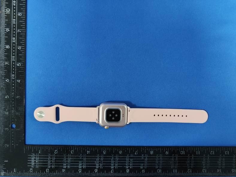
Click to zoom
Application Details
- Equipment Class
- DTS - Digital Transmission System
- Date of Grant
- Aug 04, 2022
- Application Purpose
- Original Equipment
- Date of Application
- Aug 04, 2022
- Equipment Note
- Smart watch
- Frequency Range
- 2402.00000000 - 2480.00000000
- Country
- China
Documents & Files
Document Text
Text extracted from the exhibit documents filed with the FCC. Open a document above to read the original.
External Photos
FCC ID: 2AO47-B02 B02 External Photos of the EUT Photo 1 Photo 2 Photo 3 FCC ID: 2AO47-B02 Photo 4 Photo 5 Photo 6 FCC ID: 2AO47-B02 Photo 7
ID Label/Location Info
Label and Location Size: L: 1.0cm*W: 0.5cm Label and Location FCC ID : 2AO47-B02
Internal Photos
FCC ID: 2AO47-B02 B02 Internal Photos of the EUT Photo 1 Photo 2 Photo 3 BLE Antenna FCC ID: 2AO47-B02 Photo 4 Photo 5 Photo 6 FCC ID: 2AO47-B02 Photo 7 Photo 8
RF Exposure Info
RF Exposure evaluation FCC ID: 2AO47-B02 1.1. Applicable Standard According to §1.1307(b)(1), systems operating under the provisions of this section shall be operated in a manner that ensures that the public is not exposed to radio frequency energy level in excess of the Commission’s guidelines. According to §1.1310 and §2.1093 RF exposure requirement KDB447498 v06: Mobile and Portable Devices RF Exposure Procedures and Equipment Authorization Policies 1.2. Requirement According to KDB447498 D01 General RF Exposure Guidance v06 Section 4.3.1 Standalone SAR test exclusion considerations: “Unless specifically required by the published RF exposure KDB procedures, standalone 1-g head or body and 10-g extremity SAR evaluation for general population exposure conditions, by measurement or numerical simulation, is not required when the corresponding SAR Test Exclusion Threshold condition, listed below, is satisfied. These test exclusion conditions are based on source-based time-averaged maximum conducted output power of the RF channel requiring evaluation, adjusted for tune-up tolerance, and the minimum test separation distance required for the exposure conditions.22 The minimum test separation distance is determined by the smallest distance from the antenna and radiating structures or outer surface of the device, according to the host form factor, exposure conditions and platform requirements, to any part of the body or extremity of a user or bystander (see 5) of section 4.1). To qualify for SAR test exclusion, the test separation distances applied must be fully explained and justified by the operating configurations and exposure conditions of the transmitter and applicable host platform requirements, typically in the SAR measurement or SAR analysis report, according to the required published RF exposure KDB procedures. When no other RF exposure testing or reporting is required, a statement of justification and compliance must be included in the equipment approval, in lieu of the SAR report, to qualify for the SAR test exclusion. When required, the device specific conditions described in the other published RF exposure KDB procedures must be satisfied before applying these SAR test exclusion provisions; for example, handheld PTT two-way radios, handsets, laptops & tablets etc.23 “ [(max. power of channel, including tune-up tolerance, mW)/ (min. test separation distance, mm)] · [√f (GHz)] ≤ 3.0 for 1-g SAR and ≤ 7.5 for 10-g extremity SAR, where: • f (GHz) is the RF channel transmit frequency in GHz • Power and distance are rounded to the nearest mW and mm before calculation • The result is rounded to one decimal place for comparison • 3.0 and 7.5 are referred to as the numeric thresholds in the step 2 below The test exclusions are applicable only when the minimum test separation distance is ≤ 50 mm and for transmission frequencies between 100 MHz and 6 GHz. When the minimum test separation distance is < 5 mm, a distance of 5 mm according to 5) in section 4.1 is applied to determine SAR test exclusion. 1.3. Manufacturing tolerance GFSK (Peak) Channel Channel 0 Channel 19 Channel 39 Target (dBm) 0 0 0 Tolerance ±(dB) 1.0 1.0 1.0 Page 2 of 2 2. E v a l u a t i o n R e s u l t Evaluation Results Band/Mode f (GHz) Antenna Distance (mm) RF output power (including tune-up tolerance) SAR Test Exclusion Threshold SAR Test Exclusion dBm mW BT 2.450 5 1.0 1.2589 0.3941<3.0 Yes 3. C o n c l u s i o n The measurement results comply with the FCC Limit per 47 CFR 2.1093 for the uncontrolled RF Exposure and SAR Exclusion Threshold per KDB 447498 v06 .....................End of Report.........................
Test Report
Shenzhen CTA Testing Technology Co., Ltd. Room 106, Building 1, Yibaolai Industrial Park, Qiaotou Community, Fuhai Street, Bao’an District, Shenzhen, China Shenzhen CTA Testing Technology Co., Ltd. Room 106, Building 1, Yibaolai Industrial Park, Qiaotou Community, Fuhai Street, Bao’an District, Shenzhen, China Tel:+86-755 2322 5875 E-mail:[email protected] Web:http://www.cta-test.cn FCC PART 15 SUBPART C TEST REPORT FCC PART 15.247 Report Reference No. ..................... : FCC ID. ............................................ : CTA22071800101 2AO47-B02 Compiled by ( position+printed name+signature) .. : File administrators Kevin Liu Supervised by ( position+printed name+signature) .. : Project Engineer Kevin Liu Approved by ( position+printed name+signature) .. : RF Manager Eric Wang Date of issue ..................................... : Jul. 29, 2022 Testing Laboratory Name .............. : Shenzhen CTA Testing Technology Co., Ltd. Address ............................................ : Room 106, Building 1, Yibaolai Industrial Park, Qiaotou Community, Fuhai Street, Bao’an District, Shenzhen, China Applicant’s name ............................ : Shenzhen Kingstar Industrial Co., Ltd. Address ............................................ : Room 211, Min Le technology Building Meiban Road, LongHua District, Shenzhen, China Test specification ...........................: Standard ........................................... : FCC Part 15.247 Shenzhen CTA Testing Technology Co., Ltd. All rights reserved. This publication may be reproduced in whole or in part for non-commercial purposes as long as the Shenzhen CTA Testing Technology Co., Ltd. is acknowledged as copyright owner and source of the material. Shenzhen CTA Testing Technology Co., Ltd. takes no responsibility for and will not assume liability for damages resulting from the reader's interpretation of the reproduced material due to its placement and context. Equipment description...................: Smart watch Trade Mark ....................................... : N/A Manufacturer .................................... : Shenzhen Kingstar Industrial Co., Ltd. Model/Type reference....................... : B02 Listed Models .................................. : N/A Modulation ....................................... : GFSK Frequency .......................................... From 2402MHz to 2480MHz Ratings ............................................. : DC 3.7V From Battery and DC 5.0V From external circuit Result................................................ : PASS Report No.: CTA22072501801 Page 2 of 35 Shenzhen CTA Testing Technology Co., Ltd. Room 106, Building 1, Yibaolai Industrial Park, Qiaotou Community, Fuhai Street, Bao’an District, Shenzhen, China Tel:+86-755 2322 5875 E-mail:[email protected] Web:http://www.cta-test.cn T E S T R E P O R T Equipment under Test : Smart watch Model /Type : B02 Listed Models : N/A Applicant : Shenzhen Kingstar Industrial Co., Ltd. Address : Room 211, Min Le technology Building Meiban Road, LongHua District, Shenzhen, China Manufacturer : Shenzhen Kingstar Industrial Co., Ltd. Address : Room 211, Min Le technology Building Meiban Road, LongHua District, Shenzhen, China Test Result: PASS The test report merely corresponds to the test sample. It is not permitted to copy extracts of these test result without the written permission of the test laboratory. Report No.: CTA22072501801 Page 3 of 35 Shenzhen CTA Testing Technology Co., Ltd. Room 106, Building 1, Yibaolai Industrial Park, Qiaotou Community, Fuhai Street, Bao’an District, Shenzhen, China Tel:+86-755 2322 5875 E-mail:[email protected] Web:http://www.cta-test.cn Contents 1 TE S T S T AN D A R D S ................................................................. 4 2 S U M M A R Y ............................................................................ 5 2.1 General Remarks 5 2.2 Product Description 5 2.3 Equipment Under Test 5 2.4 Short description of the Equipment under Test (EUT) 5 2.5 EUT operation mode 6 2.6 Block Diagram of Test Setup 6 2.7 Related Submittal(s) / Grant (s) 6 2.8 Modifications 6 3 T E S T E N V I R O N M E N T .............................................................. 7 3.1 Address of the test laboratory 7 3.2 Test Facility 7 3.3 Environmental conditions 7 3.4 Summary of measurement results 8 3.5 Statement of the measurement uncertainty 8 3.6 Equipments Used during the Test 9 4 T E S T C O N D I T I O N S A N D R E S U L T S ........................................... 10 4.1 AC Power Conducted Emission 10 4.2 Radiated Emissions and Band Edge 13 4.3 Maximum Peak Output Power 20 4.4 Power Spectral Density 21 4.5 6dB Bandwidth 23 4.6 Out-of-band Emissions 25 4.7 Antenna Requirement 29 5 TE S T S E T U P P H O T O S O F T H E E U T ......................................... 30 6 P H O T O S O F T H E E U T ........................................................... 31 Report No.: CTA22072501801 Page 4 of 35 Shenzhen CTA Testing Technology Co., Ltd. Room 106, Building 1, Yibaolai Industrial Park, Qiaotou Community, Fuhai Street, Bao’an District, Shenzhen, China Tel:+86-755 2322 5875 E-mail:[email protected] Web:http://www.cta-test.cn 1 T E S T S T A N D A R D S The tests were performed according to following standards: FCC Rules Part 15.247: Frequency Hopping, Direct Spread Spectrum and Hybrid Systems that are in operation within the bands of 902-928 MHz, 2400-2483.5 MHz, and 5725-5850 MHz. ANSI C63.10-2013: American National Standard for Testing Unlicensed Wireless Devices KDB558074 D01 V05r02: Guidance for Performing Compliance Measurements on Digital Transmission Systems (DTS) Operating Under §15.247 Report No.: CTA22072501801 Page 5 of 35 Shenzhen CTA Testing Technology Co., Ltd. Room 106, Building 1, Yibaolai Industrial Park, Qiaotou Community, Fuhai Street, Bao’an District, Shenzhen, China Tel:+86-755 2322 5875 E-mail:[email protected] Web:http://www.cta-test.cn 2 S U M M A R Y 2.1 General Remarks Date of receipt of test sample …
Text truncated - open the document above for the full version.
Test Setup Photos
FCC ID: 2AO47-B02 B02 Test Setup Photos of the EUT conduction radiation L radiation H
Contact Information
Applicant
Gang Liu
Test Firm
SHENZHEN CTA TESTING TECHNOLOGY CO., LTD.Eric Wang
[email protected]+86 755 2322 5875
Technical Specifications
| # | Rule Parts | Frequency Range | Power Output |
|---|---|---|---|
| 1 | 15C | 2.40 GHz - 2.48 GHz | 1.20 mW |
Other Applications from Shenzhen Kingstar Industrial Co., Ltd.
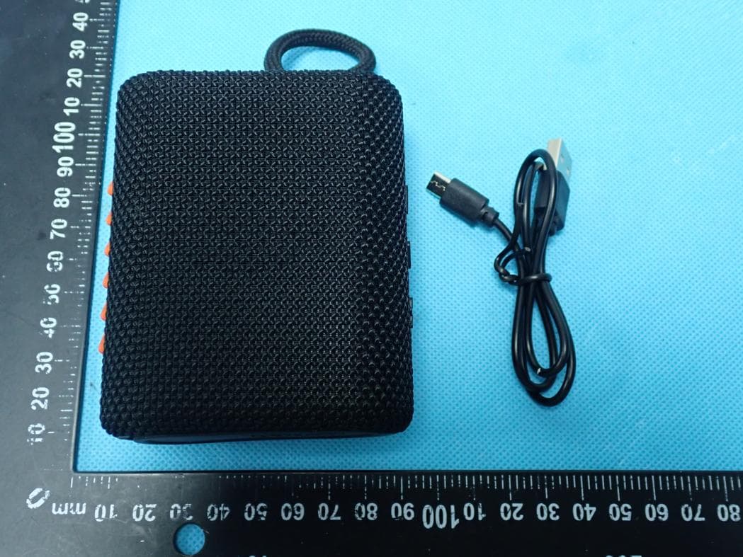
2AO47-LOWD
Jan 29, 2026Lowd R1.0
Equipment Class
DSS - Part 15 Spread Spectrum Transmitter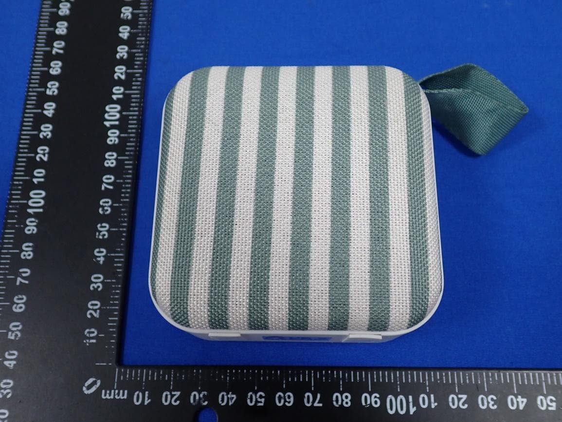
2AO47-S41TSOLI
Nov 24, 2025Portable Travel Speaker
Equipment Class
DSS - Part 15 Spread Spectrum Transmitter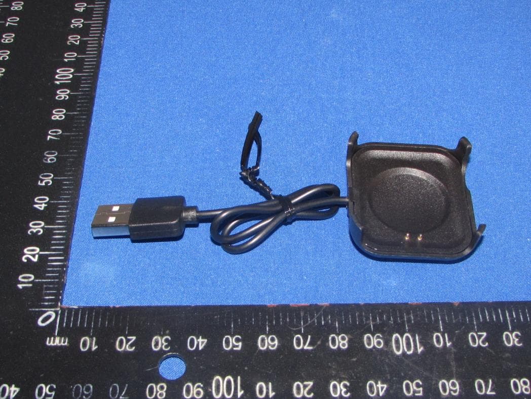
2AO47-KW39
Aug 05, 2024smart watch
Equipment Class
DSS - Part 15 Spread Spectrum Transmitter
2AO47-KM104
Oct 24, 2023Microphone Speaker
Equipment Class
DSS - Part 15 Spread Spectrum Transmitter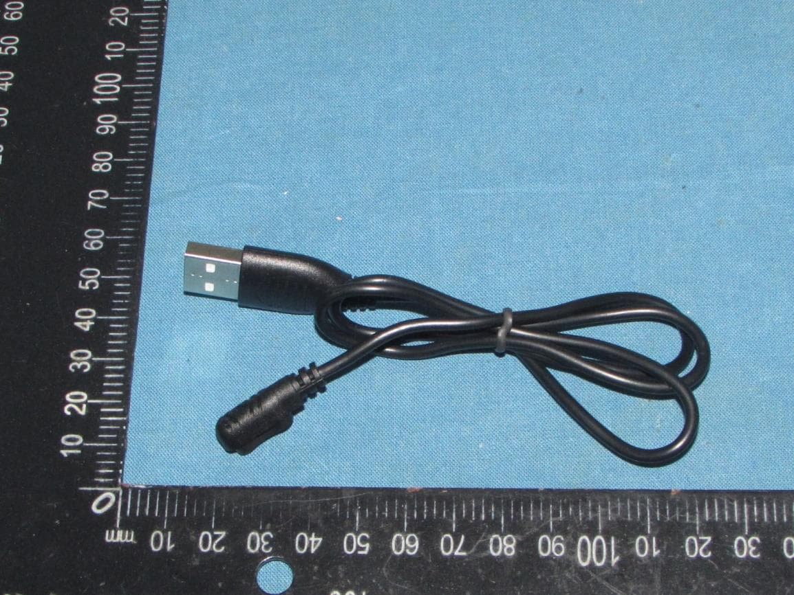
2AO47-B06
Sep 10, 2023Smart Watch
Equipment Class
DSS - Part 15 Spread Spectrum Transmitter