2AO89PG-MIC2Wireless microphone
PICOGEAR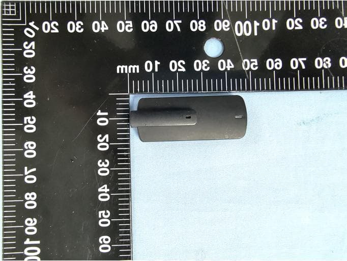
Click to zoom
Application Details
- Equipment Class
- DXX - Part 15 Low Power Communication Device Transmitter
- Date of Grant
- Dec 30, 2020
- Application Purpose
- Original Equipment
- Date of Application
- Dec 30, 2020
- Equipment Note
- Wireless microphone
- Frequency Range
- 2402.00000000 - 2480.00000000
- Company
- PICOGEAR
- Country
- France
Documents & Files
Document Text
Text extracted from the exhibit documents filed with the FCC. Open a document above to read the original.
Users Manual
FIRST USE Make sure to fully charge your PicoMic before the first use, since it may be completely discharged. Place it in your receiver charging dock, and plug your receiver to a USB power source. During the charge, the PicoMic light will flash yellow. You should charge your PicoMic at least once a month. Do not store your PicoMic for a long time with a low battery. This could significantly lower the battery capacity. After your PicoMic is fully charged, you will need to pair it with your receiver. You can choose your PicoMic to be MIC1 or MIC2. If you have two PicoMics, you can select one as MIC1 and the other one as MIC2. For this: 1. Remove all the PicoMics from the receiver. 2. 3. Follow the instructions on the screen. 4. Your PicoMic is now paired as MIC1. When you remove it from the receiver, it will automatically connect and you will be able to see the audio levels, battery level, and wireless connection status. More options are available once you enter the MIC1 menu. Follow the same procedure for your other PicoMic, to pair it as MIC2. LED INDICATION The PicoMic LED can show the following states: OFF In sleep mode (not connected) Flashing yellow Charging Green Fully charged Blue Connected as MIC1 Red Connected as MIC2 RECOMMENDED POSITIONING We recommend positioning the PicoMic as close as possible to the mouth of the speaker. If the PicoMic is too far from the mouth, it will pick up more unwanted ambient noise, making the voice less intelligible. For example, you can position it at the top of the shirt, near the collar. Best Too far away not recommended COMMON PROBLEMS Q. My receiver will not connect to the PicoMic. with your receiver. Follow the procedure above. discharged. Make sure to charge it by connecting the receiver to a USB power source. Please note that the receiver will not charge the PicoMic if it is not itself connected to a USB power source. Q. My PicoMic does not charge (no flashing yellow light). A. Make sure your receiver is connected to a USB power source. Make sure that the PicoMic charging contacts are clean you can use a small amount of rubbing alcohol to clean them if they are dirty. Q. The audio quality is not good. A. Make sure that the PicoMic gain is not too low. Usually, you should use a 0dB gain, unless you are in a very noisy environment. Make sure that your receiver gain is properly set, depending on your audio device. Check your online user manual for more information. Q. I am trying to use the PicoMic onstage, but I get feedback noise (Larsen effect) events, where the sound is immediately broadcasted - the PicoMic will pick this sound as well and it may create feedback. Generally, you will need to reduce the PicoMic gain and put it as close as possible to the speaker mouth. Use the PicoMic Pro with an external directional Lavalier microphone, or better, with an external headset microphone where the microphone is very close to the mouth. Should you need more help: Check our extensive online manual for more details: www.picogear.com/usermanual Contact us for assistance www.picogear.com/support EN SAFETY INSTRUCTIONS Contains small parts which may be a choking hazard. Not suitable for children under age 3. Do not expose this product to rain, liquids or moisture. Do not disassemble or make unauthorized alterations to this product. Use this product only with an agency approved power supply which meets local regulatory requirements (e.g., UL, CSA, VDE, CCC). Do not expose products above 50°C or 140°F. Do not apply excessive pressure on the product, do not insert anything inside the product, do not expose the product to any shock. Do not transport or use a product that has suffered a shock, has signs of damage, is heating up, or is not working properly. Do not leave a product unattended during charging. Completely charge the battery at least once each month. Do not charge a product whose battery has been empty for a long period of time. When the product is worn, keep at least a 10mm distance between the product and the skin. Please dispose of used batteries properly, following local regulations. Do not incinerate. This product must not be used near people using any life-support device, such as pacemaker, implantable defibrillator, insulin pump, etc. This symbol means the product must not be discarded as household waste, and should be delivered to an appropriate collection facility for recycling. Proper disposal and recycling helps protect natural resources, human health and the environment. For more information on disposal and recycling of this product, contact your local municipality, disposal service, or the shop where you bought this product. Removal of the rechargeable lithium ion battery in this product should be conducted only by a qualified professional. ELECTROMAGNETIC COMPLIANCE STATEMENT This device complies with Part 15 of the FCC Rules. Operation is subject to the following two conditions: (1) This device may not cause harmful interference, and (2) this device must accept any interference received, including interference that may cause undesired operation. operate this equipment. This equipment has been tested and found to comply with the limits for a Class B digital device, pursuant to part 15 of the FCC Rules. These limits are designed to provide reasonable protection against harmful interference in a residential installation. This equipment generates uses and can radiate radio frequency energy and, if not installed and used in accordance with the instructions, may cause harmful interference to radio communications. However, there is no guarantee that interference will not occur in a particular installation. If this equipment does cause harmful interference to radio or television reception, which can be determined by turning the equipment off and on, the user is encouraged to try to correct the interference by one or more of the following measures: - Reorient or relocate the receiving antenna. - Increase the separation between the equipment…
Text truncated - open the document above for the full version.
Cover Letter(s)
PICOGEAR 11 Rue de la Tombe Issoire 75014 PARIS France -------------------------------------------------------------------------------- (FCC ID:2AO89PG-MIC2) POWER OF ATTORNEY DATE: 2020-12-28 Federal Communications Commission Authorization and Evaluation Division 7435 Oakland Mills Road Columbia, MD 21046 To Whom It May Concern: We, the undersigned, hereby authorize Waltek Testing Group (Shenzhen) Co., Ltd. Jandy So on our behalf, to apply to the Federal Communications Commission on our equipment. Any and all acts carried out by Waltek Testing Group (Shenzhen) Co., Ltd. Jandy So on our behalf shall have the same effect as acts of our own. This is to advise that we are in full compliance with the Anti-Drug Abuse Act. We, PICOGEAR are not subject to a denial of federal benefits pursuant to Section 5301 of the Anti-Drug Act of 1988, 21 USC853a, and no party to the application is subject to a denial of federal benefits pursuant to that section. Sincerely, PICOGEAR ------------------------------- Florent Bouchoux/CEO
Cover Letter(s)
PICOGEAR 11 Rue de la Tombe Issoire 75014 PARIS France --------------------------------------------------------------------------------------------------------------------- Date: 2021-01-05 Federal Communications Commission Authorization and Evaluation Division 7435 Oakland Mills Road Columbia, MD 21046 FCC ID: 2AO89PG-MIC2 Confidentiality Request To whom it may concern, Pursuant to Sections 0.457 and 0.459 of the Commission’s Rules, we hereby request confidential treatment of the information accompanying this application as outlined below: Long-Term Confidentiality ☒ Block Diagram ☐ Tune-Up Information ☒ Operational Description ☐ Security Information ☒ Schematics ☐ Software Defined Radio (SDR) Information ☐ Parts List Short-term confidentiality (180 days) ☒ External Photos ☒ Test Setup Photos ☒Internal Photos ☒ User Manual The above materials contain trade secrets and proprietary information not customarily released to the public. The public disclosure of these materials may be harmful to the applicant and provide unjustified benefits to its competitors. The applicant understands that pursuant to Section 0.457 of the Rules, disclosure of this application and all accompanying documentation will not be made before the date of the Grant for this application. Sincerely, PICOGEAR ------------------------------- Florent Bouchoux/CEO
External Photos
Reference No.: WTX20X10077986W Page 2 of 11 Waltek Testing Group (Shenzhen) Co., Ltd. http://www.semtest.com.cn EXHIBIT 2 - EUT EXTERNAL PHOTOGRAPHS EUT View 1 EUT View 2 Reference No.: WTX20X10077986W Page 3 of 11 Waltek Testing Group (Shenzhen) Co., Ltd. http://www.semtest.com.cn EUT View 3 EUT View 4 Reference No.: WTX20X10077986W Page 4 of 11 Waltek Testing Group (Shenzhen) Co., Ltd. http://www.semtest.com.cn EUT View 5 EUT View 6 Reference No.: WTX20X10077986W Page 5 of 11 Waltek Testing Group (Shenzhen) Co., Ltd. http://www.semtest.com.cn EUT View 7
ID Label/Location Info
Reference No.: WTX20X10077986W Page 1 of 11 Waltek Testing Group (Shenzhen) Co., Ltd. http://www.semtest.com.cn ANNEX EXHIBIT 1 - PRODUCT LABELING Proposed FCC ID Label Format FCC ID: 2AO89PG-MIC2 Specifications: The label shall be securely affixed to a permanently attached part of the device, in a location where it is visible or easily accessible to the user, and shall not be readily detachable. The label shall be sufficiently durable to remain fully legible and intact on the device in all normal conditions of use throughout the device’s expected lifetime. Proposed Label Location on EUT FCC ID Label Location
Internal Photos
Reference No.: WTX20X10077986W Page 6 of 11 Waltek Testing Group (Shenzhen) Co., Ltd. http://www.semtest.com.cn EXHIBIT 3 - EUT INTERNAL PHOTOGRAPHS EUT Housing and Board View 1 Solder Board-Component View 1 Reference No.: WTX20X10077986W Page 7 of 11 Waltek Testing Group (Shenzhen) Co., Ltd. http://www.semtest.com.cn Solder Board-Component View 2 Solder Board-Component View 3 Reference No.: WTX20X10077986W Page 8 of 11 Waltek Testing Group (Shenzhen) Co., Ltd. http://www.semtest.com.cn Solder Board-Component View 4 Antenna View Antenna
Test Report
Waltek Testing Group (Shenzhen) Co., Ltd. http://www.semtest.com.cn Page 1 of 33 TEST REPORT Reference No. .................... : WTX20X10077986W FCC ID ................................ : 2AO89PG-MIC2 Applicant ........................... : PICOGEAR SAS Address.............................. : 11 Rue de la Tombe Issoire 75014 PARIS France Product Name ................... : Wireless microphone Test Model. ........................ : PG-MIC2 Standards .......................... : FCC Part 15.249 Date of Receipt sample .... : Oct.26, 2020 Date of Test........................ : Oct.26, 2020 to Nov.02, 2020 Date of Issue ..................... : Nov.02, 2020 Test Result ......................... : Pass Remarks: The results shown in this test report refer only to the sample(s) tested, this test report cannot be reproduced, except in full, without prior written permission of the company. The report would be invalid without specific stamp of test institute and the signatures of compiler and approver. Prepared By: Waltek Testing Group (Shenzhen) Co., Ltd. Address: 1/F., Room 101, Building 1, Hongwei Industrial Park, Liuxian 2nd Road, Block 70 Bao'an District, Shenzhen, Guangdong, China Tel.: +86-755-33663308 Fax.: +86-755-33663309 Tested by: Reviewed By: Approved & Authorized By: Jack Huang / Project Engineer Lion Cai / RF Manager Silin Chen / Manager Reference No.: WTX20X10077986W Page 2 of 33 Waltek Testing Group (Shenzhen) Co., Ltd. http://www.semtest.com.cn TABLE OF CONTENTS 1. GENERAL INFORMATION ...................................................................................................................................4 1.1 PRODUCT DESCRIPTION FOR EQUIPMENT UNDER TEST (EUT) ...............................................................................4 1.2 TEST STANDARDS ...................................................................................................................................................5 1.3 TEST METHODOLOGY .............................................................................................................................................5 1.4 TEST FACILITY .......................................................................................................................................................5 1.5 EUT SETUP AND TEST MODE .................................................................................................................................6 1.6 MEASUREMENT UNCERTAINTY ..............................................................................................................................7 1.7 TEST EQUIPMENT LIST AND DETAILS .....................................................................................................................8 2. SUMMARY OF TEST RESULTS ......................................................................................................................... 10 3. ANTENNA REQUIREMENTS .............................................................................................................................. 11 3.1 STANDARD APPLICABLE ....................................................................................................................................... 11 3.2 TEST RESULT........................................................................................................................................................ 11 4. RADIATED EMISSIONS ....................................................................................................................................... 12 4.1 STANDARD APPLICABLE ....................................................................................................................................... 12 4.2 TEST PROCEDURE ................................................................................................................................................. 12 4.3 CORRECTED AMPLITUDE & MARGIN CALCULATION ............................................................................................ 15 4.4 SUMMARY OF TEST RESULTS/PLOTS .................................................................................................................... 15 5. OUT OF BAND EMISSIONS ................................................................................................................................. 23 5.1 STANDARD APPLICABLE ....................................................................................................................................... 23 5.2 TEST PROCEDURE ................................................................................................................................................. 23 5.3 SUMMARY OF TEST RESULTS/PLOTS .................................................................................................................... 23 6. EMISSION BANDWIDTH ..................................................................................................................................... 26 6.1 STANDARD APPLICABLE ....................................................................................................................................... 26 6.2 TEST PROCEDURE ................................................................................................................................................. 26 6.3 SUMMARY OF TEST RESULTS/PLOTS .................................................................................................................... 26 7. CONDUCTED EMISSIONS .................................................................................................................................. 28 7.1 TEST PROCEDURE ................................................................................................................................................. 28 7.2 BASIC TEST SETUP BLOCK DIAGRAM ................................................................................................................... 28 7.3 TEST RECEIVER SETUP ..........................…
Text truncated - open the document above for the full version.
Test Setup Photos
Reference No.: WTX20X10077986W Page 9 of 11 Waltek Testing Group (Shenzhen) Co., Ltd. http://www.semtest.com.cn EXHIBIT 4 - TEST SETUP PHOTOGRAPHS Conducted Emission Test Setup Radiation Emission Test Setup (Below 30MHz) Reference No.: WTX20X10077986W Page 10 of 11 Waltek Testing Group (Shenzhen) Co., Ltd. http://www.semtest.com.cn Radiation Emission Test Setup (30MHz to 1GHz) Radiation Emission Test Setup (1GHz to 18GHz) Reference No.: WTX20X10077986W Page 11 of 11 Waltek Testing Group (Shenzhen) Co., Ltd. http://www.semtest.com.cn Radiation Emission Test Setup (Above 18GHz) ***** END OF REPORT *****
Contact Information
Applicant
Florent Bouchoux(CEO)
Test Firm
Waltek Testing Group (Shenzhen) Co., Ltd.Jandy So
Technical Specifications
| # | Rule Parts | Frequency Range | Power Output |
|---|---|---|---|
| 1 | 15C | 2.40 GHz - 2.48 GHz | - |