2AOE2-RD1100USB Dongle
Zhejiang Rexense IoT Technology Co., Ltd.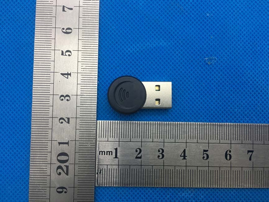
Click to zoom
Application Details
- Equipment Class
- DTS - Digital Transmission System
- Date of Grant
- Jan 13, 2020
- Application Purpose
- Original Equipment
- Date of Application
- Jan 13, 2020
- Equipment Note
- USB Dongle
- Frequency Range
- 2405.00000000 - 2480.00000000
- Country
- China
Documents & Files
Document Text
Text extracted from the exhibit documents filed with the FCC. Open a document above to read the original.
Users Manual
ZigBee/USBadopter RD1100+ 1 ZhejiangRayingIoTTechnologyCo.,Ltd Copyright Theinformationcontainedinthisdocumentistheproprietaryinformation ofZhejiangRexenseTechnologyCo.,Ltd.(hereinafterreferredasRexense). Allrightsreserved.Withoutthewrittenpermissionofthecompanymaynotto thecompany'semployees,agents,partnersorlicensingpartydisclosetoany thirdpartyotherthanthecontentofthedocument,inanyformwithout authorization,copyingordisseminationofthisdocument.Iftheuserviolates copyrightprotection,thecompanyhastherighttotheresultinglegal responsibilityshallbeinvestigatedforusers. VersionUpdate V1.0.02017/3/7Preliminary 2 CONTENT 1. Overview .................................................................................................................. 3 1.1. Supported oprating system ................................................................................ 3 2. Rated parameter ..................................................................................................... 3 3. Operating Conditions .............................................................................................. 4 4. Other data ................................................................................................................ 4 5. Firmware Upgrades...................................................................4 6. Driver Installation and Operation .......................................................................... 4 7. Custom Firmware Development ......................................................................... 10 8. Contacts ................................................................................................................. 10 3 1.Overview D1100+USBadopterhasUSB2.0standardinterfacewithpowersupply throughUSB.Itiseasytobeconnectedtomaindevice(forexample,PC,). WithUSBserialdevicedriver,themaindevicecancommunicatewithinner ZigbeemoduleviaVCOM,actuallyworksasZigBee-RS232adopter.Thereis innerenhancedZigbeemoduleintheadopter,whichisusuallyusedwithPC andforthefiledadjustmentorpresentation. 1.1.1.1SupportedOperatingSystems •Windows98SE •WindowsXP •Windows2000 •Windows7 •MACOS-9 •MACOS-X •Linux 2.RatedParameters ParameterMinMaxUnit Testing condition SupplyVoltage Vdd 3.05.25V Voltageonany pin -0.33.6V Storage Temperature -55125°C Table1:Absolutemaximumratings Notes:Theabsolutemaximumratingsgivenaboveshouldunderno circumstancesbeviolated.Exceedingoneormoreofthelimitingvaluesmay causepermanentdamagetothedevice. 4 3.OperatingConditions Typicalvaluesat5V25°C. ParameterRangeUnit Current(TX) 125mA Current(RX) 36.0mA Ambienttemperature25°C Max.Outputpower-9to+19.5dBm RXSensitivity-98to-100dBm MaxRFDataRate250Kbps Table2:OperatingCondition 4.Otherdata Forfurthertechnicalinformation,includingradioperformance,pleasereferto theProductManualofREX3SPModuleatwww.rexense.com. FormoreinformationonZigBee®complianceandtheATcommandinterface firmware,pleaserefertothelatestATcommanddictionaryandtheREX3SP userguideatwww.rexense.com. 5.DriverInstallationandOperation Usersneedtodownloadthedrivernamed “CP210x_VCP_Win_XP_S2K3_Vista_7“atwww.rexense.com.After successfulinstallation,thesystemwillcreateaVCOMport,throughwhichthe systemcanaccesstotheserialportofthemoduleREX3SP.Formore informationofthemodule(REX3SP),pleasegotowww.rexense.comto downloaddocuments. “CP210x_VCP_Win_XP_S2K3_Vista_7”driverInstallation: 5 6.1Windows9x/XP/2k/7driverinstallation Referstopictureabove,press“Next”tocontinue; 6 Referstopictureabove,press“Next”tocontinue; Referstopictureabove,select“Iacceptthetermsofthelicenseagreement”to continue; 7 Referstopictureabove,press“Next”tocontinue; Selectdestinationfolderforthethedriver,press“Next”tocontinue; 8 Press“Install”tocontinue; 9 Whenthepicturebelowcomes,thesystemwillnotethattheinstallationdocuments, CP210x_VCP_Win_XP_S2K3_Vista_7,havebeencopiedtotheuser’sharddisk successfully.PleasepressLaunchtheCP210xVCPDriverInstallertofinishedthe installation. Click“Finish”,thedialogboxbelowcomes; Click“Install”tocompletetheinstallationofdriver. 10 7. Custom Firmware Development There are two ways of custom firmware development available: Through the USB-Serial port, users are able to update IAP upgrade on the base that there is Bootloader program in the ZigBee module. Users can send the firmware to perform the upgrade according to the upgrading commands of the Bootloader program. User can upgrade command according to BootLoader and via sending firmware program. Or, when there is no BootLoader program inside module, development tool Jlink and Stack of EFR32 are needed. Through commander of SILABS, firmware program is able to be burned to EFR32 chips of the module or downloaded via IAR for ARM developing environment. 8. Contact Us ZH EJIANG REXENSE TECHNOLOGY CO., LTD Address: Room 105, No.7 Cuibai Road, Xihu District, Hangzhou 310012 P.R.China. Tel: +86-571-85395623 Fax: +86-571-87987620 Website:www.rexense.com E-mail:[email protected]; [email protected] FCC WARNING STATEMENT Changes or modifications not expressly approved by the party responsible for compliance could void the user’s authority to operate the equipment. This equipment has been tested and found to comply with the limits for a Class B digital device, pursuant to Part 15 of the FCC Rules. These limits are designed to provide reasonable protection against harmful interference in a residential installation. This equipment generates uses and can radiate radio frequency energy and, if not installed and used in accordance with the instructions, may cause harmful interference to radio communications. However, there is no guarantee that interference will not occur in a particular installation. If this equipment does cause harmful interference to radio or television reception, which can be determined by turning the equipment off and on, the user is encouraged to try to correct the interference by one or more of the following measures: ‐‐ Reorient or relocate the receiving antenna. ‐‐ Increase the separation between the equipment and receiv…
Text truncated - open the document above for the full version.
Cover Letter(s)
D ate: Dec. 26, 2019 Equipment Autorisation Division Federal Communications Commission 7435 Oakland Mills Road Columbia, MD 21046 FCC ID: 2AOE2-RD1100 Product Name: USB Dongle Request for Confidentiality P ursuant to Sections 0.457 and 0.459 of the commission’s rules, we hereby request that the following documents be held confidential: ( List here the documents for which you are seeking confidentiality – for example ...) •Sc hematics and BOM •Block diagram •Operation description T hese materials contain trade secrets and proprietary information and are not customarily released to the public. The public disclosure of this information might be harmful to the company and provide unjustified benefits to our competitors. < Signature> N ame: Zhishun Wu Title: Sales Manager Company: Zhejiang Raying loT Technology Co., Ltd.
External Photos
M/N: RD1100+ M/N: RD1100+ M/N: RD1100+
ID Label/Location Info
FCC ID LABEL: Lab el Location: FCC ID: 2AOE2-RD1100 Pr oduct name: USB Dongle Model No.: RD1100+ Long:1cm Width: 0.5 cm
Internal Photos
M/N: RD1100+ M/N: RD1100+ M/N: RD1100+ PCB Ant.
RF Exposure Info
RF Exposure evaluation According to 447498 D01 General RF Exposure Guidance v05 The 1-g and 10-g SAR test exclusion thresholds for 100 MHz to 6 GHz at test separation distances ≤ 50 mm are determined by: [(max. power of channel, including tune-up tolerance, mW)/(min. test separation distance, mm)] ·[√ f(GHz)] ≤ 3.0 for 1-g SAR and ≤ 7.5 for 10-g extremity SAR, where f(GHz) is the RF channel transmit frequency in GHz Power and distance are rounded to the nearest mW and mm before calculation The result is rounded to one decimal place for comparison Worse case is as below: [2445 MHz 7.538 dBm(5.6728 mW)output power] (5.6728 mW /5mm) ·[√2.4 45(GHz)]= 1.774 <3.0 for 1-g SAR Then SAR evaluation is not required
Test Report
Global United Technology Services Co., Ltd. Report No.: GTS201912000114F01 Authorized Signature: Robinson Lo Laboratory Manager This results shown in this test report refer only to the sample(s) tested, this test report cannot be reproduced, except in full, without prior written permission of the company. The report would be invalid without specific stamp of test institute and the signatures of compiler and approver. Page 1 of 38 TEST Report Applicant: Zhejiang Raying loT Technology Co., Ltd. Address of Applicant: 10F, North of Building No.10, Wellong Science & Technology Park, No.88 Jiangling Road, Binjiang District, Hangzhou, 310051 China Manufacturer: Zhejiang Raying loT Technology Co., Ltd. Address of Manufacturer: 10F, North of Building No.10, Wellong Science & Technology Park, No.88 Jiangling Road, Binjiang District, Hangzhou, 310051 China Equipment Under Test (EUT) Product Name: Model No.: FCC ID: Applicable standards: USB Dongle RD1100+ 2AOE2-RD1100 FCC CFR Title 47 Part 15 Subpart C Section 15.247 Date of sample receipt: Dec 03, 2019 Date of Test: Dec 03, 2019- Dec 10, 2019 Date of report issued: Dec 10, 2019 Test Result : PASS * * In the configuration tested, the EUT complied with the standards specified above. Report No.: GTS201912000114F01 Global United Technology Services Co., Ltd. No. 123-128, Tower A, Jinyuan Business Building, No.2, Laodong Industrial Zone, Xixiang Road, Baoan District, Shenzhen, Guangdong, China 518102 Telephone: +86 (0) 755 2779 8480 Fax: +86 (0) 755 2779 8960 Page 2 of 38 2 Version Version No. Date Description 00 Dec 10, 2019 Original Prepared By: Date: Dec 10, 2019 Project Engineer Check By: Date: Dec 10, 2019 Reviewer Report No.: GTS201912000114F01 3 Contents Page 1 COVER PAGE ......................................................................................................................................... 1 2 VERSION ................................................................................................................................................. 2 3 CONTENTS ............................................................................................................................................. 3 4 TEST SUMMARY .................................................................................................................................... 4 5 GENERAL INFORMATION ..................................................................................................................... 5 5.1 GENERAL DESCRIPTION OF EUT ........................................................................................................ 5 5.2 TEST MODE ....................................................................................................................................... 7 5.3 DESCRIPTION OF SUPPORT UNITS ....................................................................................................... 7 5.4 TEST FACILITY................................................................................................................................... 7 5.5 TEST LOCATION ................................................................................................................................ 7 6 TEST INSTRUMENTS LIST .................................................................................................................... 8 7 TEST RESULTS AND MEASUREMENT DATA ................................................................................... 10 7.1 ANTENNA REQUIREMENT .................................................................................................................. 10 7.2 CONDUCTED EMISSIONS .................................................................................................................. 11 7.3 CONDUCTED PEAK OUTPUT POWER ................................................................................................. 14 7.4 CHANNEL BANDWIDTH ..................................................................................................................... 15 7.5 POWER SPECTRAL DENSITY ............................................................................................................. 17 7.6 BAND EDGES ................................................................................................................................... 19 7.6.1 Conducted Emission Method .................................................................................................... 19 7.6.2 Radiated Emission Method ....................................................................................................... 21 7.7 SPURIOUS EMISSION ........................................................................................................................ 24 7.7.1 Conducted Emission Method .................................................................................................... 24 7.7.2 Radiated Emission Method ....................................................................................................... 26 8 TEST SETUP PHOTO ........................................................................................................................... 34 9 EUT CONSTRUCTIONAL DETAILS ..................................................................................................... 36 Global United Technology Services Co., Ltd. No. 301-309, 3/F., Jinyuan Business Building, No.2, Laodong Industrial Zone, Xixiang Road, Baoan District, Shenzhen, Guangdong, China 518102 Telephone: +86 (0) 755 2779 8480 Fax: +86 (0) 755 2779 8960 Page 3 of 38 Report No.: GTS201912000114F01 4 Test Summary Test Item Section in CFR 47 Result Antenna requirement 15.203/15.247 (c) Pass AC Power Line Conducted Emission 15.207 Pass Conducted Peak Output Power 15.247 (b)(3) Pass Channel Bandwidth 15.247 (a)(2) Pass Power Spectral Density 15.247 (e) Pass Band Edge 15.247(d) Pass Spurious Emission 15.205/15.209 Pass Remark: Test according to ANSI C63.10:2013. Pass: The EUT complies with the esse…
Text truncated - open the document above for the full version.
Test Setup Photos
M/N: RD1100+ Radiated Emission test M/N: RD1100+ Conducted Emission test
Contact Information
Applicant
Zhishun Wu(Sales Manager)
Test Firm
Global United Technology Services Co. Ltd.Robinson Lo
Technical Specifications
| # | Rule Parts | Frequency Range | Power Output |
|---|---|---|---|
| 1 | 15C | 2.40 GHz - 2.48 GHz | 5.67 mW |
Other Applications from Zhejiang Rexense IoT Technology Co., Ltd.
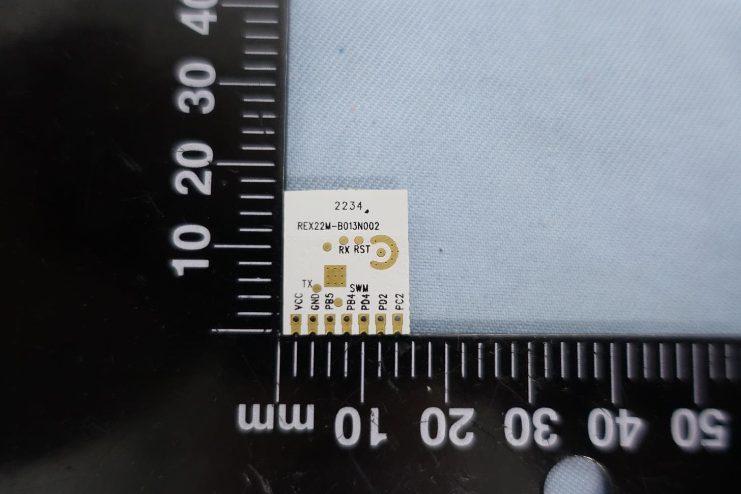
2AOE2REX3GT581
Dec 15, 20222.4G Zigbee Module
Equipment Class
DTS - Digital Transmission System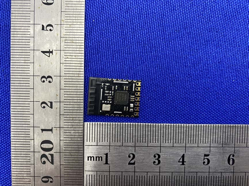
2AOE2-REX3T
May 08, 2020Zigbee
Equipment Class
DTS - Digital Transmission System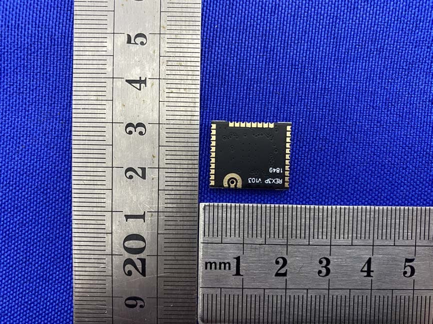
2AOE2-REX3P
May 05, 2020Zigbee module
Equipment Class
DTS - Digital Transmission System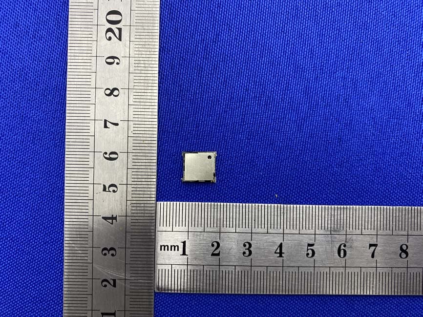
2AOE2-REX3M
May 01, 2020Zigbee module
Equipment Class
DTS - Digital Transmission System