2AOEC-T22True wireless Bluetooth headset
Shenzhen Yanhuizhongchuang Electronics Co., Ltd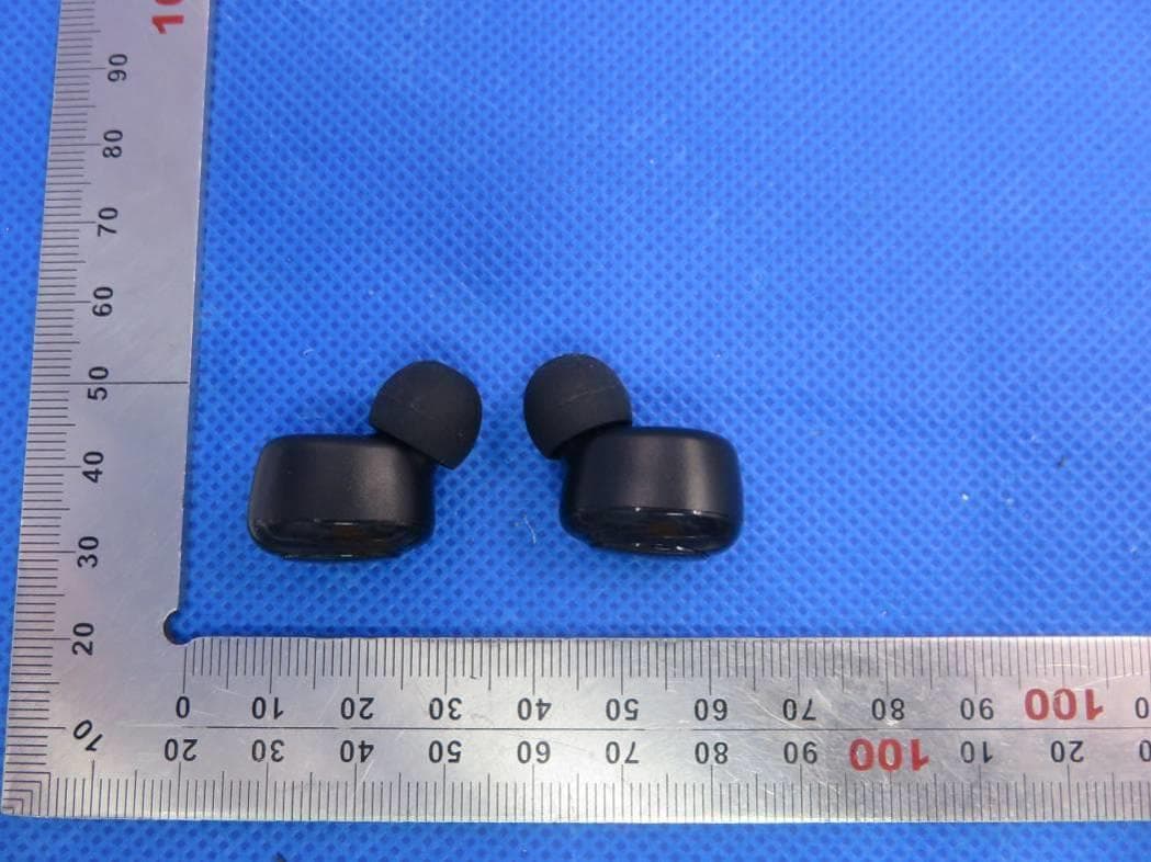
Click to zoom
Application Details
- Equipment Class
- DSS - Part 15 Spread Spectrum Transmitter
- Date of Grant
- Mar 30, 2020
- Application Purpose
- Original Equipment
- Date of Application
- Mar 30, 2020
- Equipment Note
- True wireless Bluetooth headset
- Frequency Range
- 2402.00000000 - 2480.00000000
- Country
- China
Documents & Files
Document Text
Text extracted from the exhibit documents filed with the FCC. Open a document above to read the original.
Users Manual
T22 User Manual TWS Wireless Earbuds Product display 3 1 2 6 4 5 7 ① Charging Pins Wearing style 1. Our innovative design feature 3 sizing options for great fit and wearing comfort. Please use whatever size option is most comfortable for you (S,M,L) and read the steps below. 2. Make sure the (R)(L) symbol is facing down (indicator light is facing down) then place earbuds into ear. Rotate the earbuds until it fits snugly and is comfortable. M S Specification Product Name T22 Wireless Version V5.0 Operation Range ≤ 10 meters(UnobstructedEffective Range) Earbud Charging Time about 1.5 hours Charging Case Charging Time about 2 hours Play Time 4 Hours (at 75% volume) Talk Time 3.5 Hours (at 75% volume) Stand Time 60 Hours Bluetooth Profiles A2DP,AVRCPHFP,HSP Earbud Battery Type 40mAh Rechargeable Lithium Batteries Charging Case Battery Type 350mAh Rechargeable Lithium Batteries Power on: 1. Take out the earbuds from the charging case , the earbuds will power on automatically. 2. If earbuds were not in the charging case and powered How to pair Quick start for initial use: 1. Take out the earbuds from the charging case the earbuds will turn on automatically, and then into pairing mode(the Left earbud will flashes white and blue alternately;the right earbud flashes blue slowly),you will hear the voice prompt “power on” ,then voice “Left channel” “Right channel” from both earbuds. Power On 2. Turn on bluetooth on your phone and search “T22”, then click connect. You will hear a voice “connected” once connected. Next time use: 1. The earbuds TWS T22 will remember the last device it has connected. 2. The next time when take out the earbuds from the charging case, it will automatically reconnect to your last device. 3. If it fails, please put them back into the charging case and close the charging case, thenfollow “Quick start for initial use steps” to reconnect. 4. If no device is connected, earbuds will automatically turn off after 6 minutes. How to reset (Rest your earphones if you can hear one side only) 1. Remove T22 from your list of Bluetooth devices. 2. Turn off the Bluetooth function of the Bluetooth device. 3. Put the two earbuds back into the charging case, press and hold the left and right earbud function buttons for 5 seconds, the blue LED above the earbuds flashes 3 times, indicating 1. When the battery is low,there is a voice prompt to remind you of a low battery. 2. Place both earphones into charging case and they will automatically enter into charging mode. the earbuds indicator will flash white when charging, will lights off when fully charged. Type - C 2. The charging case LED director will flash blue when charging, and keep lighting when fullycharged. (Please check battery level and charging status as indicated below. ) Basic Operation Single press on function button Play/Pause music Answer/End phone calls Double press Activate/Stop Siri Press function button 2s Play next song(right one )/previous(left one) Reject a phone call Switch Device During a call, press the either earbud button for 3 times to switch chat between the earbud and your phone. SINGER PRESS Music-Play/Pause PRESS AND HOLD 2 SECONDS(Left earbud) Previous song PRESS AND HOLD 2 SECONDS(Right earbud) FAQ Customer Support 1. Reach us directly at the email address: [email protected] 2. By order placed Your account -- Find order id -- Sold by -- Ask question --Okay Please attach the below information on email for us to quickly resolve the problem. | Your Order ID | Your Phone Model,tablet model, etc. | Your problem,show by some pictures or a video Thank you for choosing T22. We hope you are happy with the purchase. If not, you are more than welcome to contact us: [email protected] More information and promotions, Please follow us on Facebook: Contact Email: [email protected] Thank you for choosing the T22 Truly Wireless Earbuds. Please read this user manual carefully and keep it for future reference. ② Charging case LED Indicator ③ TYPE C Charging Port ④ Multi-function Button ⑤ Earbuds Indicator ⑥ Charging Contact Point ⑦ Ear tips 1 off, you need to hold and press the function buttons for 2 seconds of both earbuds to power on. Power off: L 1. Earbuds will automatically power off and recharge when R put in the charging case. 2. When the earbuds are power on,hold and press both of the earbuds function button for 5 seconds, they will power off and prompt a “Power off ” voice. (White LED light flashes 3 times) 2 3 4 the pairing has been cleared. 4. Take out earbuds from the charging case, the earbuds will automatically turn on, you will hear the voice prompt of “power on and pairing”, and then quick click the multi-function buttons on earphone 2 times to pair each other. 5. Turn on Bluetooth on your phone, Select“T22” to pair. 5 6 Charging The Charging Case 1. We suggest to use the original Type-C cable (Included in package) and power supply with 5V/1A supply for optimum charging performance. 7 Next song SINGER PRESS Answer/End Calls PRESS AND HOLD 2 SECONDS Reject Call DOUBLE PRESS Activate/Stop Siri 8 9 https://m.facebook.com/Pasonomi/ 10 11 Power on & off * Note:Please remove the protective tape on each earphone before use. *Note: If you do not know how to do it, please contact us by email to get the operation video. *Note: Please make sure the charging case has enough power. Problem type Reason Solution Doesn’t charging /Stop working Charging case out of battery or the earbuds fail to connect the charging with case. Charge the case first,Gently swing the earbuds to make it contact with the charging pins in the charging case. Work individually Left one and right one doesn’t pair LeftPlease refer the reset option and reset them. Sound imbalance Dust block Please clean the earbuds first Can’t turn on the earbuds Low battery (A1) Check whether the charging case or earbud has enough power. (A2) Put the earbuds back to the charging case to fully charge and try to turn on again. Pairing does not work Pairing Wrong Put both…
Text truncated - open the document above for the full version.
External Photos
External Photos TOTAL VIEW OF EUT Headset TOP VIEW OF EUT BOTTOM VIEW OF EUT FRONT VIEW OF EUT BACK VIEW OF EUT LEFT VIEW OF EUT RIGHT VIEW OF EUT VIEW OF EUT(PORT) Charging Dock TOP VIEW OF EUT BOTTOM VIEW OF EUT FRONT VIEW OF EUT BACK VIEW OF EUT LEFT VIEW OF EUT RIGHT VIEW OF EUT
ID Label/Location Info
FCC ID Label Location FCC ID: 2AOEC-T22
Internal Photos
Internal Photos Right OPEN VIEW OF EUT VIEW OF BATTERY INTERNAL VIEW OF EUT-1 INTERNAL VIEW OF EUT-2 BT Antenna INTERNAL VIEW OF EUT-3 Left OPEN VIEW OF EUT VIEW OF BATTERY INTERNAL VIEW OF EUT-1 BT Antenna INTERNAL VIEW OF EUT-2 INTERNAL VIEW OF EUT-3 VIEW OF EUT(PORT)-1 VIEW OF EUT(PORT)-2 OPEN VIEW OF EUT VIEW OF BATTERY INTERNAL VIEW OF EUT-1 INTERNAL VIEW OF EUT-2
Test Report
Page 1 of 74 FCC Test Report Report No.: AGC00690200301FE03 FCC ID : 2AOEC-T22 APPLICATION PURPOSE : Original Equipment PRODUCT DESIGNATION : True wireless Bluetooth headset BRAND NAME : N/A MODEL NAME : T22, K16, T26, T28, T29, T23 APPLICANT : Shenzhen Yanhuizhongchuang Electronics Co.,Ltd. DATE OF ISSUE : Mar. 23, 2020 STANDARD(S) : FCC Part 15.247 REPORT VERSION : V1.0 Attestation of Global Compliance (Shenzhen) Co., Ltd CAUTION: This report shall not be reproduced except in full without the written permission of the test laboratory and shall not be quoted out of context. Report No.: AGC00690200301FE03 Page 2 of 74 REPORT REVISE RECORD Report Version Revise Time Issued Date Valid Version Notes V1.0 / Mar. 23, 2020 Valid Initial Release Report No.: AGC00690200301FE03 Page 3 of 74 TABLE OF CONTENTS 1. VERIFICATION OF CONFORMITY ............................................................................................................... 5 2. GENERAL INFORMATION ............................................................................................................................ 6 2.1. PRODUCT DESCRIPTION ..................................................................................................................... 6 2.2. TABLE OF CARRIER FREQUENCYS ..................................................................................................... 6 2.3. RECEIVER INPUT BANDWIDTH ............................................................................................................ 7 2.4. EXAMPLE OF A HOPPING SEQUENCY IN DATA MODE ....................................................................... 7 2.5. EQUALLY AVERAGE USE OF FREQUENCIES AND BEHAVIOUR ........................................................ 7 2.6. RELATED SUBMITTAL(S) / GRANT (S) .................................................................................................. 8 2.7. TEST METHODOLOGY .......................................................................................................................... 8 2.8. SPECIAL ACCESSORIES ....................................................................................................................... 8 2.9. EQUIPMENT MODIFICATIONS .............................................................................................................. 8 3. MEASUREMENT UNCERTAINTY ................................................................................................................. 9 4. DESCRIPTION OF TEST MODES ............................................................................................................... 10 5. SYSTEM TEST CONFIGURATION .............................................................................................................. 11 5.1. CONFIGURATION OF EUT SYSTEM .................................................................................................... 11 5.2. EQUIPMENT USED IN TESTED SYSTEM ............................................................................................. 11 5.3. SUMMARY OF TEST RESULTS ............................................................................................................. 11 6. TEST FACILITY ........................................................................................................................................... 12 7. PEAK OUTPUT POWER ............................................................................................................................. 13 7.1. MEASUREMENT PROCEDURE ........................................................................................................... 13 7.2. TEST SET-UP (BLOCK DIAGRAM OF CONFIGURATION) ................................................................... 13 7.3. LIMITS AND MEASUREMENT RESULT ............................................................................................... 14 8. 20DB BANDWIDTH ..................................................................................................................................... 20 8.1. MEASUREMENT PROCEDURE ........................................................................................................... 20 8.2. TEST SET-UP (BLOCK DIAGRAM OF CONFIGURATION) ................................................................... 20 8.3. LIMITS AND MEASUREMENT RESULTS ............................................................................................. 20 9. CONDUCTED SPURIOUS EMISSION ........................................................................................................ 27 9.1. MEASUREMENT PROCEDURE ........................................................................................................... 27 9.2. TEST SET-UP (BLOCK DIAGRAM OF CONFIGURATION) ................................................................... 27 9.3. MEASUREMENT EQUIPMENT USED .................................................................................................. 27 9.4. LIMITS AND MEASUREMENT RESULT ............................................................................................... 27 10. RADIATED EMISSION ............................................................................................................................... 37 Report No.: AGC00690200301FE03 Page 4 of 74 10.1. MEASUREMENT PROCEDURE ......................................................................................................... 37 10.2. TEST SETUP ....................................................................................................................................... 39 10.3. LIMITS AND MEASUREMENT RESULT ............................................................................................. 40 10.4. TEST RESULT ..................................................................................................................................... 40 11. NUMBER OF HOPPING FREQUENCY .............................................................................................…
Text truncated - open the document above for the full version.
Test Report
Report No.: AGC00690200301FE03 Page 51 of 74 12. TIME OF OCCUPANCY (DWELL TIME) 12.1. MEASUREMENT PROCEDURE The EUT shall have its hopping function enabled. Use the following spectrum analyzer settings: 1. Span: Zero span, centered on a hopping channel. 2. RBW shall be≤channel spacing and where possible RBW should be set >> 1 / T, where T is the expected dwell time per channel. 3. Sweep: As necessary to capture the entire dwell time per hopping channel; where possible use a video trigger and trigger delay so that the transmitted signal starts a little to the right of the start of the plot. The trigger level might need slight adjustment to prevent triggering when the system hops on an adjacent channel; a second plot might be needed with a longer sweep time to show two successive hops on a channel. 4. Detector function: Peak. Trace: Max hold. 5. Use the marker-delta function to determine the transmit time per hop. 6. Repeat the measurement using a longer sweep time to determine the number of hops over the period specified in the requirements. The sweep time shall be equal to, or less than, the period specified in the requirements. Determine the number of hops over the sweep time and calculate the total number of hops in the period specified in the requirements, using the following equation: (Number of hops in the period specified in the requirements) = (number of hops on spectrum analyzer) × (period specified in the requirements / analyzer sweep time) 7. The average time of occupancy is calculated from the transmit time per hop multiplied by the number of hops in the period specified in the requirements. 12.2. TEST SETUP (BLOCK DIAGRAM OF CONFIGURATION) Same as described in section 8.2 12.3. MEASUREMENT EQUIPMENT USED The same as described in section 6 12.4. LIMITS AND MEASUREMENT RESULT Channel Time of Pulse for DH5 (ms) Number of hops in the period specified in the requirements Sweep Time (ms) Limit (ms) Low 2.875 28*4 322.000 400 Middle 2.842 25*4 284.200 400 High 2.867 30*4 344.040 400 Note: The 8DPSK modulation is the worst case and recorded in the report. Report No.: AGC00690200301FE03 Page 52 of 74 TEST PLOT OF LOW CHANNEL Report No.: AGC00690200301FE03 Page 53 of 74 TEST PLOT OF MIDDLE CHANNEL Report No.: AGC00690200301FE03 Page 54 of 74 TEST PLOT OF HIGH CHANNEL Report No.: AGC00690200301FE03 Page 55 of 74 13. FREQUENCY SEPARATION 13.1. MEASUREMENT PROCEDURE The EUT shall have its hopping function enabled. Use the following spectrum analyzer settings: 1. Span: Wide enough to capture the peaks of two adjacent channels. 2. RBW: Start with the RBW set to approximately 30% of the channel spacing; adjust as necessary to best identify the center of each individual channel. 3. Video (or average) bandwidth (VBW) ≥ RBW. 4. Sweep: Auto. e) Detector function: Peak. f) Trace: Max hold. g) Allow the trace to stabilize. Use the marker-delta function to determine the separation between the peaks of the adjacent channels. 13.2. TEST SETUP (BLOCK DIAGRAM OF CONFIGURATION) Same as described in section 6.2 13.3. MEASUREMENT EQUIPMENT USED The same as described in section 6.3 13.4. LIMITS AND MEASUREMENT RESULT CHANNEL CHANNEL SEPARATION KHz LIMIT (KHz) RESULT CH01-CH02 995 >=25 KHz or 2/3 20 dB BW PASS TEST PLOT FOR FREQUENCY SEPARATION Note: The 8DPSK modulation is the worst case and recorded in the report. Report No.: AGC00690200301FE03 Page 56 of 74 14. FCC LINE CONDUCTED EMISSION TEST 14.1. LIMITS OF LINE CONDUCTED EMISSION TEST Frequency Maximum RF Line Voltage Q.P.( dBuV) Average( dBuV) 150kHz~500kHz 66-56 56-46 500kHz~5MHz 56 46 5MHz~30MHz 60 50 Note: 1. The lower limit shall apply at the transition frequency. 2. The limit decreases linearly with the logarithm of the frequency in the range 0.15 MHz to 0.50 MHz. 14.2. BLOCK DIAGRAM OF LINE CONDUCTED EMISSION TEST EUT & Support Units Report No.: AGC00690200301FE03 Page 57 of 74 14.3. PRELIMINARY PROCEDURE OF LINE CONDUCTED EMISSION TEST 1. The equipment was set up as per the test configuration to simulate typical actual usage per the user’s manual. When the EUT is a tabletop system, a wooden table with a height of 0.8 meters is used and is placed on the ground plane as per ANSI C63.10 (see Test Facility for the dimensions of the ground plane used). When the EUT is a floor-standing equipment, it is placed on the ground plane which has a 3-12 mm non-conductive covering to insulate the EUT from the ground plane. 2. Support equipment, if needed, was placed as per ANSI C63.10. 3. All I/O cables were positioned to simulate typical actual usage as per ANSI C63.10. 4. All support equipments received AC120V/60Hz power from a LISN, if any. 5. The EUT received DC charging voltage by adapter which received AC120V/60Hz power by a LISN. 6. The test program was started. Emissions were measured on each current carrying line of the EUT using a spectrum Analyzer / Receiver connected to the LISN powering the EUT. The LISN has two monitoring points: Line 1 (Hot Side) and Line 2 (Neutral Side). Two scans were taken: one with Line 1 connected to Analyzer / Receiver and Line 2 connected to a 50 ohm load; the second scan had Line 1 connected to a 50 ohm load and Line 2 connected to the Analyzer / Receiver. 7. Analyzer / Receiver scanned from 150 kHz to 30MHz for emissions in each of the test modes. 8. During the above scans, the emissions were maximized by cable manipulation. 9. The test mode(s) were scanned during the preliminary test. Then, the EUT configuration and cable configuration of the above highest emission level were recorded for reference of final testing. 14.4. FINAL PROCEDURE OF LINE CONDUCTED EMISSION TEST 1. EUT and support equipment was set up on the test bench as per step 2 of the preliminary test. 2. A scan was taken on both power lines, Line 1 and Line 2, recording at least the six highest emissions. Emission frequency and amplitude were recorded into a computer in which correction factors were used to calculate the emission level and compare readi…
Text truncated - open the document above for the full version.
Test Setup Photos
Test Setup Photos RADIATED EMISSION TEST SETUP BELOW 1GHZ RADIATED EMISSION TEST SETUP ABOVE 1GHZ CONDUCTED TEST SETUP
Contact Information
Applicant
Jiquan Yu
Test Firm
Attestation of Global Compliance (Shenzhen) Co., LDoris Li
[email protected]+86-755-25234088
Technical Specifications
| # | Rule Parts | Frequency Range | Power Output |
|---|---|---|---|
| 1 | 15C | 2.40 GHz - 2.48 GHz | 2.00 mW |
Other Applications from Shenzhen Yanhuizhongchuang Electronics Co., Ltd

2AOEC-T31
May 06, 2021Bluetooth True Wireless Stereo Earbuds
Equipment Class
DSS - Part 15 Spread Spectrum Transmitter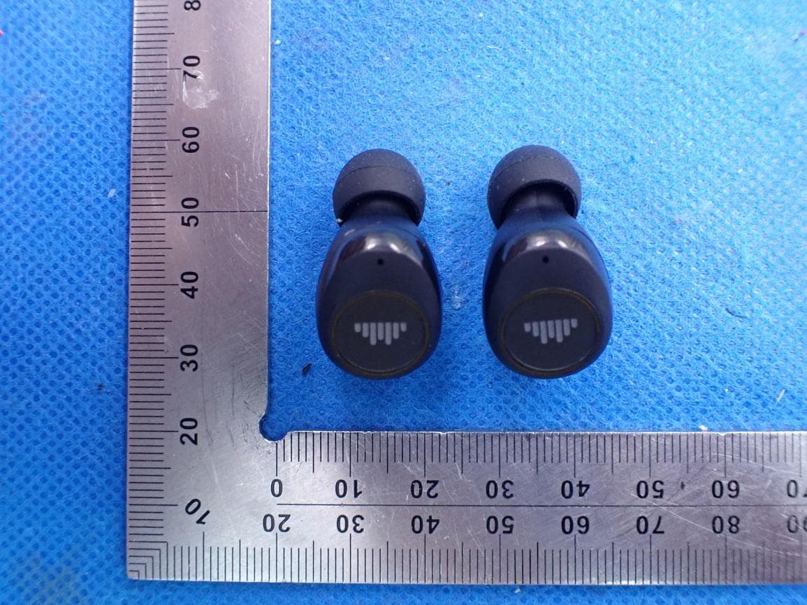
2AOEC-T33
Apr 26, 2021Bluetooth True Wireless Stereo Earbuds
Equipment Class
DTS - Digital Transmission System