Text extracted from the exhibit documents filed with the FCC. Open a document above to read the original.
1 PROGLOVE USER MANUAL Technical document SAFETY INSTRUCTIONS Hardware ..................................................................... 5Wearables .................................................................... 5 SCOPE OF DELIVERY Hardware & Wearables ............................................... 6 TECHNICAL PROPERTIES Scanner ........................................................................ 7Connectivity Device .................................................... 10Charging Station ........................................................ 13Wearables .................................................................. 15 COMPATIBILITY MATRIX Compatibility Matrix .................................................. 17 SETUP OF PROGLOVE SYSTEM 1 st step: Charge Scanner ............................................ 18 2 nd step: Connect via Connectivity Device ................ 18 3 rd step: Switch on Scanner ....................................... 20 4 th step: Connect Scanner.......................................... 20 5 th step: Scan ............................................................. 26 6 th step: Disconnect ProGlove System ...................... 27 7 th step: Release Scanner from Wearables .............. 31 CONFIGURE DEVICES AND FIRMWARE UPDATE 1 st WXIT3TIRMRKGSRƼKYVEXMSRW .............................. 32 2 nd WXIT'VIEXIERI[GSRƼKYVEXMSR ........................ 32 3 rd WXIT'SRRIGXMZMX]GSRƼKYVEXMSR ......................... 32 4 th step: Device settings ............................................. 33 5 th step: Symbology settings .................................... 33 6 th WXIT;SVOƽS[VYPIW ............................................ 33 7 th WXIT'SRƼKYVIHIZMGIWERH*MVQ[EVI9THEXI ... 34 SIGNAL TABLE General Scanner ........................................................ 36Connection via Access Point .................................... 37 PROGLOVE USER MANUAL 8%&0)3*'328)287 Connection via BLE .................................................... 37MARK Display ............................................................. 38Gateway ...................................................................... 41 STORAGE AND CLEANING Storage location and temperature ........................... 43Cleaning Hardware .................................................... 43Cleaning Wearables ................................................... 43 SOLUTION TO THE PROBLEM Scanner ....................................................................... 44Access Point - Data transfer ..................................... 46BLE - Data transfer ..................................................... 47Gateway - Data transfer ............................................. 48Charging Station ........................................................ 49,EVH6IWIX *EGXSV](IJEYPX&EVGSHI .................... 49 DISPOSAL ........................................................... 50 DIRECTIVES & CERTIFICATION .........50 SUPPORT Technical support contact data ............................... 45Sales contact data .................................................... 45 *92'8-323*8,-7(3'91)28 This user manual contains a system overview, technical data about the Hardware and Wearables, detailed step-by-step instructions for using ProGlove system and infor-QEXMSREFSYXGSRƼKYVEXMSRWIXXMRKWERHXVSYFPIWLSSXMRK-XMWMRXIRHIHJSVTVSGIWWTPERRIVWGSRƼKYVEXSVWERHmaintenance technicians who are using ProGlove system JSVXLIƼVWXXMQI-XMWHIWMKRIHWSXLEX4VS+PSZIW]WXIQcan be used safely without prior knowledge. Read carefully before use and keep for future reference. ADDRESS: ;SVOEVSYRH+QF, 4VS+PSZI-RGBuilding 64.08a 520 W. Erie St. Rupert-Mayer-Str. 44 Suite 400 1YRMGL 'LMGEKS-0 USA ProGlove Ltd.Coventry University Technology ParkPuma Way, Coventry CV1 2TT, UK United Kingdom DOCUMENT TITLE: ProGlove User Manual DATE OF PUBLICATION: 07/2022 VERSION: 4.0 ABOUT THESE OPERATING INSTRUCTIONS EXPLANATION OF SYMBOLS A warning notice is used in these instructions.Always read and observe this warning notice. The warning notice is introduced with the word CAUTION and means the following: CAUTION Slight bodily injury or danger of physical damage to ProGlove system is possible.-REHHMXMSRSXLIVW]QFSPWEVIYWIHXLEXQIERXLI following: NOTE Additional notices provide more information about the respective chapter. TIP Additional tips facilitate the implementation of a certain procedure. RESULT The result will show the outcome of the prior action. 5 CAUTION Keep all cables and wires away from high voltage sources or power supplies to the following warning!This may otherwise lead to damage or faults due to overvoltage, line noise, electrostatic discharge or other irregularities. CAUTION Do not use damaged cables or power supplies! Otherwise the safe functioning of ProGlove system cannot be ensured. CAUTION Do not unscrew the Hardware housing!This may otherwise lead to ProGlove system not functioning properly. CAUTION Do not replace the battery of the scanner!This may otherwise lead to ProGlove not functioning properly. CAUTION Do not modify ProGlove system!This may otherwise lead to ProGlove system not functioning properly. CAUTION Do not stare directly into beam!Use of controls, adjustments or performance of pro-GIHYVIWSXLIVXLERXLSWIWTIGMƼIHLIVIMRQE]result in hazardous laser light exposure. Class 2 laser scanners use a low power, visible light diode. As with any very bright light source, such as the sun, the user should avoid staring directly into the light beam. Momentary exposure to a Class 2 laser is not known to be harmful. WEARABLES CAUTION Keep Wearables away from moving machine parts and do not use without a scannerOtherwise the Wearables may get stuck on objects. CAUTION Use Wearables in the right size!Otherwise this may cause pain or pressure points on your hand. SAFETY INSTRUCTIONS HARDWARE 6 The area in which the units a…
Text truncated - open the document above for the full version.
28 CONNECT WITH MICROSOFT WINDOWS 10: Under “Bluetooth & other devices,” click on “Add Bluetooth and other devices”. Select the option “Bluetooth: Mouses, keyboards and other types”. Select “MARK 2 - 00000”. Click “Done”. 01 02 03 04 MARK 2 - 00000 MARK 2 - 00000 29 8LIWGERRIV[MPPƽEWLFPYIX[MGIERHyou will hear two beeps. The scanner will be shown as connected under “Bluetooth & other devices,” and is ready for use. MARK 2 - 00000 RESULT 30 CAUTION *SVQMHVERKIWGERRMRKVERKIHSRSXPSSOHMVIGXP]MRXSthe crosshairs! Otherwise this can lead to temporary blinding effects. The scanner is an omnidirectional scanner. Scanner can thus scan barcodes from different angles.*SVEWXERHEVHVERKIHIZMGI (serial number: MXSR...) , the scanning range is between 4 - 31 in (10-80 cm) per ap-TPMGEXMSRGEWIERHFEVGSHIWM^I*SVEQMHVERKIHIZMGI (serial number: MXMR...) , the scanning range is 12 - 52 in (30-150 cm) per application case and barcode size. 1. Press the textile trigger on the glove in order to activate the crosshairs.2. Aim scanner crosshairs at the barcode and scan. EXAMPLE BARCODE RESULT Scanner lights up green. You can hear a beeping sound and feel a short vibration. Scanner has scanned the example barcode and trans-mitted it to the end device. 5 TH STEP: SCAN 31 6 TH 78)4(-7'322)'87'%22)6 DISCONNECT SCANNER FROM THE CONNECTIVITY DEVICE Use the scanner to scan the pairing code of a different Gateway. RESULT Scanner is disconnected from the Gateway and is connected to a new Gateway. Place the scanner in the Charging Station. RESULT The scanner is disconnected from Gateway and can be connected to a new one. DISCONNECT THE CONNECTION CABLE FROM THE GATEWAY: RESULT The LED of the Gateway no longer lights up green. The connection cable is disconnected from the Gateway. 32 DISCONNECT FROM APPLE iOS: Under: “Settings - Bluetooth,” tap on the symbol. 8LIWGERRIV[MPPƽEWLVIHXLVIItimes and you will hear three beeps. Scanner will no longer be shown as connectedunder “My devices.” 8ETSRƈ*SVKIXXLMWHIZMGIƉ 'SRƼVQƈ*SVKIX(IZMGIƉ 01 02 03 MARK 2 - 00000 RESULT 6 TH 78)4(-7'322)'87'%22)6 &0),-( NOTE: Only disconnect scanner if this is to be newly connected to another end device. 33 DISCONNECTING FROM GOOGLE ANDROID: 8LIWGERRIV[MPPƽEWLVIHXLVIItimes and you will hear three beeps. Scanner will no longer be shown as connected under “Paired devices.” -RXLI&PYIXSSXLSTXMSRYRHIV“Paired devices,” tap on the gear wheel symbol of “MARK 2 - 00000.” 7IPIGXƈ*SVKIXƉ 01 02 - 00000 00000 RESULT 34 DISCONNECTING FROM MICROSOFT WINDOWS: MARK 2 - 00000 8LIWGERRIV[MPPƽEWLVIHXLVIItimes and you will hear three beeps. Scanner will no longer be shown as connected under “Bluetooth & other devices.” Under “Bluetooth & other devic-es,” select “MARK 2 - 00000.” Click “Remove device.” 01 02 MARK 2 - 00000 RESULT 35 CAUTION Do not rub over the pins of the wearable with the scanner! This may otherwise lead to bended pins. More information about releasing the scanner correctly can be found under proglove.com/support . 9WI]SYVƼRKIVWXSTVIWWFIX[IIRWGERRIVand the fastening rail of the wearable.2. Press scanner up slightly and push it forward. 7 TH 78)46)0)%7)7'%22)6*631;)%6%&0)7 36 CONFIGURE DEVICES AND FIRMWARE UPDATE 5IFDPOHVSBUJPOUPPMVOEFS IUUQTJOTJHIUQSPHMPWFDPN %FWJDF7JTJCJMJUZ$POHVSBUJPOTDBOCFVTFEUPJOEJWJEVBMMZTFUUIF1SP(MPWF4ZTUFNUPJNQSPWFTDBOOJOHQSPDFTTFTBOEUPVQEBUFUIFSNXBSF"MMJOGPSNBUJPOBSFBWBJMBCMFIFSFї (FOFSBMJOGPSNBUJPOBCPVUDPOHVSBUJPOBOE SNXBSFVQEBUFEFWFMPQFSTQSPHMPWFDPNJOTJHIUXFC$POHVSBUJPOTIUNMї $POHVSBUJPOBOESNXBSFVQEBUFWJB*OTJHIU.PCJMF "OESPJE EFWFMPQFSTQSPHMPWFDPNJOTJHIUNPCJMFBOESPJEMBUFTU$POHVSBUJPOBOESNXBSFVQEBUFWJBї $POHVSBUJPOBOESNXBSFVQEBUFWJB*OTJHIU.PCJMF J04 EFWFMPQFSTQSPHMPWFDPNJOTJHIUNPCJMFJPTMBUFTUї $POHVSBUJPOBOESNXBSFVQEBUFWJB(BUFXBZ EFWFMPQFSTQSPHMPWFDPNHBUFXBZMBUFTU 37 GENERAL SCANNER: Description LED Connection symbol Battery symbol Audio signal Vibration Barcode data could be transferred Short green ƽEWLMRK Short positive beep Short vibration Barcode data could not be transferred 6IHƽEWLMRKXMQIWFVMIƽ] Long negative beep Long vibration Battery charge under 10% 7PS[VIHƽEWLMRK Battery charge under 7% 6IHƽEWLMRKXMQIWFVMIƽ] Switch on scanner with battery charge under 5% 6IHƽEWLMRKXMQIWFVMIƽ] Battery charge under 95% Pulsating red Battery charge over 95% Constantly green LLLLL MRMR R MRMRMRMRMMMR R MMMMMRMMMMMMMM R MMM R MMM RRRRR KKKKKKKKKKKKKKKKKKKKKKKKKKKKKKKKKKKKKKKKKKKKKKKKKKKKKK gggggggggg rrrrrrrrrrr eeeeeeeeeeeeeeeeeeeeeeeeeeeeeeee ddddddddddddddddddd t lll LLLLLL MRMR R MRMRMRMRMRMMRMRMMMMMMRMMMMMMMMMMRMMMMMMMMMMR R MMR R LLLLLLLLLLLLLLLLLLLL MRMRMMMMMMMMMMMMMMMMMMMMMMMM 38 SCANNER CONNECTION VIA ACCESS POINT: Description LED Connection symbol Battery symbol Audio signal Vibration Scanner is connected to the Access Point &PYIƽEWLMRKXMQIWFVMIƽ] &PYIƽEWLMRKXMQIWFVMIƽ] Short rising positive beep Short vibration SCANNER CONNECTION VIA BLE: Description LED Connection symbol Battery symbol Audio signal Vibration Scanner searches for an end device Blue pulsing Blue pulsing Continuously rising beep Scanner is connected to an end device &PYIƽEWLMRKXMQIWFVMIƽ] &PYIƽEWLMRKXMQIWFVMIƽ] Short rising positive beep Short vibration Scanner cannot connect with the end device 6IHƽEWLMRKXMQIWFVMIƽ] Negative beep FVMIƽ]XMQIW Long vibration Scanner is disconnected from an end device 6IHƽEWLMRKXMQIWFVMIƽ] Negative beep FVMIƽ]XMQIW Long vibration 868 (915) MHz 39 MARK DISPLAY: Description LED Audio signal Vibration Screen MARK Display boots up LED loop Short rising positive beep Short vibration - MARK Display is inStandby ModeMARK Display is ready to connectMARK Display is connect-ing Blue pulsing Continuously rising beep MARK Display is connect-ed to a…
Text truncated - open the document above for the full version.
09.20.2022 Telecommunication Certification Body UL International (UK) Ltd. Units 1-3, Horizon Wade Road Kingsland Business Park Basingstoke Hampshire RG24 8AH United Kingdom Subject: Authorisation Letter To whom it may concern This is to certify that Workaround GmbH hereby authorises UL International (UK) Ltd. to act as the TCB for the application of the ProGlove MARK 3 FCC ID: 2AOJL-MARK-3 to the FCC. We certify that we are not subject to a denial of Federal benefits, that include FCC benefits, pursuant to Section 5301 of the Anti-Drug Abuse Act of 1988, 21 U.S.C. § 862 because of a conviction for possession or distribution of a controlled substance. See 47 CFR 1.2002(b) for the definition of a "party" for these purposes. Yours faithfully, Ar if Şamil Çılgın Product Compliance Manager Workaround GmbH Rupert-Mayer-Straße 44 Building 64.08A 81379 Munich +49 (0)89 12085156 [email protected] www.proglove.com
09.20.2022 Telecommunication Certification Body UL International (UK) Ltd. Units 1-3, Horizon Wade Road Kingsland Business Park Bas ingstoke Hampshire RG24 8AH United Kingdom Subject: Permanent Confidentiality Request Certification Application FCC ID: 2AOJL-MARK-3 To whom i t may concern Pursuant to Sec tions 0.457(d) and 0.459 of CFR 47 , Workaround GmbH request that the following information, provided to support the FCC application for the ProGlove MARK 3, FCC ID: 2AOJL-MARK-3 be held permanently confidential: Sc hematics Block Diagrams Parts List Tune Up Procedure Operational Description The above material contains trade secrets not customarily released to public that are judged to have the potential to cause detriment to the applicant and provide unjustified benefits to its competitors. This information should not be available for public disclosure for an indefinite period of time. You rs faithfully Arif Şamil Çılgın Product Compliance Manager Workaround GmbH Rupert-Mayer-Straße 44 Building 64.08A 81379 Munich +49 (0)89 12085156 [email protected] www.proglove.com
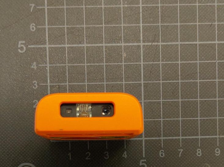
Workaround GmbH (ProGlove) External Photos Document MARK 3 Figure 1: Top View Figure 2: Bottom View Figure 3: Front View Workaround GmbH (ProGlove) Figure 4: Rear View Figure 5: Side View 1 Figure 6: Side View 2
ProGlove MARK 3 Label artwork
Workaround GmbH (ProGlove) 1 Internal Photos Document MARK 3 Figure 1: MARK 3 internal bottom view Figure 2: MARK 3 internal top view Workaround GmbH (ProGlove) 2 Figure 3: MARK 3 top en closure internal view Figure 4: MARK 3 bottom enclosure internal view Figure 5: Bottom View, Main PCB Figure 6: Top View,, Main PCB Antenna
RF Exposure Analysis FCC ID: 2AOJL-MARK3 Analysis for FCC portable use Standalone SAR test exclusion considerations are defined in KDB 447498D01 (v06) Chapter 4.3.1 where the 1-g head or body and 10-g extremity SAR exclusion threshold is defined by the following formula: [(max. power of channel, including tune-up tolerance, mW) / (min. test separation distance, mm)] * [√f(GHz)] ≤ 3.0 for 1-g SAR and ≤ 7.5 for 10-g extremity SAR •f(GHz) is the RF channel transmit frequency in GHz •Power and distance are rounded to the nearest mW and mm before calculation •The result is rounded to one decimal place for comparison For the LEO the maximum conducted output power is 0dBm (1.0mW). Applying the above data using the given KDB 447498 D01 formula, and minimum separation distance of 5mm, the following results: (1.0mW / 5 mm) x √2.4 GHz = 0.31 (i.e.: ≤ 3.0 for 1-g SAR and ≤ 7.5 for 10-g extremity SAR) This demonstrates the MARK 3 meets the criteria for 1-g head/ body and 10-g extremity SAR test exemption. Conclusion The MARK 3 can be used for Portable (or Mobile) usage. 15.09.2022 ____ ________________ Arif Çilg in Product Compliance Manager Workaround GmbH Workaround GmbH Rupert-Mayer-Straße 44 Building 64.08A 81379 Munich +49 (0)89 12085156 [email protected] www.proglove.com
IDVORSKY LABORATORIES Ltd. Belgrade Volgina 15, 11060 Belgrade, Serbia www.idvorsky.com [email protected] Phone: +381 11 6776329 This report is not valid unless signed/authorized and shall not be reproduced except in full Radio Spectrum Test Report #1344-4 Page 10 of 18 IDVORSKY LABORATORIES Ltd. Belgrade Volgina 15, 11060 Belgrade, Serbia www.idvorsky.com [email protected] Phone: +381 11 6776329 This report is not valid unless signed/authorized and shall not be reproduced except in full Radio Spectrum Test Report #1344-4 Page 11 of 18 IDVORSKY LABORATORIES Ltd. Belgrade Volgina 15, 11060 Belgrade, Serbia www.idvorsky.com [email protected] Phone: +381 11 6776329 This report is not valid unless signed/authorized and shall not be reproduced except in full Radio Spectrum Test Report #1344-4 Page 12 of 18 Test location: semi-anechoic chamber EUT to receiving antenna distance: 3 m EUT height: 1.5 m Azimuth during pre-scan: 0° (photos) Azimuth during radiation pattern measurement: 0 – 360° with 5° step Elevation angle: 0° (photo) – EUT is set in typical position for use, according to the manufacturer Receiving antenna polarization during pre-scan: VER and HOR (HOR is determined as the worst case for the measurements) Mode of operation: Normal modulation (continuous transmission) See clause 5.1.4 for the measurement details. IDVORSKY LABORATORIES Ltd. Belgrade Volgina 15, 11060 Belgrade, Serbia www.idvorsky.com [email protected] Phone: +381 11 6776329 This report is not valid unless signed/authorized and shall not be reproduced except in full Radio Spectrum Test Report #1344-4 Page 13 of 18 5.1.2. Results Graphical representation of the measurement results: Frequency [MHz] / Data rate Antenna radiation pattern, horizontal polarization 2402 / 1 Mbps 2440 / 1 Mbps IDVORSKY LABORATORIES Ltd. Belgrade Volgina 15, 11060 Belgrade, Serbia www.idvorsky.com [email protected] Phone: +381 11 6776329 This report is not valid unless signed/authorized and shall not be reproduced except in full Radio Spectrum Test Report #1344-4 Page 14 of 18 2480 / 1 Mbps 2402 / 2 Mbps IDVORSKY LABORATORIES Ltd. Belgrade Volgina 15, 11060 Belgrade, Serbia www.idvorsky.com [email protected] Phone: +381 11 6776329 This report is not valid unless signed/authorized and shall not be reproduced except in full Radio Spectrum Test Report #1344-4 Page 15 of 18 2440 / 2 Mbps 2480 / 2 Mbps IDVORSKY LABORATORIES Ltd. Belgrade Volgina 15, 11060 Belgrade, Serbia www.idvorsky.com [email protected] Phone: +381 11 6776329 This report is not valid unless signed/authorized and shall not be reproduced except in full Radio Spectrum Test Report #1344-4 Page 16 of 18 Maximum peak gain found: Frequency [MHz] / Data rate P R [dBm] (1) CL [dB] (2) AF [dB/m] (3) r[m] (4) Correction factor [dB] (5) P T [dBm] (6) Azimuth [°] Elevation angle [°] G T [dBi] (7) 2402 / 1 Mbps -50.03 3.01 31.25 3 11.77 0.15 327 0 -4.15 2440 / 1 Mbps -53.03 3.03 31.53 3 11.77 0.15 194 0 -6.85 2480 / 1 Mbps -55.74 3.06 31.96 3 11.77 0.15 205 0 -9.10 2402 / 2 Mbps -49.55 2.99 31.25 3 11.77 0.15 322 0 -3.70 2440 / 2 Mbps -51.71 3.03 31.53 3 11.77 0.15 329 0 -5.54 2480 / 2 Mbps -52.96 3.06 31.96 3 11.77 0.15 321 0 -6.32 (2) RF power measured on the receiver, without corrections (3) Cable losses (4) Receiving antenna factor (5) EUT to antenna distance (6) See 5.1.4. (7) Obtained values with the information that the maximum conducted RF output power is 0.15 dBm, according to the test report No. UL-RPT-RP-14317245-216-FCC issued on July 12, 2022 from UL INTERNATIONAL GERMANY GMBH. (8) [] = [ ] + 11.77 + [ ] − [ ] Maximum peak antenna gain is < 0 dBi (-3.70 dBi). 5.1.3. Deviations None. 5.1.4. Comments The test is performed with an unmodified sample, by radiated method. The test is performed in semi- anechoic chamber with absorbers on the floor. RF power ( [ ] ) was measured in the maximum radiation direction, with peak detector, at 3 m distance from EUT. The maximum peak gain was calculated using Friis transmission equation: [ ] = [ ] + [ ] + [ ] + 20 ! "#$ % (1) Antenna gain from antenna factor: = &.'( ! √ * (2) 20 + ) = 20 + 9.73 ) − 20 + . ) − 10 + ) (3) IDVORSKY LABORATORIES Ltd. Belgrade Volgina 15, 11060 Belgrade, Serbia www.idvorsky.com [email protected] Phone: +381 11 6776329 This report is not valid unless signed/authorized and shall not be reproduced except in full Radio Spectrum Test Report #1344-4 Page 17 of 18 [ ] = 19.76 − 20 + . ) − [ 012 ] (4) . = 3 4 = (∗ 6 4 = (∗ 7 4 [89:] (5) 20 + . ) = 20 3 4 % = 20 (∗ 7 4 [ 89: ] % = 20 + 300 ) − 20 ; [89:] = 49.54 − 20 ; [89:] (6) [ ] = 19.76 − +49.54 − 20 ; [89:] ) − [ 012 ] (7) [] = 20 ; [89:] − 29.78 − [ ] (8) Combining equations (1) and (8): [ ] = [ ] + [] + 20 ; [89:] − 29.78 − [ ] + 20 ! "#$ % (9) [ ] = [ ] + [] + 20 ; [89:] − 29.78 − [ ] + 20 + . ) − 20 + 4?@ ) (10) [ ] = [ ] + [] + 20 ; [89:] − 29.78 − [ + ) ] + 49.54 − 20 ; [89:] − 31.53 (11) [ ] = [ ] + [] − 11.77 − [ ] (12) [ ] + [] = [ ] + 11.77 + [ ] (13) (for matched antenna) Where: P T is the power fed into the transmitting (EUT’s) antenna input terminals G T – gain of transmitting antenna G R – gain of receiving antenna r – distance from EUT to receiving antenna, λ – wavelength AF – receiving antenna factor. Cable losses are also taken into account in the final calculation. IDVORSKY LABORATORIES Ltd. Belgrade Volgina 15, 11060 Belgrade, Serbia www.idvorsky.com [email protected] Phone: +381 11 6776329 This report is not valid unless signed/authorized and shall not be reproduced except in full Radio Spectrum Test Report #1344-4 Page 18 of 18 6. MEASUREMENT EQUIPMENT The following equipment is used for tes…
Text truncated - open the document above for the full version.
Product Equality Declaration 12.12.2022 Subject: LEO and MARK 3 Equality FCC Number LEO: 2AOJL-LEO IC Number LEO: 23450-LEO FCC Number MARK 3: 2AOJL-MARK-3 IC Number: 23450-MARK3 To whom i t may concern We, Workaround GmbH hereby state that the our model LEO and MARK 3 is in the same base for their design and the only main difference is the scan engine. Please see below the list of the same main critical components: RF Component: Nordic nRF 5340 Antenna: The same custom design antenna (PCB, IoT Platform BLE Antenna) Main PCB: the same custom design Battery: The same (ATL 692532) Difference: Scan engine MARK 3: Zebra SE 5500 Scan engine LEO: Zebra SE 4107 According to this equality we here by declare that the LEO models FCC or ISED test reports and results can be us ed or transferred for MARK 3 FCC and ISED certification. report numbers of LEO (FCC: UL-RPT-RP-14317245-216-FCC / ISED Canada: UL-RPT- RP-14317245-216-ISED) from which the results can be transferred verification testing has been performed with MARK 3 with references to the reports (FCC: UL-RPT- RP-14421035-216-FCC / ISED Canada: UL-RPT-RP-14421035-216-ISED). Yours faithfully, Arif Cilgin Product Compliance Manager Workaround GmbH Rupert-Mayer-Straße 44 Building 64.08A 81379 Munich +49 (0)89 12085156 [email protected] www.proglove.com
UL INTERNATIONAL GERMANY GMBH Hedelfinger Str. 61 70327 Stuttgart, Germany [email protected] TEST REPORT Test Report No. : UL-RPT-RP-14317245-216-FCC Applicant : Workaround GmbH Model No. : LEO FCC ID : 2AOJL-LEO Technology : Bluetooth – Low Energy Test Standard(s) : FCC Parts 15.207, 15.209(a) & 15.247 For details of applied tests refer to test result summary 1. This test report shall not be reproduced in full or partial, without the written approval of UL International Germany GmbH. 2. The results in this report apply only to the sample tested. 3. The test results in this report are traceable to the national or international standards. 4. Test Report Version 1.0 5. Result of the tested sample: PASS _________________________ ___________________________ Prepared by: Sercan Usta Approved by: Rachid, Acharkaoui Title: Laboratory Engineer Title: Laboratory Manager Date: 12 July 2022 Date: 12 July 2022 This laboratory is accredited by DAkkS. The tests reported herein have been performed in accordance with its’ terms of accreditation. UL INTERNATIONAL GERMANY GMBH TEST REPORT NO: UL-RPT-RP-14317245-216-FCC TEST REPORT VERSION 1.0 ISSUE DATE: 12 JULY 2022 Page 2 of 49 FCC 15.247 BT LE - Template Vers. 1.4 UL INTERNATIONAL GERMANY GMBH TEST REPORT NO: UL-RPT-RP-14317245-216-FCC TEST REPORT VERSION 1.0 ISSUE DATE: 12 JULY 2022 Page 3 of 49 FCC 15.247 BT LE - Template Vers. 1.4 This page has been left intentionally blank. UL INTERNATIONAL GERMANY GMBH TEST REPORT NO: UL-RPT-RP-14317245-216-FCC TEST REPORT VERSION 1.0 ISSUE DATE: 12 JULY 2022 Page 4 of 49 FCC 15.247 BT LE - Template Vers. 1.4 Table of Contents 1. Customer Information .............................................................................................................. 5 1.1. Applicant Information 5 1.2. Manufacturer Information 5 2. Summary of Testing ................................................................................................................. 6 2.1. General Information 6 Applied Standards 6 Location 6 Date information 6 2.2. Summary of Test Results 7 2.3. Methods and Procedures 7 2.4. Deviations from the Test Specification 7 3. Equipment Under Test (EUT) .................................................................................................. 8 3.1. Identification of Equipment Under Test (EUT) 8 3.2. Description of EUT 8 3.3. Modifications Incorporated in the EUT 8 3.4. Additional Information Related to Testing 9 3.5. Support Equipment 9 A. Support Equipment (In-house) 9 B. Support Equipment (Manufacturer supplied) 9 4. Operation and Monitoring of the EUT during Testing ......................................................... 10 4.1. Operating Modes 10 4.2. Configuration and Peripherals 11 5. Measurements, Examinations and Derived Results ............................................................ 12 5.1. General Comments 12 5.2. Test Results 13 5.2.1. Transmitter AC Conducted Spurious Emissions 13 5.2.2. Transmitter 6 dB Bandwidth 19 5.2.3. Transmitter Duty Cycle 22 5.2.4. Transmitter Maximum Peak Output Power 25 5.2.5. Transmitter Radiated Emissions 30 5.2.6. Transmitter Band Edge Radiated Emissions 41 6. Measurement Uncertainty ..................................................................................................... 47 7. Used equipment ..................................................................................................................... 48 8. Report Revision History ........................................................................................................ 49 UL INTERNATIONAL GERMANY GMBH TEST REPORT NO: UL-RPT-RP-14317245-216-FCC TEST REPORT VERSION 1.0 ISSUE DATE: 12 JULY 2022 Page 5 of 49 FCC 15.247 BT LE - Template Vers. 1.4 1. Customer Information 1.1.Applicant Information Company Name: Workaround GmbH Company Address: Rupert-Mayer-Str. 44, 81379 Munich,Germany Company Phone No.: +49 89 26203500 Company E-Mail: [email protected] Contact Person: Arif Şamil Çılgın Contact E-Mail Address: [email protected] Contact Phone No.: +4917677379345 1.2.Manufacturer Information Company Name: Workaround GmbH Company Address: Rupert-Mayer-Str. 44, 81379 Munich,Germany Company Phone No.: +49 89 26203500 Company E-Mail: [email protected] Contact Person: Arif Şamil Çılgın Contact E-Mail Address: [email protected] Contact Phone No.: +4917677379345 UL INTERNATIONAL GERMANY GMBH TEST REPORT NO: UL-RPT-RP-14317245-216-FCC TEST REPORT VERSION 1.0 ISSUE DATE: 12 JULY 2022 Page 6 of 49 FCC 15.247 BT LE - Template Vers. 1.4 2. Summary of Testing 2.1. General Information Applied Standards Specification Reference: 47CFR15.247 Specification Title: Code of Federal Regulations Volume 47 (Telecommunications): Part 15 Subpart C (Intentional Radiators) - Section 15.247 Specification Reference: 47CFR15.207 and 47CFR15.209 Specification Title: Code of Federal Regulations Volume 47 (Telecommunications): Part 15 Subpart C (Intentional Radiators) - Sections 15.207 and 15.209 Location Location of Testing: UL International Germany GmbH Hedelfinger Str. 61 70327 Stuttgart Germany Test Firm Registration: 399704 Date information Order Date: 06 May 2022 EUT arrived: 18 May 2022 Test Dates: 07 June 2022 – 22 June 2022 EUT returned: -/- UL INTERNATIONAL GERMANY GMBH TEST REPORT NO: UL-RPT-RP-14317245-216-FCC TEST REPORT VERSION 1.0 ISSUE DATE: 12 JULY 2022 Page 7 of 49 FCC 15.247 BT LE - Template Vers. 1.4 2.2. Summary of Test Results Clause Measurement Complied Did not comply Not performed Not applicable Part 15.207 Transmitter AC Conducted Emissions ☒ ☐ ☐ ☐ Part 15.247(a)(2) Transmitter Minimum 6 dB Bandwidth ☒ ☐ ☐ ☐ Part 15.35(c) Transmitter Duty Cycle (1) ☒ ☐ ☐ ☐ Part 15.247(e) Transmitter Power Spectral Density (2) ☐ ☐ ☒ ☐ Part 15.247(b)(3) Transmitter Maximum Peak Output Power ☒ ☐ ☐ ☐ Part 15.247(d)/15.209(a) Transmitter Radiated Emissions ☒ ☐ ☐ ☐ Part 15.247(d)/15.209(a) Transmitter Band Edge Radiated Emissions ☒ ☐ ☐ ☐ Note(s): 1. The measurement was performed to…
Text truncated - open the document above for the full version.
UL INTERNATIONAL GERMANY GMBH Hedelfinger Str. 61 70327 Stuttgart, Germany [email protected] TEST REPORT Test Report No. : UL-RPT-RP-14421035-216-FCC Applicant : Workaround GmbH Model No. : MARK 3 FCC ID : 2AOJL- MARK-3 Technology : Bluetooth – Low Energy Test Standard(s) : FCC Parts 15.209(a) & 15.247 For details of applied tests refer to test result summary 1. This test report shall not be reproduced in full or partial, without the written approval of UL International Germany GmbH. 2. The results in this report apply only to the sample tested. 3. The test results in this report are traceable to the national or international standards. 4. Test Report Version 1.0 5. Result of the tested sample: PASS _________________________ ___________________________ Prepared by: Sercan Usta Approved by: Rac…
Text truncated - open the document above for the full version.
| # | Rule Parts | Frequency Range | Power Output |
|---|---|---|---|
| 1 | 15C | 2.40 GHz - 2.48 GHz | 1.00 mW |
ProGlove MARK Display Scanner
Equipment Class
DTS - Digital Transmission System