2AOK9-X800Dash Cam
70mai Co.,Ltd.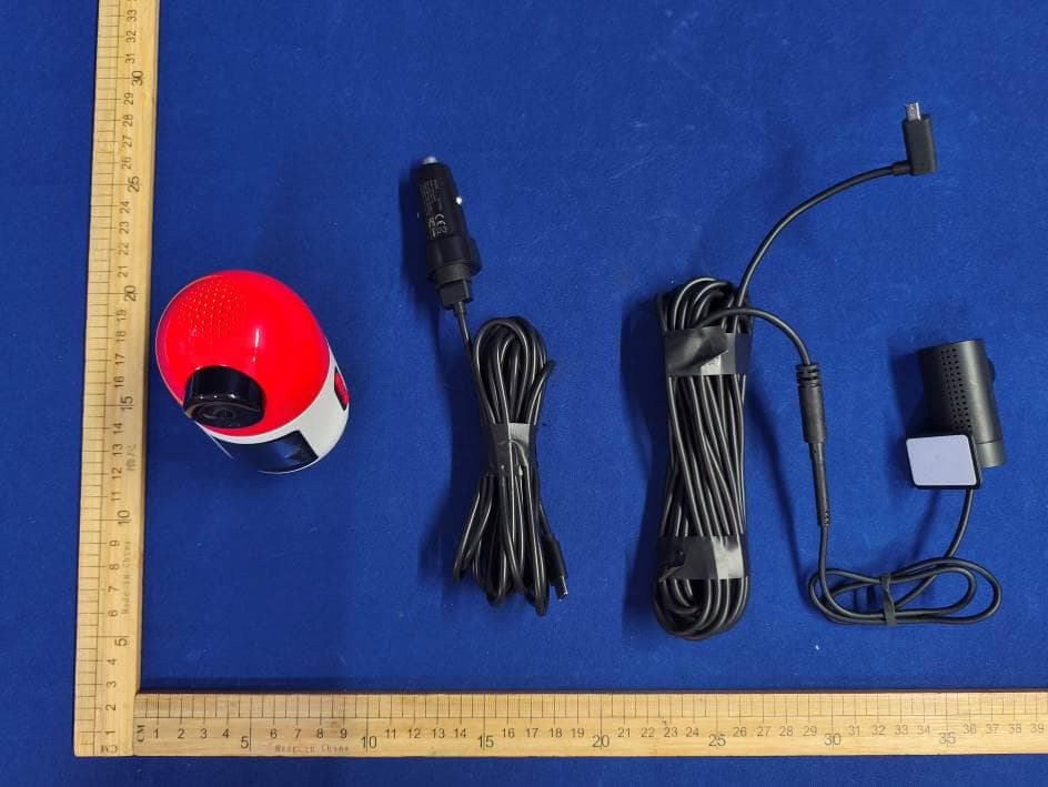
Click to zoom
Application Details
- Equipment Class
- NII - Unlicensed National Information Infrastructure TX
- Date of Grant
- Oct 10, 2024
- Application Purpose
- Original Equipment
- Date of Application
- Oct 10, 2024
- Equipment Note
- Dash Cam
- Frequency Range
- 5745.00000000 - 5825.00000000
- Company
- 70mai Co.,Ltd.
- Country
- China
Documents & Files
Document Text
Text extracted from the exhibit documents filed with the FCC. Open a document above to read the original.
Users Manual
70mai Dash Cam 4K Omni User Manual View the User guide for product functions and FAQs. Scan the QR code and email us at [email protected] 01 Product overview Please read this manual carefully before using the product and keep it in a safe place. Note: Illustrations of the product, accessories, and user interface in the user manual are for reference purposes only. The actual product and functions may vary due to product enhancements. 1. Dash Cam × 1 2. Power cord × 1 3. Car charger × 1 4. Mount (pre-installed on the dash cam) × 1 Package contents Dash cam 5. Adhesive sticker × 1 6. Electrostatic sticker × 2 7. Wiring trim tool × 1 8. User manual × 1 ①. Microphone ②. Rear camera port ③. Power port ④. Memory card slot ⑤. Display screen ⑥. Round-shape indicator ⑦. Rotating lens ⑧. Camera ⑨. Ventilation holes ⑩. Adhesive sticker ⑪. Mount ⑫. Power button ⑬. Up button ⑭. Down button ⑮. Speaker 02 Installation 1. Selecting mounting position Mount the dash cam on either of the recommended positions of the front windshield as appropriate: ① . Near the center of rearview mirror; ② . On the front of the passenger seat. Note: Make sure the camera is below the level line of the rearview mirror. 3. Installing the memory card Open the cover of the memory card slot. Insert the memory card into the slot, with its contacts side facing away from the display screen. And then close the cover. 2. Installing the electrostatic sticker Paste the electrostatic sticker on the selected position, with the gap image facing upwards. Press the sticker to remove air bubbles out. Avoid the edge of the windshield and select the flat and smooth area for the installation. Note: Keep windshield clean and dry without liquid residue to prevent the sticker from losing adhesion and dash cam from dropping. 03 4. Installing the dash cam Paste the dash cam on the electrostatic sticker. Make sure the gap on the adhesive sticker aligns with that on the electrostatic sticker, and the display screen faces the vehicle interior. 5. Connecting the power cord Connect the dash cam and car charger with the power cord. 6. Routing cable Route the power cord to the vehicle’s power outlet and plug the car charger into the power outlet. Start the car engine, and the dash cam will automatically turn on. Notes: • Use the included wiring trim tool to hide the power cord underneath the vehicle’s headliner and rubber seal along the A-pillar. • Depending on the vehicle, the power outlet may be located in a different position. The provided figure is for reference only. 04 Installing the mount Installing/uninstalling the mount Uninstalling the mount 7. Adjusting the dash cam angle Adjust the dash cam angle based on the preview screen. Mount Microphone Dash cam Hold the dash cam and screw it clockwise , and then the dash cam will separate with the mount. 1. Align the microphone with the icon on the mount, and the dash cam is inserted to the mount. 2. Hold the dash cam and screw counterclockwise until the microphone is aligned with the icon on the mount, and then the dash cam is tightened up with the mount. 05 Connecting with the 70mai app This product needs to be used in conjunction with the 70mai app. Follow the steps below to connect it with the app. 1. Scan the QR code to download and install the app. Or search for “70mai” in the app store to download and install it. 2. Open the app, tap "+" in the device page, find the corresponding dash cam type and tap the dash cam image. 3. Turn on the dash cam and enable the Wi-Fi hotspot. Follow the on-screen instructions to confirm the authorization. And then the dash cam is added. 4. Go back to the 70mai app. In the device page, connect the dash cam Wi-Fi hotspot and enter the dash cam's homepage. You can view the live video and configure the dash cam settings. Scan to download the app Notes: • For some dash cam models, the Wi-Fi hotspot is enabled by default. • Android 5.0 & iOS 11.0 or above is required to connect to the dash cam’s Wi-Fi hotspot with a mobile phone. As mobile phone operating systems continue to be updated, the minimum requirements for Android and iOS systems may also increase. If you need more help when connecting the app, please scan the QR code below to view the tutorial video. Scan to view the video 06 Button functions Button typeOperationFunction Power button Press once when the dash cam is turned off. Note: The dash cam should be connected with external power source. Turn on the device. Press once on the quick control panel or menu page.Confirm your selection. Press twice on the home page.Record an emergency video. Press and hold for about 3 seconds.Turn off the device. Press and hold for about 15 seconds.Force shutdown the device. Up buttonPress once on the home page.Go to the end of the quick control panel. Down buttonPress once on the home page.Go to the start of the quick control panel The rear recording function of this product needs to be used with a rear camera. Scan the QR code to obtain the user guide for the rear camera. Note: To avoid the rear camera malfunction due to device incompatibility, it is recommended to use a rear camera from 70mai brand. Accessories (optional) 07 Control your dash cam with voice commands. The supported languages are English, Italian, Japanese and Mandarin (when the dash cam’s broadcast language is Traditional Chinese). The voice commands are as follows: Voice command Function Take photoDash cam will take a photo. Record videoDash cam will record an emergency video. Record audioDash cam will record audio and video. Turn off audio Dash cam will not record audio but only video. Enable hotspotDash cam's Wi-Fi hotspot will turn on. Disable hotspotDash cam's Wi-Fi hotspot will turn off. Switch front view¹ The real-time image on the home page will switch to front view. Switch rear view¹ The real-time image on the home page will switch to rear view. Capture left The rotating lens will rotate to the preset fixed angle on the left and continue to record. Capture …
Text truncated - open the document above for the full version.
Attestation Statements
Rev 1/26/2023 70mai Co.,Ltd. Federal Communications Commission Authorization and Evaluation Division 7435 Oakland Mills Road Columbia, MD 21046 USA Date: 09-30-2024 Ref: Attestation Statements Part 2.911(d)(5)(i) Filing FCC ID: 2AOK9-X800 [70mai Co.,Ltd.] (“the applicant”) certifies that the equipment for which authorization is sought is not “covered” equipment prohibited from receiving an equipment authorization pursuant to section 2.903 of the FCC rules. Sincerely, (Applicant signature) (Applicant printed name) Cindy Lv Rev 1/26/2023 70mai Co.,Ltd. Federal Communications Commission Authorization and Evaluation Division 7435 Oakland Mills Road Columbia, MD 21046 USA Date: 09-30-2024 Ref: Attestation Statements Part 2.911(d)(5)(ii) Filing FCC ID: 2AOK9-X800 [70mai Co.,Ltd.] (“the applicant”) certifies that, as of the date of the filing of the application, the applicant is not identified on the Covered List (as a specifically named entity or any of its subsidiaries or affiliates) as an entity producing “covered” equipment. Sincerely, (Applicant signature) (Applicant printed name) Cindy Lv
Internal Photos
2.4G/5G WiFi antenna BLE antenna
RF Exposure Info
FCC ID : 2AOK9-X800 RF EXPOSURE EVALUATION According to FCC 1.1310: The criteria listed in the following table shall be used to evaluate the environment impact of human exposure to radio frequency (RF) Radiation as specified in §1.1307(b) Limits for Maximum Permissible Exposure (MPE) Frequency Range(MHz) Electric Field Strength(V/m) Magnetic Field Strength(A/m) Power Density(mW/cm 2 ) Average Time (A) Limits for Occupational/Control Exposures 300-1500 -- -- F/300 6 1500- 100000 -- -- 5 6 (B) Limits for General Population/Uncontrol Exposures 300-1500 -- -- F/1500 6 1500- 100000 -- -- 1 30 11.1 Friis transmission formula: Pd= (Pout*G)\ (4*pi*R 2 ) Where Pd= Power density in mW/cm 2 Pout=output power to antenna in mW G= Numeric gain of the antenna relative to isotropic antenna Pi=3.1416 R= distance between observation point and center of the radiator in cm Pd the limit of MPE, 1mW/cm 2 ,If we know the maximum gain of the nd total power input to the antenna, through the calculation, we will know the distance where the MPE limit is reached. RF Exposure Information: The radiated output power of this device meets the limits of FCC/IC radio frequency exposure limits.This device should be operated with a minimum separation distance of 20cm (8 inches) between the equipment and a person's body. 11.2 Measurement Result BLE Antenna gain: 0.04 dBi Measured power (dBm) Tune-up power (dBm) Max tune-up power (dBm) Antenna Gain Numeric Evaluation result (mW/cm2 ) Power density Limits (mW/cm2 ) -18.87 -20.0 to -18.0 -18.0 1.01 0.000003 1 Wifi 2.4G Antenna gain: 2.23 dBi Measured power (dBm) Tune-up power (dBm) Max tune-up power (dBm) Antenna Gain Numeric Evaluation result (mW/cm2 ) Power density Limits (mW/cm2 ) 23.63 22.0 to 24.0 24.0 1.67 0.08351 1 Wifi 5G Antenna gain: 3.12 dBi Frequency band Measure d power (dBm) Tune-up power (dBm) Max tune- up power (dBm) Antenna Gain Numeric Evaluation result (mW/cm2 ) Power density Limits (mW/cm2 ) 5150MHz- 5250MHz 15.08 14.0 to 16.0 16.0 2.05 0.01625 1 5725MHz- 5850MHz 15.36 14.0 to 16.0 16.0 2.05 0.01625 1
Test Report
Report No. ENS2407220144W00903R Page 1 of 112 Ver.1.0 TEST REPORT Product Name : Dash Cam Model Number : X800, X800-2 FCC ID : 2AOK9-X800 Prepared for : 70mai Co.,Ltd Address : Room2220,building2,No.588,Zixingroad,MinHangDistrict,S hanghai.CHINA Prepared by : EMTEK (SHENZHEN) CO., LTD. Address : Bldg 69, Majialong Industry Zone, Nanshan District, Shenzhen, Guangdong, China Tel: (0755) 26954280 Fax: (0755) 26954282 Report Number : ENS2407220144W00903R Date(s) of Tests : August 24, 2024 to September 10, 2024 Date of issue : September 11, 2024 $二维码$ Report No. ENS2407220144W00903R Page 2 of 112 Ver.1.0 TABLE OF CONTENTS 1 TEST RESULT CERTIFICATION ....................................................................................................... 4 2 EUT TECHNICAL DESCRIPTION ..................................................................................................... 5 3 SUMMARY OF TEST RESULT .......................................................................................................... 7 4 TEST METHODOLOGY ..................................................................................................................... 8 4.1 GENERAL DESCRIPTION OF APPLIED STANDARDS ............................................................. 8 4.2 MEASUREMENT EQUIPMENT USED ....................................................................................... 8 4.3 DESCRIPTION OF TEST MODES .............................................................................................. 9 5 FACILITIES AND ACCREDITATIONS ............................................................................................. 11 5.1 FACILITIES ............................................................................................................................... 11 5.2 LABORATORY ACCREDITATIONS AND LISTINGS ................................................................ 11 6 TEST SYSTEM UNCERTAINTY ...................................................................................................... 12 7 SETUP OF EQUIPMENT UNDER TEST ......................................................................................... 13 7.1 RADIO FREQUENCY TEST SETUP ......................................................................................... 13 7.2 RADIO FREQUENCY TEST SETUP ......................................................................................... 13 7.3 CONDUCTED EMISSION TEST SETUP .................................................................................. 15 7.4 BLOCK DIAGRAM CONFIGURATION OF TEST SYSTEM ...................................................... 16 7.5 SUPPORT EQUIPMENT ........................................................................................................... 16 8 TEST REQUIREMENTS................................................................................................................... 17 8.1 BANDWIDTH MEASUREMENT ............................................................................................... 17 8.2 MAXIMUM CONDUCTED OUTPUT POWER ........................................................................... 57 8.3 MAXIMUM PEAK POWER DENSITY ....................................................................................... 73 8.4 UNDESIRABLE RADIATED SPURIOUS EMISSION ................................................................ 90 8.5 POWER LINE CONDUCTED EMISSIONS ............................................................................. 109 8.6 ANTENNA APPLICATION ....................................................................................................... 110 Report No. ENS2407220144W00903R Page 3 of 112 Ver.1.0 Modified Information Version Report No. Revision Date Summary Ver.1.0 ENS2407220144W00903R / Original Report Report No. ENS2407220144W00903R Page 4 of 112 Ver.1.0 1 TEST RESULT CERTIFICATION Applicant : 70mai Co.,Ltd Address: Room2220,building2,No.588,Zixingroad,MinHangDistrict,Shanghai.CHINA Manufacturer : 70mai Co.,Ltd Address: Room2220,building2,No.588,Zixingroad,MinHangDistrict,Shanghai.CHINA EUT : Dash Cam Model Name : X800, X800-2 Trademark : N/A Measurement Procedure Used: APPLICABLE STANDARDS STANDARD TEST RESULT FCC 47 CFR Part 2, Subpart J FCC 47 CFR Part 15, Subpart E PASS The above equipment was tested by EMTEK (SHENZHEN) CO., LTD. The test data, data evaluation, test procedures, and equipment configurations shown in this report were made in accordance with the procedures given in ANSI C63.10 (2013) and the energy emitted by the sample EUT tested as described in this report is in compliance with the above table standards requirement. The test results of this report relate only to the tested sample identified in this report. Date of Test : August 24, 2024 to September 10, 2024 Prepared by : Una Yu/Editor Reviewer : Joe Xia/Supervisor Approved & Authorized Signer : Lisa Wang/Manager Report No. ENS2407220144W00903R Page 5 of 112 Ver.1.0 2 EUT TECHNICAL DESCRIPTION Characteristics Description Product Dash Cam Model Number X800, X800-2 Wifi Type UNII-1: 5150MHz-5250MHz Band UNII-3: 5725MHz-5850MHz Band WLAN Supported 802.11a 802.11n(20MHz channel bandwidth) 802.11n(40MHz channel bandwidth) 802.11ac(20MHz channel bandwidth) 802.11ac(40MHz channel bandwidth) 802.11ac(80MHz channel bandwidth) 802.11ax(20MHz channel bandwidth) 802.11ax(40MHz channel bandwidth) 802.11ax(80MHz channel bandwidth) Modulation OFDM with BPSK/QPSK/16QAM/64QAM for 802.11a/n OFDM with BPSK/QPSK/16QAM/64QAM/256QAM/1024QAM for 802.11ac/ax Frequency Range 5150MHz-5250MHz Band 5180-5240MHz for 802.11a 5180-5240MHz for 802.11n(HT20) 5190-5230MHz for 802.11n(HT40) 5180-5240MHz for 802.11ac(HT20) 5190-5230MHz for 802.11ac(HT40) 5210MHz for 802.11ac(HT80) 5180-5240MHz for 802.11ax(HE20) 5190-5230MHz for 802.11ax(HE40) 5210MHz for 802.11ax(HE80) 5725MHz-5850MHz Band 5745-5825MHz for 802.11a 5745-5825MHz for 802.11n(HT20) 5755-5795MHz for 802.11n(HT40) 5745-5825MHz for 802.11ac(HT20) 5755-5795MHz for 802.11ac…
Text truncated - open the document above for the full version.
Test Report
Report No. ENS2407220144W00903R Page 49 of 112 Ver.1.0 Min emission bandwidth (6db) TestMode Antenna Freq(MHz) 6db EBW [MHz] FL[MHz] FH[MHz] Limit[MHz] Verdict 11A Ant1 5745 16.28 5736.84 5753.12 0.5 PASS 5785 16.28 5776.84 5793.12 0.5 PASS 5825 16.28 5816.84 5833.12 0.5 PASS 11N20SISO Ant1 5745 17.16 5736.24 5753.40 0.5 PASS 5785 17.32 5776.44 5793.76 0.5 PASS 5825 16.92 5816.48 5833.40 0.5 PASS 11N40SISO Ant1 5755 35.44 5737.24 5772.68 0.5 PASS 5795 35.92 5777.24 5813.16 0.5 PASS 11AC20SISO Ant1 5745 17.56 5736.20 5753.76 0.5 PASS 5785 16.92 5776.48 5793.40 0.5 PASS 5825 16.84 5816.56 5833.40 0.5 PASS 11AC40SISO Ant1 5755 36.08 5736.84 5772.92 0.5 PASS 5795 36.08 5776.84 5812.92 0.5 PASS 11AC80SISO Ant1 5775 75.52 5737.24 5812.76 0.5 PASS 11AX20SISO Ant1 5745 18.36 5735.60 5753.96 0.5 PASS 5785 18.32 5775.92 5794.24 0.5 PASS 5825 18.28 5815.96 5834.24 0.5 PASS 11AX40SISO Ant1 5755 37.60 5736.20 5773.80 0.5 PASS 5795 37.60 5776.20 5813.80 0.5 PASS 11AX80SISO Ant1 5775 76.64 5736.44 5813.08 0.5 PASS Report No. ENS2407220144W00903R Page 50 of 112 Ver.1.0 11A_Ant1_5745 11A_Ant1_5785 11A_Ant1_5825 Report No. ENS2407220144W00903R Page 51 of 112 Ver.1.0 11N20SISO_Ant1_5745 11N20SISO_Ant1_5785 11N20SISO_Ant1_5825 Report No. ENS2407220144W00903R Page 52 of 112 Ver.1.0 11N40SISO_Ant1_5755 11N40SISO_Ant1_5795 Report No. ENS2407220144W00903R Page 53 of 112 Ver.1.0 11AC20SISO_Ant1_5745 11AC20SISO_Ant1_5785 11AC20SISO_Ant1_5825 11AC40SISO_Ant1_5755 Report No. ENS2407220144W00903R Page 54 of 112 Ver.1.0 11AC40SISO_Ant1_5795 11AC80SISO_Ant1_5775 11AX20SISO_Ant1_5745 Report No. ENS2407220144W00903R Page 55 of 112 Ver.1.0 11AX20SISO_Ant1_5785 11AX20SISO_Ant1_5825 11AX40SISO_Ant1_5755 Report No. ENS2407220144W00903R Page 56 of 112 Ver.1.0 11AX40SISO_Ant1_5795 11AX80SISO_Ant1_5775 Report No. ENS2407220144W00903R Page 57 of 112 Ver.1.0 8.2 MAXIMUM CONDUCTED OUTPUT POWER 8.2.1 Applicable Standard According to FCC Part 15.407(a)(1) for UNII Band I According to FCC Part 15.407(a)(2) for UNII Band II-A and UNII Band II-C According to FCC Part 15.407(a)(3) for UNII Band III According to 789033 D02 Section II(E) 8.2.2 Conformance Limit For the band 5.15-5.25 GHz, (a) (1) (i) For an outdoor access point operating in the band 5.15-5.25 GHz, the maximum conducted output power over the frequency band of operation shall not exceed 1 W provided the maximum antenna gain does not exceed 6 dBi. If transmitting antennas of directional gain greater than 6 dBi are used, both the maximum conducted output power and the maximum power spectral density shall be reduced by the amount in dB that the directional gain of the antenna exceeds 6 dBi. The maximum e.i.r.p. at any elevation angle above 30 degrees as measured from the horizon must not exceed 125 mW (21 dBm). (a) (1) (ii) For an indoor access point operating in the band 5.15-5.25 GHz, the maximum conducted output power over the frequency band of operation shall not exceed 1 W provided the maximum antenna gain does not exceed 6 dBi. If transmitting antennas of directional gain greater than 6 dBi are used, both the maximum conducted output power and the maximum power spectral density shall be reduced by the amount in dB that the directional gain of the antenna exceeds 6 dBi. (a) (1) (iii) For fixed point-to-point access points operating in the band 5.15-5.25 GHz, the maximum conducted output power over the frequency band of operation shall not exceed 1 W. Fixed point-to-point U-NII devices may employ antennas with directional gain up to 23 dBi without any corresponding reduction in the maximum conducted output power or maximum power spectral density. For fixed point-to-point transmitters that employ a directional antenna gain greater than 23 dBi, a 1 dB reduction in maximum conducted output power and maximum power spectral density is required for each 1 dB of antenna gain in excess of 23 dBi. Fixed, point-to-point operations exclude the use of point-to-multipoint systems, omnidirectional applications, and multiple collocated transmitters transmitting the same information. The operator of the U-NII device, or if the equipment is professionally installed, the installer, is responsible for ensuring that systems employing high gain directional antennas are used exclusively for fixed, point-to-point operations. (a) (1) (iv) For mobile and portable client devices in the 5.15-5.25 GHz band, the maximum conducted output power over the frequency band of operation shall not exceed 250 mW provided the maximum antenna gain does not exceed 6 dBi. If transmitting antennas of directional gain greater than 6 dBi are used, both the maximum conducted output power and the maximum power spectral density shall be reduced by the amount in dB that the directional gain of the antenna exceeds 6 dBi. For the 5.25-5.35 GHz and 5.47-5.725 GHz bands (a) (2) the maximum conducted output power over the frequency bands of operation shall not exceed the lesser of 250 mW or 11 dBm + 10 log B, where B is the 26 dB emission bandwidth in megahertz. In addition, the maximum power spectral density shall not exceed 11 dBm in any 1 megahertz band. If transmitting antennas of directional gain greater than 6 dBi are used, both the maximum conducted output power and the maximum power spectral density shall be reduced by the amount in dB that the directional gain of the antenna exceeds 6 dBi. For the band 5.725-5.85 GHz (a) (3)For the band 5.725-5.85 GHz, the maximum conducted output power over the frequency band of operation shall not exceed 1 W. In addition, the maximum power spectral density shall not exceed 30 dBm in any 500-kHz band. If transmitting antennas of directional gain greater than 6 dBi are used, both the maximum conducted output power and the maximum power spectral density shall be reduced by the amount in dB that the directional gain of the antenna exceeds 6 dBi. 8.2.3 Test Configuration Test according to clause 6.1 radio frequency test setup 1. Report No. ENS2407220144W00903R Page 58 of 112 Ver.1…
Text truncated - open the document above for the full version.
Test Report
Report No. ENS2407220144W00903R Page 93 of 112 Ver.1.0 For Undesirable radiated Spurious Emission in U-NII – 1 Undesirable radiated Spurious Emission Above 1GHz (1GHz to 40GHz) All of the configurations or modes are tested, the data of the worst case is recorded in the report. Highest gain of each antenna and highest output power is ANT3 and MIMO as below: Test mode: 802.11a(20) Frequency(MHz): 5180 Freq. (MHz) Ant.Pol. Field Strength (dBuV/m) E.I.R.P (dBm) Limit (dBm) Over(dB) H/V 8687.84 V 64.79 -30.44 -27 3.44 11783.3 V 66.74 -28.49 -27 1.49 17897.9 V 67.79 -27.44 -27 0.44 7335.66 H 60.83 -34.4 -27 7.4 9801.90 H 66.40 -28.83 -27 1.83 17685.3 H 67.87 -27.36 -27 0.36 Test mode: 802.11a(20) Frequency(MHz): 5200 Freq. (MHz) Ant.Pol. Field Strength (dBuV/m) E.I.R.P (dBm) Limit (dBm) Over(dB) H/V 7990.49 V 63.49 -31.74 -27 4.74 9708.35 V 66.12 -29.11 -27 2.11 17727.8 V 67.60 -27.63 -27 0.63 8407.20 H 63.81 -31.42 -27 4.42 9657.32 H 65.42 -29.81 -27 2.81 15159.5 H 67.63 -27.6 -27 0.6 Test mode: 802.11a(20) Frequency(MHz): 5240 Freq. (MHz) Ant.Pol. Field Strength (dBuV/m) E.I.R.P (dBm) Limit (dBm) Over(dB) H/V 9002.50 V 65.00 -30.23 -27 3.23 11953.47 V 66.27 -28.96 -27 1.96 17838.4 V 67.00 -28.23 -27 1.23 9002.50 H 65.40 -29.83 -27 2.83 12659.3 H 66.79 -28.44 -27 1.44 17778.8 H 67.38 -27.85 -27 0.85 Report No. ENS2407220144W00903R Page 94 of 112 Ver.1.0 Test mode: 802.11a(20) Frequency(MHz): 5180 Freq. (MHz) Ant.Pol. Emission Level(dBuV/m) Limit 3m(dBuV/m) Over(dB) Detector 8687.84 V 64.79 74.00 9.21 peak 11783.3 V 66.74 74.00 7.26 peak 17897.9 V 67.79 74.00 6.21 peak 8687.843 V 46.57 54.00 7.43 AVG 11783.39 V 45.83 54.00 8.17 AVG 17897.94 V 46.96 54.00 7.04 AVG 7335.66 H 60.83 74.00 13.17 peak 9801.90 H 66.40 74.00 7.60 peak 17685.3 H 67.87 74.00 6.13 peak 7335.667 H 41.68 54.00 12.32 AVG 9801.901 H 43.03 54.00 10.97 AVG 17685.34 H 47.37 54.00 6.63 AVG Test mode: 802.11a(20) Frequency(MHz): 5200 Freq. (MHz) Ant.Pol. Emission Level(dBuV/m) Limit 3m(dBuV/m) Over(dB) Detector 7990.49 V 63.49 74.00 10.51 peak 9708.35 V 66.12 74.00 7.88 peak 17727.8 V 67.60 74.00 6.40 peak 7990.495 V 43.45 54.00 10.55 AVG 9708.354 V 43.26 54.00 10.74 AVG 17727.86 V 47.32 54.00 6.68 AVG 8407.20 H 63.81 74.00 10.19 peak 9657.32 H 65.42 74.00 8.58 peak 15159.5 H 67.63 74.00 6.37 peak 8407.203 H 44.53 54.00 9.47 AVG 9657.328 H 42.90 54.00 11.10 AVG 15159.57 H 44.12 54.00 9.88 AVG Test mode: 802.11a(20) Frequency(MHz): 5240 Freq. (MHz) Ant.Pol. Emission Level(dBuV/m) Limit 3m(dBuV/m) Over(dB) Detector 9002.50 V 65.00 74.00 9.00 peak 11953.4 V 66.27 74.00 7.73 peak 17838.4 V 67.00 74.00 7.00 peak 9002.501 V 47.45 54.00 6.55 AVG 11953.47 V 45.77 54.00 8.23 AVG 17838.41 V 47.43 54.00 6.57 AVG 9002.50 H 65.40 74.00 8.60 peak 12659.3 H 66.79 74.00 7.21 peak 17778.8 H 67.38 74.00 6.62 peak 9002.501 H 47.44 54.00 6.56 AVG 12659.32 H 47.71 54.00 6.29 AVG 17778.88 H 47.37 54.00 6.63 AVG Note: (1) All Readings are Peak Value (VBW=3MHz) and Peak Value (VBW=10Hz). (2) Emission Level= Reading Level+Correct Factor +Cable Loss. (3) Correct Factor= Ant_F + Cab_L - Preamp (4) The reading of emissions are attenuated more than 20dB below the permissible limits or the field strength is too small to be measured. Report No. ENS2407220144W00903R Page 95 of 112 Ver.1.0 Undesirable radiated Undesirable radiated Spurious Emission in Band Edge Test mode: 802.11ac(20) Frequency(MHz): 5180 Freq. (MHz) Ant.Pol. Field Strength (RBW=100KHz) (dBuV/m) E.I.R.P (dBm) Limit (dBm) Verdict H/V 5146.58 H 62.71 -32.52 -27 Pass 5149.75 V 56.57 -38.66 -27 Pass Test mode: 802.11ac(20) Frequency(MHz): 5240 Freq. (MHz) Ant.Pol. Field Strength (RBW=100KHz) (dBuV/m) E.I.R.P (dBm) Limit (dBm) Verdict H/V 5359.13 H 57.34 -37.89 -27 Pass 5357.08 V 57.19 -38.04 -27 Pass Note: (1) All Readings are Peak Value (VBW=3MHz) and Peak Value (VBW=10Hz). (2) Emission Level= Reading Level+Correct Factor +Cable Loss. (3) Correct Factor= Ant_F + Cab_L - Preamp (4) EIRP[dBm] = E[dBμV/m] + 20 log(d[meters]) - 104.77 d is the measurement distance in 3 meters Test mode: 802.11ac(20) Frequency(MHz): 5180 Freq. (MHz) Ant.Pol. Emission Level(dBuV/m) Limit 3m(dBuV/m) Over(dB) Detector 5149.75 V 56.57 74.00 17.43 peak 5149.75 V 47.49 54.00 6.51 AVG 5146.58 H 62.71 74.00 11.29 peak 5146.58 H 47.42 54.00 6.58 AVG Test mode: 802.11ac(20) Frequency(MHz): 5240 Freq. (MHz) Ant.Pol. Emission Level(dBuV/m) Limit 3m(dBuV/m) Over(dB) Detector 5357.08 V 57.19 74.00 16.81 peak 5357.08 V 47.71 54.00 6.29 AVG 5359.13 H 57.34 74.00 16.66 peak 5359.13 H 47.34 54.00 6.66 AVG Note: (1) All Readings are Peak Value (VBW=3MHz) and Peak Value (VBW=10Hz). (2) Emission Level= Reading Level+Correct Factor +Cable Loss. (3) Correct Factor= Ant_F + Cab_L - Preamp (4) The reading of emissions are attenuated more than 20dB below the permissible limits or the field strength is too small to be measured. Report No. ENS2407220144W00903R Page 96 of 112 Ver.1.0 Test Model U-NII - 1 Undesirable radiated Spurious Emission in Restricted Band (5100-5150MHz) 802.11a 802.11ac(HT20) 802.11n(HT40) 5180 5200 5240 Ant.Pol H Test Model U-NII - 1 Undesirable radiated Spurious Emission in Restricted Band (5100-5150MHz) 802.11a 802.11ac(HT20) 802.11n(HT40) 5180 5200 5240 Ant.Pol V Report No. ENS2407220144W00903R Page 97 of 112 Ver.1.0 Test Model U-NII - 1 Undesirable radiated Spurious Emission in Restricted Band (5350-5400MHz ) 802.11a 802.11 ac(HT20) 802.11n(HT40) 5180 5200 5240 Ant.Pol H Test Model U-NII - 1 Undesirable radiated Spurious Emission in Restricted Band (5350-5400MHz ) 802.11a 802.11 ac(HT20) 802.11n(HT40) 5180 5200 5240 Ant.Pol V Report No. ENS2407220144W00903R Page 98 of 112 Ver.1.0 For Undesirable radiated Spurious Emission in U-NII -3 Undesirable radiated Spurious Emission Above 1GHz (1GHz to 40GHz) All of the configurations or modes are tested, the data of the worst case is recorded in the report. Highest gain of each antenna and highest output power is ANT3 and MIMO as below: Test mode: 802.11a(20) Frequency(MHz): 5745 …
Text truncated - open the document above for the full version.
Test Report
DR4800 70mai Co,. Ltd. 20240612 Antenna match 2.4G/5G WiFiBT 2.4G/5G WiFi 天线 E1NC E21.2nH E32nH BT 天线 E1NC E21.8pF E3NC S11 WiFi FrequencyEfficiency / %Efficiency MaxGain Mhz%DbdBi 240036.56-4.370.47 241044.87-3.480.76 242051.29-2.91.8 243049.89-3.022.23 244049.55-3.051.24 245051.4-2.891.92 246047.1-3.271.93 247046.13-3.361.12 248045.6-3.411.86 249045.19-3.451.42 250045.92-3.381.32 515038.84-4.111.01 520037.94-4.212.31 525037.85-4.221.92 530042.18-3.752.16 535048.21-3.172.31 540049.91-3.023.12 545049.74-3.033.06 550049.1-3.092.53 555044.58-3.511.77 560043.76-3.591.97 565045.62-3.411.92 570038.21-4.181.03 575040.19-3.961.37 580041.03-3.871.56 585038.46-4.151.19 WiFi2D WiFi3D WiFi3D BT FrequencyEfficiency Efficiency MaxGain Mhz%dBdBi 24005.83-12.34-7.17 241017.54-7.56-1.02 242022.44-6.490.04 243021.23-6.73-0.03 244021.18-6.74-1.51 245022.39-6.5-1.08 246021.33-6.71-1.22 247020.37-6.91-2.51 248019.68-7.06-2.25 249019.5-7.1-2.51 250019.95-7-2.61 BT2D BT3D OTA BandChannel OTA TRP(dB)TIS(dB) 2.4G 802.11B 1 16.37-74.68 7 16.26-79.22 13 15.68-77.8 2.4G 802.11G 1 16.92-61.07 7 16.47-64.83 13 15.81-64.49 2.4G 802.11N 1 17.98-57.42 7 17.51-61.27 13 16.79-60.57 5G WiFi_A 36 15.01-92.1 149 13.19-88.3 165 14.33-91.58 THANKS
Test Setup Photos
Spurious Emission Test Setup (Below 1GHz) Spurious Emission Test Setup (Above 1GHz) ----------------The end----------------
Contact Information
Applicant
Cindy Lv
Test Firm
EMTEK (Shenzhen) Co., Ltd.Lisa Wang
[email protected]8675526954280
Technical Specifications
| # | Rule Parts | Frequency Range | Power Output |
|---|---|---|---|
| 2 | 15E | 5.75 GHz - 5.83 GHz | 34.00 mW |
Other Applications from 70mai Co.,Ltd.
2AOK9-D852
Aug 14, 2026Dash Cam
Equipment Class
DTS - Digital Transmission System2AOK9-D863
Aug 11, 2026Dash Cam
Equipment Class
DTS - Digital Transmission System2AOK9-D860
Mar 24, 2026Dash Cam
Equipment Class
DTS - Digital Transmission System2AOK9-L800
Jan 27, 2026Dash Cam
Equipment Class
DTS - Digital Transmission System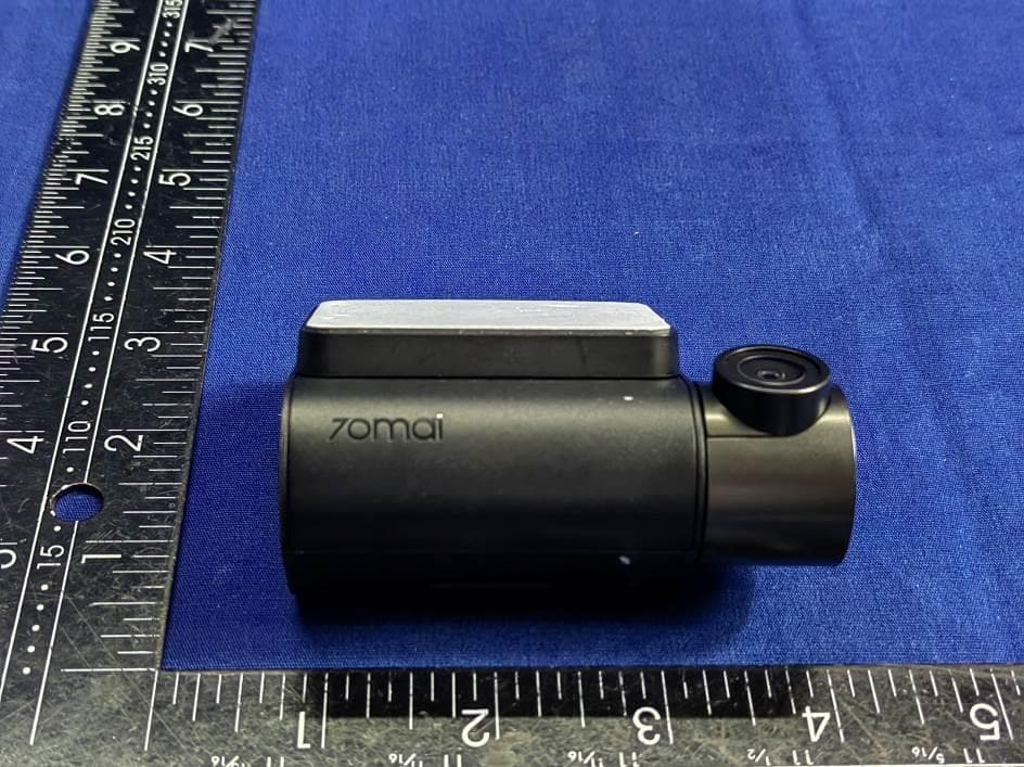
2AOK9-A200
Aug 26, 2023Dash Cam
Equipment Class
DTS - Digital Transmission System