2AOKB-A8327Soundsync Bluetooth Transmitter
Anker Innovations Limited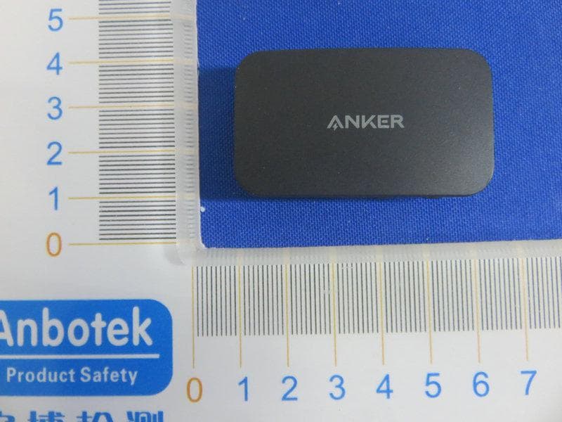
Click to zoom
Application Details
- Equipment Class
- DSS - Part 15 Spread Spectrum Transmitter
- Date of Grant
- May 23, 2020
- Application Purpose
- Original Equipment
- Date of Application
- May 23, 2020
- Equipment Note
- Soundsync Bluetooth Transmitter
- Frequency Range
- 2402.00000000 - 2480.00000000
- Company
- Anker Innovations Limited
- Country
- Hong Kong
Documents & Files
Document Text
Text extracted from the exhibit documents filed with the FCC. Open a document above to read the original.
Users Manual
f 01 f 02 f 03 f 04 f 05 f 06 Safety Instructions • Do not drop, knock, or shake the device. • Do not disassemble. Do not attempt to open the device. • Keep the device dry and away from all types of liquids or moisture that will corrode the electronic circuits. If the device gets wet, dry it immediately. • Avoid extreme temperatures. • Do not use outdoors during thunderstorms. • Use original or certified cables only. • Do not use any corrosive cleaner / oil to clean. The device should be charged at least once a month to preserve battery life. What’s Included Anker Bluetooth Transmitter User Manual User Manual Soundsync Bluetooth Transmitter 3.5 mm Audio Adapter micro USB Cable 3.5 mm Audio Cable At a Glance 1 Multi-function Button 5 Multipoint Connection LED Indicator 2 LED Indicator 6 Volume Down 3 3.5 mm AUX Input 7 Volume Up 4 Micro USB Charging Port • Charge the Bluetooth Transmitter before first use. • If Soundsync freezes, press and hold the multi-function button, insert the Micro USB cable to start charging, then restart Soundsync. LED Indicator Guide Flashing blue twicePower on Flashing red twicePower off Flashing red and blue alternatelyBluetooth pairing mode Steady blue Connected to a device / Connected to two devices simultaneously Flashing blue once every 2 seconds Disconnected from a device Flashing blue once every second Reconnected to a device Steady blue (LED indicator and Multipoint connection LED indicator) Two devices are connected simultaneously Flashing red and blue alternately Pairing deleted Using Your Soundsync Turn on / off 3S 3S 3S 3S ONPress and hold for about 3 seconds OFFPress and hold for about 3 seconds Connect Soundsync to a Bluetooth Device 3S 3S x2 1. When Soundsync is turned on, press the multifunction button twice to enter Bluetooth pairing mode. The LED indicator will flash red and blue alternately. 2. Enable Bluetooth on your Bluetooth headphones or speaker and pair it with Soundsync. When successfully paired, the LED indicator will turn blue. 3. Connect Soundsync to your device using the provided 3.5 mm audio cable. USER MANUAL Soundsync Bluetooth Transmitter For FAQs and more information, please visit: Product Number: A8327 Soundsync Bluetooth Transmitter 5100500XXXX V01 f 07 f 08 f 09 f 10 f 11 f 12 f 13 f 14 Charging Your Soundsync Flashing red Low battery Steady redCharging (When Soundsync is turned off) Off Fully Charged • Use the included Micro USB cable to charge your Soundsync and make sure it is fully charged before first use. • When not in use, store your Soundsync in a cool place. Specifications Specifications are subject to change without notice. DC input5V 0.5A Battery capacity 180mAh AUX playtime12 hours Charging time 2 hours Bluetooth versionV5.0 Support formatA2DP AVRCP Supported codec apt TM X Low Latency apt TM X SBC Size50 × 29 × 10 mm / 2.0 × 1.1 × 0.4 in Weight (without packaging)13.5g / 0.5oz Operating temperature range14F to 131F / -10C to 55 Range 10 m / 33 ft Declaration of Conformity Hereby, Anker Innovations Limited declares that the radio equipment type A8327 is in compliance with Directive 2014/53/EU. The full text of the EU declaration of conformity is available at the following internet address: https://www.anker.com Maximum output power: 3.891 dBm Frequency band: 2.4G band (2.4000GHz-2.4835GHz) FCC Statement This device complies with Part 15 of the FCC Rules. Operation is subject to the following two conditions: (1) This device may not cause harmful interference, and (2) this device must accept any interference received, including interference that may cause undesired operation. Warning: Changes or modifications not expressly approved by the party responsible for compliance could void the user's authority to operate the equipment. Note: This equipment has been tested and found to comply with the limits for a Class B digital device, pursuant to Part 15 of the FCC Rules. These limits are designed to provide reasonable protection against harmful interference in a residential installation. This equipment generates, uses, and can radiate radio frequency energy and, if not installed and used in accordance with the instructions, may cause harmful interference to radio communications. However, there is no guarantee that interference will not occur in a particular installation. If this equipment does cause harmful interference to radio or television reception, which can be determined by turning the equipment off and on, the user is encouraged to try to correct the interference by one or more of the following measures: - Reorient or relocate the receiving antenna. - Increase the separation between the equipment and receiver. - Connect the equipment into an outlet on a circuit different from that to which the receiver is connected. - Consult the dealer or an experienced radio / TV technician for help. Radiation Exposure Statement The device has been evaluated to meet general RF exposure requirement. The device can be used in portable exposure condition without restriction. The following importer is the responsible party. Company Name: Fantasia Trading LLC Address: 5350 Ontario Mills Pkwy, Suite 100, Ontario, CA 91764 Telephone: +1-800-988-7973 Anker Innovations Limited Room 1318-19, Hollywood Plaza, 610 Nathan Road, Mongkok, Kowloon, Hong Kong Connect Soundsync to two devices at the same time 1. Follow the steps in the “Connecting Soundsync to a Bluetooth device” section to connect Soundsync to the first Bluetooth headphone or speaker. 2. Press the multifunction button twice to re-enter Bluetooth pairing mode. 3. Enable Bluetooth onthe second Bluetooth headphone or speaker and pair it with Soundsync. When successfully paired, the LED indicator and Multipoint connection LED indicator will turn blue simultaneously. 4. Connect Soundsync to your device using the provided 3.5 mm audio cable. Now you can listen to music from both Bluetooth headphones or speakers. If there is still no sound coming from your devices devices, turn off So…
Text truncated - open the document above for the full version.
External Photos
FCCID:2AOKB-A8327
ID Label/Location Info
LabelLocationOnEUT Label ProductName:SoundsyncBluetoothTransmitter ModelNo.:A8327 FCCID:2AOKB-A8327 ThisdevicecomplieswithPart15oftheFCCRules.Operation issubjecttothefollowingtwoconditions: (1)Thisdevicemaynotcauseharmfulinterference,and (2)Thisdevicemustacceptanyinterferencereceived,including interferencethatmaycauseundesiredoperation.
Internal Photos
FCCID:2AOKB-A8327 ANT
Operational Description
version01 AnkerInnovationsLimited DeclarationconcerningAntennaSpecification Itisherebydeclaredthattheproduct ModelNo.:A8327 FCCID:2AOKB-A8327 fulfillstherequirementinFCCtestrelatingtotheantennatype. ThedevicespecifiedaboveconfirmstotheFCCrecommendationsforinternalantennatype(s) describedbelow: ModelNo.ofantenna:A8327 Typeofantenna:CeramicAntenna Gainoftheantenna:2dBi Frequencyrange:2402~2480MHz Themountingoftheantennaisfixedtotheradiomoduleandnootherantennashouldbeused. Companyname: AnkerInnovationsLimited Address:Room1318-19,HollywoodPlaza,610NathanRoad,Mongkok,Kowloon, HongKong City:Kowloon ZIP/Postalcode:N/A Country:HongKong Place:KowloonDate: 2020-05-22 Signature:
RF Exposure Info
RF EXPOSURE EVALUATION FCC ID: 2AOKB-A8327 According to FCC 1.1310: The criteria listed in the following table shall be used to evaluate the environment impact of human exposure to radio frequency(RF) Radiation as specified in §1.1307(b): Routine SAR evaluation refers to that specifically required by §2.1093, using measurements or computer simulation. When routine SAR evaluation is not required, portable transmitters withoutput power greater than the applicable low threshold require SAR evaluation to qualify for TCB approval. Channel (MHz) Maximum output power (dBm) Tune up tolerance (dBm) Max Tune Up Power (dBm) Distance (mm) Calculation results Limit Operating Mode 24023.575 3.575±14.57550.8893 BDR+EDR 24413.891 3.891±14.89150.9643 24803.553 3.553±14.55350.8993 24022.536 2.536±13.53650.7003 24413.131 3.131±14.13150.8093 24802.903 2.903±13.90350.7743 Test Results:PASS.
Test Report
Report No.: 18220WC00047701FCC ID: 2AOKB-A8327Page 1 of 50 Code:AB-RF-05-a FCC TEST REPORT Client Name: Anker Innovations Limited Address: Room 1318-19, Hollywood Plaza, 610 Nathan Road, Mongkok, Kowloon, Hong Kong Product Name: Soundsync Bluetooth Transmitter Date: May 21, 2020 Shenzhen Anbotek Compliance Laboratory Limited Report No.: 18220WC00047701FCC ID: 2AOKB-A8327Page 2 of 50 Code:AB-RF-05-a Contents 1. General Information ............................................................................................................................................... 5 1.1. Client Information ....................................................................................................................................... 5 1.2. Description of Device (EUT) ..................................................................................................................... 5 1.3. Auxiliary Equipment Used During Test ................................................................................................... 5 1.4. Description of Test Modes ........................................................................................................................ 6 1.5. List of channels ........................................................................................................................................... 7 1.6. Description Of Test Setup ......................................................................................................................... 8 1.7. Test Equipment List .................................................................................................................................... 9 1.8. Measurement Uncertainty ....................................................................................................................... 10 1.9. Description of Test Facility ...................................................................................................................... 10 2. Summary of Test Results ................................................................................................................................... 11 3. Conducted Emission Test ................................................................................................................................... 12 3.1. Test Standard and Limit .......................................................................................................................... 12 3.2. Test Setup .................................................................................................................................................. 12 3.3. Test Procedure .......................................................................................................................................... 12 3.4. Test Data .................................................................................................................................................... 12 4. Radiation Spurious Emission and Band Edge ................................................................................................ 17 4.1. Test Standard and Limit .......................................................................................................................... 17 4.2. Test Setup .................................................................................................................................................. 17 4.3. Test Procedure .......................................................................................................................................... 18 4.4. Test Data .................................................................................................................................................... 19 5. Maximum Peak Output Power Test .................................................................................................................. 27 5.1. Test Standard and Limit .......................................................................................................................... 27 5.2. Test Setup .................................................................................................................................................. 27 5.3. Test Procedure .......................................................................................................................................... 27 5.4. Test Data .................................................................................................................................................... 27 6. 20DB Occupy Bandwidth Test ........................................................................................................................... 31 6.1. Test Standard ............................................................................................................................................ 31 6.2. Test Setup .................................................................................................................................................. 31 6.3. Test Procedure .......................................................................................................................................... 31 6.4. Test Data .................................................................................................................................................... 31 7. Carrier Frequency Separation Test ................................................................................................................... 35 7.1. Test Standard and Limit .......................................................................................................................... 35 7.2. Test Setup .................................................................................................................................................. 35 7.3. Test Procedure .........................................................................................................................................…
Text truncated - open the document above for the full version.
Test Setup Photos
FCCID:2AOKB-A8327 PhotoofConductedEmissionMeasurement PhotoofRadiationEmissionTest
Contact Information
Applicant
Louis Qi
Test Firm
Shenzhen Anbotek Compliance Laboratory LimitedJeff Zhu
Technical Specifications
| # | Rule Parts | Frequency Range | Power Output |
|---|---|---|---|
| 1 | 15C | 2.40 GHz - 2.48 GHz | 2.50 mW |
Other Applications from Anker Innovations Limited
2AOKB-AS510
Sep 15, 2026Anker SOLIX S5000 Portable Power Station
Equipment Class
DTS - Digital Transmission System2AOKB-A1664B
Aug 26, 2026Anker MagGo Power Bank (10K,Slim)
Equipment Class
DCD - Part 15 Low Power Transmitter Below 1705 kHz2AOKB-A1665A
Aug 26, 2026Anker Nano Power Bank (5K, MagGo, Slim)
Equipment Class
DCD - Part 15 Low Power Transmitter Below 1705 kHz2AOKB-D1105R
Aug 20, 2026ANKER AeroClip 2
Equipment Class
DTS - Digital Transmission System2AOKB-D1105L
Aug 20, 2026ANKER AeroClip 2
Equipment Class
DTS - Digital Transmission System