2AOL7UWISINDS100UWIS Inductive module S
UWIS Oy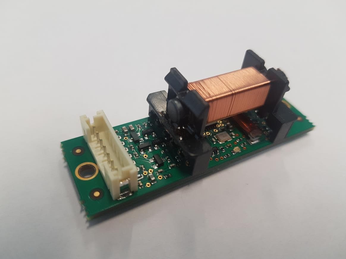
Click to zoom
Application Details
- Equipment Class
- DXT - Part 15 Low Power Transceiver, Rx Verified
- Date of Grant
- Jul 23, 2020
- Application Purpose
- Original Equipment
- Date of Application
- Jul 23, 2020
- Equipment Note
- UWIS Inductive module S
- Frequency Range
- 0.12300000 - 0.12300000
- Company
- UWIS Oy
- Country
- Finland
Documents & Files
Document Text
Text extracted from the exhibit documents filed with the FCC. Open a document above to read the original.
Users Manual
UWIS Oy, Kaarinantie 700 20540 Turku, Finland [email protected] +358 40 514 0565 www.uwis.fi UWIS INDUCTIVE MODULE UWIS-INDS100 OPERATION DESCRIPTION AND USER MANUAL A wireless inductive data link for digital data transmission above and under water REVISION 1.0 - April 2018 T.Toivola REVISION 2.0 - April 2020 T.Toivola (RF power, gain and duty cycle added) REVISION 3.0 - June 2020 T.Toivola (Chapter 9, No RX only mode) REVISION 4.0 - July 2020 P.Arvonen (Chapter 10) UWIS Oy, Kaarinantie 700 20540 Turku, Finland [email protected] +358 40 514 0565 www.uwis.fi Contents UWIS INDUCTIVE MODULE........................................................................................... 1 UWIS-INDS100................................................................................................................. 1 OPERATION DESCRIPTION .......................................................................................... 1 1. Object of the Document .............................................................................................. 2 2. Features ...................................................................................................................... 2 3. Operating frequencies ................................................................................................. 3 4. Modulation ................................................................................................................. 3 5. Host interface.............................................................................................................. 4 6. MCU ............................................................................................................................ 4 7. TX amplifier ................................................................................................................. 4 8. RX amplifier ................................................................................................................ 5 9. Module usage position ................................................................................................ 5 10. FCC Statement ........................................................................................................... 7 1. Object of the Document This document contains description the functional operation of the UWIS Inductive module and user manual. 2. Features Nominal features for UWIS UWIS-INDS100 inductive link are as follows: 1 The device implements the current UWC protocol specification 2 Communication range is 1.5 meters minimum 3 Frame error rate is less than 1% at 1.0 meter range 4 There are no interference to another UWC device 5 The device accept typical outside interference while maintaining communication range and frame error rate specifications UWIS Oy, Kaarinantie 700 20540 Turku, Finland [email protected] +358 40 514 0565 www.uwis.fi 3. Operating frequencies Divisors using an 8 MHz peripheral clock (PERCLK) are shown in Table 1 with operating frequencies. Table 1 Operating frequencies. TXFREQ Transmit carrier frequency 123076.92 Hz PERCLK / 65 TXPEAKPOWER Transmit peak power 25 dBm TXDUTYCYCLE Transmit duty cycle 20 ms / 1000ms ANTENNAGAIN Integral coil antenna gain 2.15 dBi max BITRATE Bit rate 8791.21 Hz TXFREQ / 14 SAMPLERATE Receiver Sample Rate 43956.04 Hz PERCLK/182 RXFREQ Receive carrier frequency 123076.92 Hz RS232 Serial data bit rate 115200 baud 4. Modulation The UWC inductive link uses binary phase-shift keying (BPSK) modulation. The BPSK modulation works by shifting the phase of the transmit carrier by 180 degrees for every transmit bit that is zero. When the transmit bit is one, the carrier is transmitted without change. The bandwidth used is roughly equal to the bit rate. UWIS Oy, Kaarinantie 700 20540 Turku, Finland [email protected] +358 40 514 0565 www.uwis.fi 5. Host interface Inductive module is connected to the host with 7-pin interface cable. Table 2 Host interface Pin Name Signal Value 1 3V 3V regulated supply 3V +-5% 2 USORX RS232 serial bus TX 115200 baud 8N2 0/3V 3 USOTX RS232 serial bus TX 115200 baud 8N2 0/3V 4 GND Ground 5 Mute Mute control to switch off TX 0/3V control line 6 - Reserved 7 12V 12V regulated supply 12V +-5% 6. MCU MCU EMF32G210 convert serial data to inductive TX-signal and receive inductive RX-signal converting it to serial data. MCU runs with 16MHz clock generating needed frequencies according embedded firmware. 7. TX amplifier MCU gives digital timing and modulation for external mux. Mux gives modulated digital output for transmitter output amplifier. Digital signal is then filtered to analog signal with needed bandwidth. Analog signal is possible to mute with host mute signal to avoid known collisions. Analog amplifier feeds output coil. Output coil is tuned to 123 kHz to achieve needed range. UWIS Oy, Kaarinantie 700 20540 Turku, Finland [email protected] +358 40 514 0565 www.uwis.fi 2-INPUT MUX BAND PASS FILTER MUTE 12V 3V TIMING/MODULATION FROM MCU AMP RESONANCE ANTENNA Figure 1 Transmitter block diagram 8. RX amplifier Receiver coil is tuned to max receiver sensitivity. Low noise amplifier amplify received signal for MCU ADC conversion. MCU receive differential signal for BPSK detection. There is no RX only function mode on this device, TX is always functional and so receiver only mode cannot be measured. AMP AMP TO MCU ADC RX RESONANCE ANTENNA Figure 2 Receiver block diagram 9. Module usage position Inductive module is located inside the host enclosure to achieve mechanical, moisture or ESD protection. Host device nominal location and direction gives optimal range for inductive antenna. UWIS Oy, Kaarinantie 700 20540 Turku, Finland [email protected] +358 40 514 0565 www.uwis.fi 1 7 1 7 JST PHR7 PHR7 TX RADIATION PATTERN TX ANT RX ANT 20 60 Figure 3 Module antenna and connector locations Figure 4 UWIS-INDS100 picture UWIS Oy, Kaarinantie 700 20540 Turku, Finland [email protected] +358 40 514 0565 www.uwis.fi 10. FCC Statement This device complies with part 15 of the FCC Rules. Operation is subj…
Text truncated - open the document above for the full version.
Cover Letter(s)
Scanned by CamScanner
Cover Letter(s)
Scanned by CamScanner Scanned by CamScanner
Cover Letter(s)
Scanned by CamScanner
RF Exposure Info
Reference number: 290154-3-1 Page 1 of 10 These test results are valid for the tested unit only. This report shall not be reproduced, except in full, without a written permission of SGS Fimko. Test Report INTENTIONAL RADIATOR TESTS ACCORDING TO FCC PART 15 C Equipment Under Test: Inductive communication module (123 kHz) Model: UWIS-INDS100 Manufacturer: UWIS Oy Kaarinantie 700 20540 Turku FINLAND Customer: UWIS Oy Kaarinantie 700 20540 Turku FINLAND FCC Rule Part: 15.209: 2016 Date: 30 June 2020 Date: 30 June 2020 Issued by: Checked by: Jani Tuomela Rauno Repo Testing Engineer Testing Engineer Reference number: 290154-3-1 Page 2 of 10 Table of Contents GENERAL REMARKS ................................................................................................................................... 3 Disclaimer ................................................................................................................................................. 3 RELEASE HISTORY...................................................................................................................................... 4 PRODUCT DESCRIPTION ............................................................................................................................ 5 Equipment Under Test .............................................................................................................................. 5 General Description .................................................................................................................................. 5 Ratings and declarations ........................................................................................................................... 5 Power Supply ............................................................................................................................................ 5 Mechanical Size of the EUT ...................................................................................................................... 5 SUMMARY OF TESTING .............................................................................................................................. 6 EUT Test Conditions during Testing .......................................................................................................... 6 TEST RESULTS ............................................................................................................................................ 7 Transmitter Radiated Spurious Emissions 9 kHz - 2 GHz .......................................................................... 7 TEST EQUIPMENT ....................................................................................................................................... 10 Reference number: 290154-3-1 Page 3 of 10 General Remarks GENERAL REMARKS Disclaimer This document is issued by the Company subject to its General Conditions of Service printed overleaf, available on request or accessible at http://www.sgs.com/en/Terms-and-Conditions.aspx and, for electronic format documents, subject to Terms and Conditions for Electronic Documents at http://www.sgs.com/en/Terms-and-Conditions/Terms-e-Document.aspx Attention is drawn to the limitation of liability, indemnification and jurisdiction issues defined therein. Any holder of this document is advised that information contained hereon reflects the Company’s findings at the time of its intervention only and within the limits of Client’s instructions, if any. The Company’s sole responsibility is to its Client and this document does not exonerate parties to a transaction from exercising all their rights and obligations under the transaction documents. This document cannot be reproduced except in full, without prior written approval of the Company. Any unauthorized alteration, forgery or falsification of the content or appearance of this document is unlawful and offenders may be prosecuted to the fullest extent of the law. Unless otherwise stated the results shown in this test report refer only to the sample(s) tested and such sample(s) are retained for 30 days only. Reference number: 290154-3-1 Page 4 of 10 Release History Test Report template version: 1.3 RELEASE HISTORY Version Changes Issued 1.0 Initial release 30 June 2020 Reference number: 290154-3-1 Page 5 of 10 Product Description PRODUCT DESCRIPTION Equipment Under Test Trade mark: - Model: UWIS-INDS100 Type: Inductive communication module Serial no: - FCC ID: - IC: - General Description EUT is an Inductive low frequency transceiver (DXT) communication module with 123 kHz operating frequency. Classification Fixed device Mobile Device (Human body distance > 20cm) Portable Device (Human body distance < 20cm) Modifications Incorporated in the EUT No modifications were applied to the EUT during testing Ratings and declarations Operating Frequency Range (OFR): 123 kHz Channels: 1 Channel separation: - Transmission technique: - Modulation: - Output power (peak): 25 dBm (declared by the customer) Antenna type: Coil antenna Integral Antenna gain: 2.15 dBi max Power Supply Operating voltage range: 12 VDC During the test, EUT was powered with 12 V battery back. Mechanical Size of the EUT Height: 17 mm Width: 60 mm Length: 20 mm Reference number: 290154-3-1 Page 6 of 10 Summary of Testing SUMMARY OF TESTING Test Specification Description of Test Result §15.209(a) Radiated Emissions 9 kHz to 2 GHz PASS The decision rule applied for the tests results stated in this test report is according to the requirements of section 1.3 of ANSI C63.10-2013. EUT Test Conditions during Testing The EUT was operating on 123 kHz and was in continuous transmit/receive mode during all the tests. EUT was transmitting and receiving alternately. DC input (12/24 VDC) Figure 1: Test setup blocking diagram Test Facility Testing Laboratory / address: FCC designation number: FI0002 ISED CAB identifier: T004 SGS Fimko Ltd Takomotie 8 FI-00380, HELSINKI FINLAND Test Site: ☐ K10LAB, ISED Canada …
Text truncated - open the document above for the full version.
Test Report
Reference number: 290154-1-1 Page 2 of 12 Table of Contents PRODUCT DESCRIPTION .................................................................................................................................. 3 Equipment Under Test (EUT) .......................................................................................................................... 3 Power Requirements ....................................................................................................................................... 3 Samples ........................................................................................................................................................... 3 Peripherals ...................................................................................................................................................... 3 GENERAL REMARKS .......................................................................................................................................... 4 Disclaimer ........................................................................................................................................................ 4 SUMMARY OF TESTING ..................................................................................................................................... 5 Summary of Testing ........................................................................................................................................ 5 EUT Test Conditions during Testing ............................................................................................................... 5 TEST RESULTS ................................................................................................................................................... 6 Conducted Emissions In The Frequency Range 150 kHz - 30 MHz. .............................................................. 6 Radiated Emissions In The Frequency Range 9 KHz to 26500 MHz ............................................................. 8 TEST EQUIPMENT .............................................................................................................................................. 12 Reference number: 290154-1-1 Page 3 of 12 Product Description PRODUCT DESCRIPTION Equipment Under Test (EUT) UWIS is an underwater navigation, communications and surveillance system that utilizes the triangulation princi- ple. With UWIS’s help the divers’ underwater location can be determined with just a few meters accuracy. It also enables communication between the dive participants and the surface via pre-set messages. The dive data is relayed to the surface via a buoy and the dive leaders can use the UWIS-software to track the progress of the divers in real time. Recording of the data helps to analyze and plan the dive missions. The system can track up to 100 divers simultaneously over an area of 800 meters across an in depth of 150 meters. UWIS system consists of three buoys and a diver unit that is attached on the air tank. The system communicates underwater via ultrasound. The diver unit is attached on the air tank and it connects to the display wirelessly via Bluetooth, Wi-Fi or inductive data transfer. The communications between a diver unit and the master buoy are carried out via ultrasound. Diver unit for UWIS system This report contains the results for diver unit. Power Requirements The EUT is a battery-operated device. Samples One Sample was used for testing. No modifications were made during the testing. Peripherals - Wireless charger: Model VUSOLOGY-T; Input DC 5V, 1.8A; Output 5W - Charger: Model Samsung EP-TA12EWE; Input 100-240V 50/60Hz, 0.35A; Output 5.0V, 2.0A All peripherals were supplied by the manufacturer. Radio Interface Manufacture r Model No.Mode Operating Freq Tx pow er Distance to User Sim ultaneous transm ission FCC IDGrantISED ID Mobile / Portable AntennaNotes b 15 dBm, Average g 14 dBm, Average [b] Bluetooth 4.2 BLE RigadoBMD-300BLE2,4 GHz 4 dBm, Average more than 20cm Possible w ith [a], [c] 2AA9B04Limited12208A-04 Mobile (module) Integrated on PWB, Gain 0 dBi Integral Antenna (original) [c]Low Pow erUWIS UWIS- INDS100 -123 kHz 25 dBm, Peak more than 20cm Possible w ith [a], [b] --No- Integrated, Gain 2.15 dBi Inductive communication module, UWIS- INDS100 [e] Wireless Charging --- 100-200 kHz -------- Receiver Unit self designed [f ] Ultrasonic transmitter ---56 kHz200 W- Used f or communication w ith buoy -----Pulses 300ms Integral Antenna (original) Modular 9154A- GS21000MIP Mobile (module) Integrated on PWB, Gain 1 dBi GS2100MIP[a]Wi-Fi moduleGainspan2,4 GHz more than 20cm Possible w ith [b], [c] YOPGS2100MIP Reference number: 290154-1-1 Page 4 of 12 Test Conditions GENERAL REMARKS Disclaimer This document is issued by the Company under its General Conditions of service accessible at http://www.sgs.com/terms_and_conditions.htm. attention is drawn to the limitation of liability, indemnifica- tion and jurisdiction issues defined therein. Any holder of this document is advised that information contained hereon reflects the Company's findings at the time of its intervention only and within the limits of Client's instructions, if any. The Company's sole responsibil- ity is to its Client and this document does not exonerate parties to a transaction from exercising all their rights and obligations under the transaction documents. Any unauthorized alteration, forgery or falsification of the con- tent or appearance of this document is unlawful and offenders may be prosecuted to the fullest extent of the law. Unless otherwise stated the results shown in this test report refer only to the sample(s) tested and such sam- ple(s) are retained for 90 days only. This document cannot be reproduced except in full, without prior approval of the Company. Reference number: 290154-1-1 Page 5 of 12 Summary of Testing SUMMARY OF TESTING Summary of Testing Test Specification Description of Test Test site Resu…
Text truncated - open the document above for the full version.
Test Report
UWIS Oy, Kaarinantie 700 20540 Turku, Finland [email protected] +358 40 514 0565 www.uwis.fi UWIS INDS100 MPE CALCULATION Inductive communication module maximum permissible exposure REVISION 1.0 - June 2019 T.Toivola UWIS Oy, Kaarinantie 700 20540 Turku, Finland [email protected] +358 40 514 0565 www.uwis.fi Contents UWIS INDS100 MPE CALCULATION............................................................................ 1 1. Object of the Document .............................................................................................. 2 2. FCC regulation limits ................................................................................................... 2 3. MPE calculation ........................................................................................................... 3 4. Result .......................................................................................................................... 3 1. Object of the Document Description of inductive transmitter maximum permissible exposure. 2. FCC regulation limits Limits for Maximum Permissible Exposure (MPE) - from §1.1310 Frequency Range (MHz) Electric Field Strength (V/m) Magnetic Field Strength (A/m) Power Density (mW/cm2) Averaging Time (minutes) 0.3-3.0 614 1.63 100 † 6 3.0-30 1842/f 4.89/f 900/f2 † 6 30-300 61.4 0.163 1.0 6 300-1500 - - f/300 6 1500-100,000 - - 5 6 Limits for General Population/Uncontrolled Exposure Frequency Range (MHz) Electric Field Strength (V/m) Magnetic Field Strength (A/m) Power Density (mW/cm2) Averaging Time (minutes) 0.3-3.0 614 1.63 100 † 30 3.0-30 842/f 2.19/f 180/f2 † 30 30-300 27.5 0.073 0.2 30 300-1500 - - f/1500 30 1500-100,000 - - 1.0 30 f = frequency in MHz † = plane-wave equivalent power density (see note) Note: Equivalent far field strength that would have the E-field or H-field components calculated or measured. Equivalent far field density for near and far fields can be calculated using Power Density = |Etotal|2/3770 mW/cm2 or Power Density = |Htotal|2/37.7 mW/cm2 UWIS Oy, Kaarinantie 700 20540 Turku, Finland [email protected] +358 40 514 0565 www.uwis.fi 3. MPE calculation Transmit carrier frequency 123076.92 Hz binary phase-shift keying (BPSK) modulation Peak power 25 dBm = 316 mW Pulsed average 20 ms / 1000 ms x 316 mW = 6,32 mW Antenna gain estimated < 2 S = (P x G)/(4 x π x d^2) – used to calculate exposure at 20 cm Distance Power Gain Exposure D / cm P / mW G S / mW/cm2 20 6,32 2 0,00251465 4. Result MPE calculation shows that the total power density at 20cm is less than FCC limits.
Test Setup Photos
Test Setup Photographs 1 (4) 290154-1-1 UWIS, Diver unit SGS Fimko Ltd Särkiniementie 3, PO Box 30 FI-00211 Helsinki, Finland t. +358 9 696 361 f. +358 9 692 5474 www.fi.sgs.com Business ID 0978538-5 Member of the SGS Group (SGS SA) Photograph 1. DUT Photograph 2. Wireless charging unit and charger Test Setup Photographs 2 (4) 290154-1-1 UWIS, Diver unit SGS Fimko Ltd Särkiniementie 3, PO Box 30 FI-00211 Helsinki, Finland t. +358 9 696 361 f. +358 9 692 5474 www.fi.sgs.com Business ID 0978538-5 Member of the SGS Group (SGS SA) Photograph 3. Wireless charging unit Photograph 4. Radiated Spurious Emissions 9 KHz - 30 MHz Test Setup Photographs 3 (4) 290154-1-1 UWIS, Diver unit SGS Fimko Ltd Särkiniementie 3, PO Box 30 FI-00211 Helsinki, Finland t. +358 9 696 361 f. +358 9 692 5474 www.fi.sgs.com Business ID 0978538-5 Member of the SGS Group (SGS SA) Photograph 5. Radiated Spurious Emissions 30 – 1000 MHz Photograph 6. Radiated Spurious Emissions 1 – 18 GHz Test Setup Photographs 4 (4) 290154-1-1 UWIS, Diver unit SGS Fimko Ltd Särkiniementie 3, PO Box 30 FI-00211 Helsinki, Finland t. +358 9 696 361 f. +358 9 692 5474 www.fi.sgs.com Business ID 0978538-5 Member of the SGS Group (SGS SA) Photograph 7. Radiated Spurious Emissions 18 – 26.5 GHz Photograph 8. Conducted spurious emissions test set-up
Test Setup Photos
Test Setup Photographs 1 (4) 290154-3-1 UWIS, Low frequency transceiver module SGS Fimko Ltd. Takomotie 8, FI-00380 Helsinki Finland t +358 9 6963 361 f +358 9 692 5474 www.sgs.fi Member of SGS Group (Société Générale de Surveillance) Photograph 1. DUT 1 Photograph 2. DUT 1 and power unit Test Setup Photographs 2 (4) 290154-3-1 UWIS, Low frequency transceiver module SGS Fimko Ltd. Takomotie 8, FI-00380 Helsinki Finland t +358 9 6963 361 f +358 9 692 5474 www.sgs.fi Member of SGS Group (Société Générale de Surveillance) Photograph 3. Radiated Spurious Emissions 9 kHz - 30 MHz Photograph 4. Radiated Spurious Emissions 30 – 1000 MHz Test Setup Photographs 3 (4) 290154-3-1 UWIS, Low frequency transceiver module SGS Fimko Ltd. Takomotie 8, FI-00380 Helsinki Finland t +358 9 6963 361 f +358 9 692 5474 www.sgs.fi Member of SGS Group (Société Générale de Surveillance) Photograph 5. Radiated Spurious Emissions 1 – 2 GHz Photograph 6. EUT on table Test Setup Photographs 4 (4) 290154-3-1 UWIS, Low frequency transceiver module SGS Fimko Ltd. Takomotie 8, FI-00380 Helsinki Finland t +358 9 6963 361 f +358 9 692 5474 www.sgs.fi Member of SGS Group (Société Générale de Surveillance) Photograph 7. EUT on table
Contact Information
Applicant
Pertti Kalevi Arvonen(CEO)
Technical Contact
Non-Technical Contact
UWIS OyPertti Arvonen
[email protected]358 40 5140565
Test Firm
SGS Fimko OyJanne Nyman
Technical Specifications
| # | Rule Parts | Frequency Range | Power Output |
|---|---|---|---|
| 1 | 15C | 0.123 MHz - 0.123 MHz | - |