2AOR81909004Wireless Charger providing a USB Type-C interface
etatronix GmbH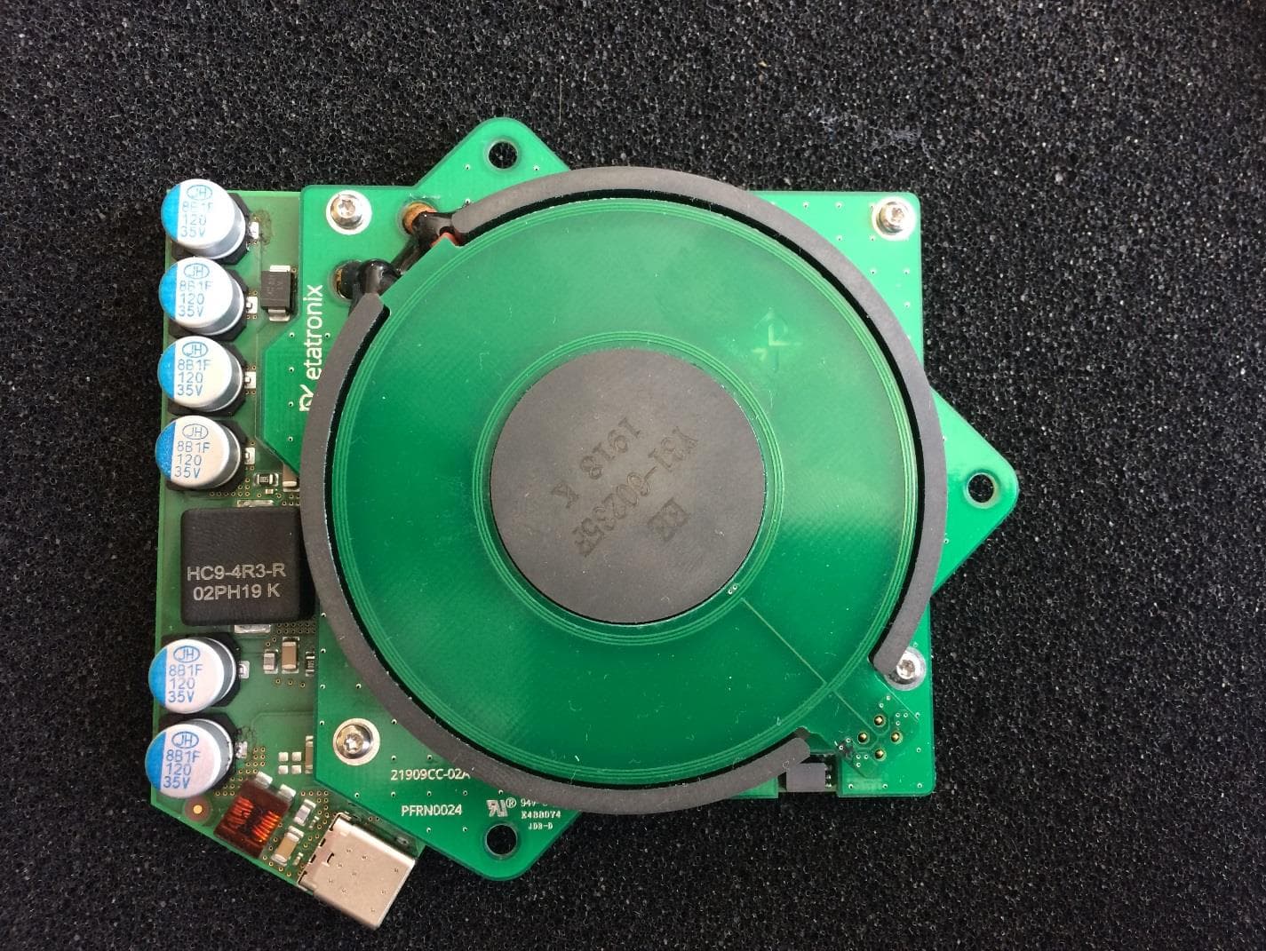
Click to zoom
Application Details
- Equipment Class
- DCD - Part 15 Low Power Transmitter Below 1705 kHz
- Date of Grant
- Feb 25, 2020
- Application Purpose
- Original Equipment
- Date of Application
- Feb 25, 2020
- Equipment Note
- Wireless Charger providing a USB Type-C interface
- Frequency Range
- 0.11100000 - 0.14900000
- Company
- etatronix GmbH
- Country
- Germany
Documents & Files
Document Text
Text extracted from the exhibit documents filed with the FCC. Open a document above to read the original.
Users Manual
Installation Guide Installation Guide 1. Purpose The purpose of this document is to provide information on how to integrate the Wireless Power Transmitter (Model: 81909005) and Receiver (Model: 81909004) with FCC ID: 2AOR81909004 into a final application. Incorrect integration or use may infringe compliance rules meaning recertification may be required. 2. Module Description The Wireless Power modules (Tx= power transmitter, Rx = power receiver) are designed to provide a high efficiency power transmission of up to 13.5W to an USB Type-C device. This power transmission is using a pair of tightly coupled power coils. An additional pair of inductive coupled coils is used to transfer control information from the power receiver back to the transmitter to provide a safe operation at the optimum working frequency. The power transmission module input voltage is 24V DC. To maximize the system efficiency, the power transmission between Wireless Transmitter and Receiver is realized using resonant circuits. These resonant circuits additionally provide the ability to vary the transmitted power by changing the switching frequency. By increasing the switching frequency, the available power on the receiver side de-creases. For an accurate output voltage regulation, a control loop is necessary. The output conditions like output current, voltage and power are measured on the receiver side and sent to the power transmitter. If corrections are necessary, the transmitter will change the switching frequency to the desired value. An appropriate control loop needs a fast signal transmission with little delay. This transmission is accomplished using a second pair of coupled coils. Like the power transmission coils, the signal coils form a near field coupling system thus the intended use of radio waves isn’t necessary. Installation Guide The following picture shows a block diagram of the complete system including Transmitter and Receiver. Installation Guide 3. Application Examples The system is designed to be used as a Wireless Charger for USB Type-C powered devices in medical environments (e.g. tablets). The Wireless Power Transmitter must be mounted on and powered by a base station. The Wireless Power Receiver can be connected with the USB Type-C device either using an USB type C compliant cable. The USB type-C device together with the Wireless Power Receiver can be used in mobile applications, the base station including the Wireless Power Transmitter is stationary and not intended for mobile usage. In order to start the charging process, the Power Receiver must be placed close to the Power Transmitter. Charging will only take place during non-mobile stationary usage. The power transmitter is stationary and the power receiver will be installed inside a non-stationary device. The power receiver and the device which will be charged are to be mounted in the same enclosure, so it’s not possible for hum The picture shows the use cases “Not Charging” and “Charging”. The Power Transmitter is depicted yellow, the Power Receiver red. The following pictures shows an example application where the Wireless Power Transmitter is wall mounted on a computer-tomography scan unit and the Receiver is connected to a tablet which is used for supervision. In this situation the tablet isn’t charging. Installation Guide The following pictures shows part of the front of a medical stationary device. The Transmitter is mounted behind the front and not accessible on back and side: The following pictures shows the backside of the front of the stationary medical device where the Transmitter is mounted: Installation Guide The following pictures shows the enclosure for both Wireless Receiver and tablet with Receiver mounted and tablet not mounted. The following pictures shows the enclosure for both Wireless Receiver and tablet with Receiver and tablet mounted. The tablet is connected with the Receiver using an USB-cable (see picture above and section “Integration into products”. USB Type C compliant Flex- Cable Receiver Enclosure Enclosure Enclosure USB Type C Connector connected with tablet Tablet USB Type-C Connector Tablet Installation Guide The following pictures shows the enclosure with tablet and Wireless Receiver put on top of the stationary medical device. This is the typical setup for the charging tablet: Installation Guide 4. Integration into Products Transmitter The input connector of the Wireless Power Transmitter is a TE Connectivity 1-178293-3. The Wireless Power Transmitter shall be mounted using the mounting holes provided by the manufacturer. M4 screws and hex nuts are recommended. Receiver The Wireless Power Receiver supplies a USB Type-C compliant power to the host application. The following picture shows the USB type C output connector: The Wireless Power Receiver shall be mounted using the mounting holes provided by the manufacturer. M3 screws are suitable, e.g. Screwerk STP 3803000803 or comparable. The cable to supply the load shall be USB Type-C compliant. Installation Guide The following picture shows the system mounted in a final example application without the tablet. Installation Guide 5. Antenna design The following picture shows the antenna design. The antenna is carried out on a 1mm PCB using traces of 200u width, the distance between the windings is 200u. As shown in various EMC tests, no intended radiation is used to transmit data. All information is transmitted using the principle of near field coupled coils utilizing a carrier frequency of 2MHz. The coil area used is 440 mm². Installation Guide 6. Regulatory Information FCC This device complies with Part 15 of FCC Rules, Operation is Subject to following two conditions: 1) This device may not cause harmful interference, and 2) This device must accept any interference received including Caution: Any changes or modifications to the equipment not expressly approved by the party responsible for compliance could void user’s authority to operate the equipment. Thi…
Text truncated - open the document above for the full version.
External Photos
External Photos External Photos Transmitter The following picture shows the Top View of the device: External Photos The following picture shows the Bottom View of the device External Photos The following picture shows the Side View of the device External Photos The following picture shows the Side View of the device External Photos The following picture shows the Side View of the device External Photos The following picture shows the Side View of the device External Photos Receiver The following picture shows the Top View of the device: External Photos The following picture shows the Bottom View of the device External Photos The following picture shows the Side View of the device External Photos The following picture shows the Side View of the device External Photos The following picture shows the Side View of the device
ID Label/Location Info
Labels Labels Labels Transmitter The following picture shows the Wireless Power Transmitter product label: Labels The following pictures show the position of the labels on the module: Labels RX The following picture shows the Wireless Power Receiver product label: Labels The following pictures show the position of the labels on the module: Labels
Internal Photos
Internal Photos Internal Photos Transmitter The following picture shows the Top View of the PCB: Internal Photos The following picture shows the Top View of the Power Coil with Data Coil: Internal Photos The following picture shows the Top View of the Power Coil: Internal Photos The following picture shows the Bottom View of the Power Coil: Internal Photos The following picture shows the Top View of the Data Coil: Internal Photos The following picture shows the Bottom View of the Data Coil: Internal Photos Receiver The following picture shows the Top View of the PCB without coils attached: Internal Photos The following picture shows the Top View of the Power Coil: Internal Photos The following picture shows the Bottom View of the Power Coil: Internal Photos The following picture shows the Top View of the Data Coil: Internal Photos The following picture shows the Bottom View of the Data Coil:
RF Exposure Info
© CTC advanced GmbH Page 1 of 12 TEST REPORT Test Report No.: 1-9990/20-01-02 Testing Laboratory Applicant CTC advanced GmbH Untertuerkheimer Strasse 6 – 10 66117 Saarbruecken/Germany Phone: + 49 681 5 98 - 0 Fax: + 49 681 5 98 - 9075 Internet: http://www.ctcadvanced.com e-mail: [email protected] Accredited Test Laboratory: The testing laboratory (area of testing) is accredited according to DIN EN ISO/IEC 17025 (2005) by the Deutsche Akkreditierungsstelle GmbH (DAkkS) The accreditation is valid for the scope of testing procedures as stated in the accreditation certificate with the registration number: D-PL-12076-01-01 etatronix GmbH Werschweilerstrasse 40 66606 St. Wendel/GERMANY Contact: Dominik Huwig e-mail: [email protected] Phone: +49 6851 90 74 27 1 Fax: +49 6851 90 74 27 9 Manufacturer etatronix GmbH Werschweilerstrasse 40 66606 St. Wendel/GERMANY Test Standard/s FCC - Title 47 CFR Chapter I - Subchapter I §1.1310 Radiofrequency radiation exposure limits. FCC KDB 680106 D01 Exposure Wireless Charging Apps v03 RF Exposure Considerations for Low Power Consumer Wireless Power Transfer Applications For further applied test standards please refer to section 3 of this test report. Test Item Kind of test item: wireless charger Device type: module Model name: consisting of transmitter (81909005) and receiver (81909004) FCC-ID: 2AOR81909004 Frequency: 111 - 149 kHz Antenna: Integrated antenna DC supply: 24V Auxiliary equipment: USB Power Delivery - Tester PM110 (load) Test sample status: identical prototype Exposure category: general population / uncontrolled environment This test report is electronically signed and valid without handwriting signature. For verification of the electronic signatures, the public keys can be requested at the testing laboratory. Test Report authorised: Test performed: Thomas Vogler Marco Scigliano Lab Manager Testing Manager Radio Communications Radio Communications Test report no.: 1-9990/20-01-02 © CTC advanced GmbH Page 2 of 12 1 Table of contents 1 Table of contents ....................................................................................................................................... 2 2 General information .................................................................................................................................. 3 2.1 Notes and disclaimer ..................................................................................................................... 3 2.2 Application details ......................................................................................................................... 3 2.3 Statement of compliance ............................................................................................................... 3 2.4 Technical details ............................................................................................................................ 4 2.5 Auxiliary equipment ....................................................................................................................... 4 3 Test standard/s: ......................................................................................................................................... 5 3.1 RF exposure limits ......................................................................................................................... 5 4 Summary of Measurement Results ......................................................................................................... 6 5 Test Environment ...................................................................................................................................... 6 6 Test Set-up ................................................................................................................................................. 7 6.1 Measurement system ..................................................................................................................... 7 6.1.1 Broadband Electromagnetic Field Test system ..................................................................... 7 6.1.2 Test equipment list ................................................................................................................ 8 6.1.3 Averaging............................................................................................................................... 8 6.1.4 Uncertainties .......................................................................................................................... 9 6.1.4.1 Typical uncertainty of EHP-50F ............................................................................................ 9 6.1.5 Definition of test position and distances ................................................................................ 9 6.2 Test results ................................................................................................................................... 10 6.3 Final verdict .................................................................................................................................. 11 Annex A: Photo documentation ............................................................................................................... 11 Annex B: Document History ..................................................................................................................... 12 Annex C: Further Information .................................................................................................................. 12 Test report no.: 1-9990/20-01-02 © CTC advanced GmbH Page 3 of 12 2 General information 2.1 Notes and disclaimer The test results of this test report relate exclusively to the test item specified in this test report. CTC advanced GmbH does not assume responsibility for any conclusions and generalisations drawn from the test results with regard to other specimens or samples of the type of the equipment represented by the test item. The test report may only be rep…
Text truncated - open the document above for the full version.
Test Report
UL INTERNATIONAL GERMANY GMBH Hedelfinger Str. 61 70327 Stuttgart, Germany [email protected] TEST REPORT Test Report No. : UL-RPT-RP-12698311-1216-FCC Applicant : Etatronix GmbH Model No. : Consisting of transmitter (81909005) and receiver (81909004) FCC ID : 2AOR81909004 Technology : Wireless Power Transfer with associated 2 MHz Data Communication Test Standard(s) : FCC Parts 15.205, 15.207, 15.209(a), 15.215 For details of applied tests refer to test result summary 1. This test report shall not be reproduced in full or partial, without the written approval of UL International Germany GmbH. 2. The results in this report apply only to the sample tested. 3. The test results in this report are traceable to the national or international standards. 4. Test Report Version 1.1 supersedes Version 1.0 with immediate effect Test Report No. UL-RPT-RP-12698311-1216-FCC Version 1.1,Issue Date 05 March 2020 supersedes Test Report No. UL-RPT-RP-12698311-1216-FCC Version 1.0,Issue Date 20 February 2020 ,which is no longer valid. 5. Result of the tested sample: PASS _________________________ _________________________ Prepared by: Abdoufataou, Salifou Approved by: Ajit, Phadtare Title: Laboratory Engineer Title: Lead Test Engineer Date: 05 March 2020 Date: 05 March 2020 This laboratory is accredited by DAkkS. The tests reported herein have been performed in accordance with its’ terms of accreditation. UL INTERNATIONAL GERMANY GMBH TEST REPORT NO: UL-R PT-RP-12698311-1216-FCC TEST REPORT VERSION 1.1 ISSUE DATE: 05 MARCH 2020 Page 2 of 35 FCC 15.209 - Template Vers. 1.5 This page has been left intentionally blank. UL INTERNATIONAL GERMANY GMBH TEST REPORT NO: UL-RPT-RP-12698311-1216-FCC TEST REPORT VERSION 1.1 ISSUE DATE: 05 MARCH 2020 Page 3 of 35 FCC 15.209 - Template Vers. 1.5 Table of Contents 1. Customer Information ................................................................................................................ 4 2. Summary of Testing ................................................................................................................... 5 2.1. General Information 5 Applied Standards 5 Location 5 Date information 5 2.2. Summary of Test Results 6 2.3. Methods and Procedures 6 2.4. Deviations from the Test Specification 6 3. Equipment Under Test (EUT) .................................................................................................... 7 3.1. Identification of Equipment Under Test (EUT) 7 3.2. Description of EUT 7 3.3. Modifications Incorporated in the EUT 7 3.4. Additional Information Related to Testing 8 3.5. Support Equipment 9 A. Support Equipment (In-house) 9 B. Support Equipment (Manufacturer supplied) 9 4. Operation and Monitoring of the EUT during Testing ............................................................10 4.1. Operating Modes 10 4.2. Configuration and Peripherals 10 5. Measurements, Examinations and Derived Results ...............................................................11 5.1. General Comments 11 5.2. Test Results 12 5.2.1. Transmitter AC Conducted Spurious Emissions 12 5.2.2. Transmitter 20 dB Bandwidth 17 5.2.3. Transmitter Fundamental Field Strength 20 5.2.4. Transmitter Radiated Spurious Emissions 24 6. Measurement Uncertainty ........................................................................................................29 7. Used equipment ........................................................................................................................30 8. Open-Area-Test Site comparison .............................................................................................31 9. Report Revision History ...........................................................................................................35 UL INTERNATIONAL GERMANY GMBH TEST REPORT NO: UL-R PT-RP-12698311-1216-FCC TEST REPORT VERSION 1.1 ISSUE DATE: 05 MARCH 2020 Page 4 of 35 FCC 15.209 - Template Vers. 1.5 1. Customer Information Company Name: Etatronix GmbH Company Address: Werschweilerstrasse 40, 66606 St Wendel Contact Person: Daniel Saulheimer / Dominik Huwig Contact E-Mail Address: [email protected] / [email protected] Contact Phone No.: +49 6851 90 74 273 / +49 6851 90 74 271 UL INTERNATIONAL GERMANY GMBH TEST REPORT NO: UL-RPT-RP-12698311-1216-FCC TEST REPORT VERSION 1.1 ISSUE DATE: 05 MARCH 2020 Page 5 of 35 FCC 15.209 - Template Vers. 1.5 2. Summary of Testing 2.1. General Information Applied Standards Specification Reference: 47CFR15.205, 47CFR15.207 and 47CFR15.209 Specification Title: Code of Federal Regulations Volume 47 (Telecommunications): Part 15 Subpart C (Intentional Radiators) - Sections 15.205 and 15.209 Specification Reference: 47CFR15.215 Specification Title: Code of Federal Regulations Volume 47 (Telecommunications): Part 15 Subpart C (Intentional Radiators) - Sections 15.215 Test Firm Registration: 399704 Location Location of Testing: UL International Germany GmbH Hedelfinger Str. 61 70327 Stuttgart Germany Date information Order Date: 16 January 2019 EUT arrived: 12 February 2020 Test Dates: 19 & 20 February 2020 EUT returned: -/- UL INTERNATIONAL GERMANY GMBH TEST REPORT NO: UL-R PT-RP-12698311-1216-FCC TEST REPORT VERSION 1.1 ISSUE DATE: 05 MARCH 2020 Page 6 of 35 FCC 15.209 - Template Vers. 1.5 2.2. Summary of Test Results Clause Measurement Complied Did not comply Not performed Not applicable Part 15.207 Transmitter AC Conducted Emissions ☒ ☐ ☐ ☐ Part 15.215(c) Transmitter 20 dB Bandwidth ☒ ☐ ☐ ☐ Part 15.209(a) Transmitter Fundamental Field Strength ☒ ☐ ☐ ☐ Part 15.209(a)(c) Transmitter Radiated Emissions ☒ ☐ ☐ ☐ 2.3. Methods and Procedures Reference: ANSI C63.10-2013 Title: American National Standard of Procedures for Compliance Testing of Unlicensed Wireless Devices Reference: KDB 414788 D01 Radiated Test Site v01r01 Title: TEST SITES FOR RADIATED EMISSION MEASUREMENTS Reference: KDB 174176 Line Conducted FAQ v01r01 Title: AC POWER-LINE CONDUCTED EMISSIONS FREQUENTLY ASKED QUESTIONS …
Text truncated - open the document above for the full version.
Test Setup Photos
Page 1 of 7 Annex C Photo documentation Appendix to Test Report No.: 1-9990/20-01-02 Testing Laboratory CTC advanced GmbH Untertürkheimer Straße 6 – 10 66117 Saarbrücken/Germany Phone: + 49 681 5 98 - 0 Fax: + 49 681 5 98 - 9075 Internet: http://www.ctcadvanced.com e-mail: [email protected] Accredited Test Laboratory: The testing laboratory (area of testing) is accredited according to DIN EN ISO/IEC 17025 (2005) by the Deutsche Akkreditierungsstelle GmbH (DAkkS) The accreditation is valid for the scope of testing procedures as stated in the accreditation certificate with the registration number: D-PL-12076-01-01 Test report no.: 1-9990/20-01-02 Page 2 of 7 Photo 1: DUT - Receiver 81909004 Photo 2: DUT - Receiver 81909004 Test report no.: 1-9990/20-01-02 Page 3 of 7 Photo 3: DUT -Transmitter 81909005 Photo 4: DUT - Transmitter 81909005 Test report no.: 1-9990/20-01-02 Page 4 of 7 Photo 5: Auxiliary equipment – USB Power Delivery Tester PM110 Photo 6: Auxiliary equipment – USB Power Delivery Tester PM110 (label) Test report no.: 1-9990/20-01-02 Page 5 of 7 Photo 7: Test position – top side with EHP50F probe (2cm to the centre of the probe) Photo 8: Test position – top side with EHP50F probe (20cm to the centre of the probe) Test report no.: 1-9990/20-01-02 Page 6 of 7 Photo 9: Test position – side 3 with EHP50F probe (2cm to the centre of the probe) Photo 10: Test position – side 3 with EHP50F probe (15cm to the centre of the probe) Test report no.: 1-9990/20-01-02 Page 7 of 7 Photo 11: Auxiliary – USB load screen display
Test Setup Photos
Etatronix GmbH FCC ID: 2AOR81909004 UL-RPT-RP-12698311-1216 UL International Germany GmbH 1 Test Setup Photographs for the Model No/PMN .: 81909004 1. Emission Bandwidth ( 99% / 20 dB) Photo 1 : Photo 2 : WPT Module View Etatronix GmbH FCC ID: 2AOR81909004 UL-RPT-RP-12698311-1216 UL International Germany GmbH 2 2. Radiated Emissions Photo 3 : Radiated Spurious Domain Emissions (>30 MHz) Photo 4: Transmitter H-field & Radiated Spurious Domain Emissions (<30 MHz) Etatronix GmbH FCC ID: 2AOR81909004 UL-RPT-RP-12698311-1216 UL International Germany GmbH 3 Photo 5 : WPT Module View 3. AC Conducted Emissions Photo 6 :AC Conducted Emissions WPT TX Module View + WPT RX Module
Contact Information
Applicant
Dominik R. Huwig
Technical Contact
Etatronix GmbHDominik - Huwig
[email protected]+49 6851 9074271
Werschweilerstrasse 40 · St. Wendel · Germany
Non-Technical Contact
Etatronix GmbHDominik - Huwig
[email protected]+49 6851 9074271
Test Firm
UL International Germany GmbHBernd Woerl
Technical Specifications
| # | Rule Parts | Frequency Range | Power Output |
|---|---|---|---|
| 1 | 15C | 0.111 MHz - 0.149 MHz | - |