2AOTUKDDYM002AControl Box
Changzhou Kaidi Electrical Inc.
Click to zoom
Application Details
- Equipment Class
- JAB - Part 15 Class B Digital Device
- Date of Grant
- Aug 08, 2024
- Application Purpose
- Original Equipment
- Date of Application
- Aug 08, 2024
- Equipment Note
- Control Box
- Country
- China
Documents & Files
Document Text
Text extracted from the exhibit documents filed with the FCC. Open a document above to read the original.
Users Manual
1 KDDYM002A+ KDHM003A+ Function specification 1. System connection diagram 2 2. Manual key function description Hand controller 1 3 Hand controller 2 4 Hand controller 1 function: Number Name function comment 1 Head push rod (HL) lift Press K1, push rod out, release stop; Press K2, push rod retract, release stop; 2 Leg push rod (F) lift Press K3, push rod out, release stop; Press K4, push rod retract, release stop; 3 Memory location Long press K5, about 3 seconds after the control box buzzer rings, the control box memory of the current position of the push rod; Short press K5, push rod run to the key memory position; Each memory key can only remember 1 group of positions, if the memory function is performed again, the key's last memory position will be updated to the new memory position; Press any key during the operation of the push rod to stop the operation; The memory location will not be cleared after power-on. Manual controller 1 and manual controller 2 do not interfere with 5 the memory position. 4 FLAT Long press K6, 1S after the leg and back push rod back, release and stop; 5 flashlight Press K7, the flashlight in front of the manual controller will light up, release and turn off; 6 Hand controller 2 function: 序 号 名称 功能 备注 1 Head push rod (HR) lift Press K1, push rod out, release stop; Press K2, push rod retract, release stop; 2 Leg push rod (F) lift Press K3, push rod out, release stop; Press K4, push rod retract, release stop; 3 Memory location Long press K5, about 3 seconds after the control box buzzer rings, the control box memory of the current position of the push rod; Short press K5, push rod run to the key memory position; Each memory key can only remember 1 group of positions, if the memory function is performed again, the key's last memory position will be updated to the new memory position; Press any key during the operation of the push rod to stop the operation; The memory location will not be cleared after power-on. Manual controller 1 and manual controller 7 2 do not interfere with the memory position. 4 FLAT Long press K6, 1S after the leg and back push rod back, release and stop; 5 flashlight Press K7, the flashlight in front of the manual controller will light up, release and turn off; 8 3.Pairing/unpairing methods function button definition operating mode comment pair The manual is paired with the control box Pairing method: Long press the pairing button of the control box for 3 seconds, and the control box will enter the pairing state Pairing duration: The pairing key blinks for 15 seconds Pairing action: During the manual control press the head rise button and leg rise button, keep 3S Successful pairing performance: the control box buzzes once, and the pairing key stops blinking; Method 1 Pairing method: 5 seconds after the power off the control box, power it on again, and the control box enters the pairing state; Pairing duration: The pairing button starts blinking for 15S Pairing action: Press the head rise button and leg rise button by the hand controller for 3S during this period Successful pairing performance: the control box buzzes once, and the pairing key stops blinking; Method 2 Clear pair Unpair the manual with the control box Unpairing method: Long press the pairing button of the control box for 3 seconds, and the control box will enter the pairing state Unpairing duration: The pairing button starts blinking for 15S Cancel the pairing action: press the head down and leg down buttons during the manual control, and hold for 3S Cancel the pairing success performance: the pairing key of the control box stops blinking, pressing any key of the manual controller is invalid Method 1 Unpairing method: Power on the control box again after the power is disconnected for 5 seconds. The control box enters the pairing state Unpairing duration: The pairing button starts blinking for 15S Cancel the pairing action: press the head down and leg down buttons during the manual control, and hold for 3S Cancel the pairing success performance: the pairing key of the control box stops blinking, pressing any key of the manual controller is invalid Method 2 9 factory data reset Control box restore factory Settings (including preset positions) Recovery method: Press and hold the pairing button of the control box for 3 seconds to enter the pairing state Recovery duration: The pair key starts blinking for 15 seconds Recovery action: During the manual control press the head up button and leg down button, hold for 3S Successful recovery performance: the control box buzzes once, and the pairing key stops blinking; Method 1 Recovery method: After the power supply of the control box is disconnected for 5 seconds, power on the control box again, and the control box enters the pairing state Recovery time: The pairing button starts blinking for 15S Recovery action: During the manual control press the head up button and leg down button, hold for 3S Successful recovery performance: the control box buzzes once, and the pairing key stops blinking; Method 2 comment: 1. Manual controller 1 and manual controller 2 have the same method of pairing, unpairing and restoring factory Settings; 2. After the pairing of manual controller 1 is completed, it enters the pairing state again, and pairs manual controller 2. 3. When only one hand controller is paired, only the functions on the hand controller are performed. 4. After the pairing is successful, the control box is powered off and re-powered, the original pair will not be cleared, and the paired manual controller can still be used; 5. At the same time, only one manual controller can work, and after the manual controller 1s hibernation, the other manual controller can work, except the flashlight function; 6. Push rod (HL) and (HR), when the push rod rises to the maximum stroke, the error before the two push rods is controlled within 2mm; 7. A control box supports a maximum of two controllers for pairi…
Text truncated - open the document above for the full version.
Attestation Statements
Rev 1/26/2023 Changzhou Kaidi Electrical Inc. Federal Communications Commission Authorization and Evaluation Division 7435 Oakland Mills Road Columbia, MD 21046 USA Date: 07‐25‐2024 Ref: Attestation Statements Part 2.911(d)(7) Filing FCC ID: 2AOTUKDDYM002A FRN: 0027151182 Changzhou Kaidi Electrical Inc. (“the applicant”) certifies that, as of the date of the filing of the application, Kaidi LLC.is our designated U.S. agent for service of process for the above referenced FCC ID. Changzhou Kaidi Electrical Inc. accepts to maintain an agent for no less than one year after the grantee has terminated all marketing and importation or the conclusion of any Commission‐related proceeding involving the equipment. Kaidi LLC.accepts, as of the date of the filing of the application, the obligation of the designated U.S. agent for service of process for the above referenced FCC ID. Designated U.S. Agent Information: Name: Kaidi LLC. FRN: The agent for service of process does no other business with the FCC and does not have a FRN. Address: 131 Lucky Star Dr, Baldwyn, MS 38824 Contact Person: Brittany Phillips Tel.: (662)601‐7325 Email: [email protected] Sincerely, Changzhou Kaidi Electrical Inc. Kaidi LLC. Qin Yin Brittany Phillips
External Photos
Reference No.: WTU24D04096277W Page 19 of 23 Waltek Testing Group Co., Ltd. http://www.waltek.com.cn 8 Photographs – Constructional Details 8.1 EUT – External View Reference No.: WTU24D04096277W Page 20 of 23 Waltek Testing Group Co., Ltd. http://www.waltek.com.cn Reference No.: WTU24D04096277W Page 21 of 23 Waltek Testing Group Co., Ltd. http://www.waltek.com.cn
Internal Photos
Reference No.: WTU24D04096277WPage 21 of 23 Waltek Testing Group Co., Ltd. http://www.waltek.com.cn Reference No.: WTU24D04096277WPage 22 of 23 Waltek Testing Group Co., Ltd. http://www.waltek.com.cn 8.2 EUT – Internal View Reference No.: WTU24D04096277WPage 23 of 23 Waltek Testing Group Co., Ltd. http://www.waltek.com.cn RX ANT
Test Report
Waltek Testing Group Co., Ltd. http://www.waltek.com.cnPage 1 of 23 TEST REPORT Reference No. .................... : WTU24D04096277W FCC ID ................................ : 2AOTUKDDYM002A Applicant ............................ : Changzhou Kaidi Electrical Inc. Address .............................. : Jiangcun, Henglin Town, 213101, Changzhou City , Jiangsu Province, China Manufacturer .................... : Changzhou Kaidi Electrical Inc. Address ............................. : Jiangcun, Henglin Town, 213101, Changzhou City , Jiangsu Province, China Product............................... : Control Box Model(s). ............................ : KDDYM002A Standards .......................... : FCC Part 15 Subpart B Date of Receipt sample .... : 2024-05-06 Date of Test ....................... : 2024-07-15 to 2024-07-18 Date of Issue ...................... : 2024-08-06 Test Result ......................... : Pass Remarks: The results shown in this test report refer only to the sample(s) tested, this test report cannot be reproduced, except in full, without prior written permission of the company.The report would be invalid without specific stamp of test institute and the signatures of compiler and approver. Prepared By: Waltek Testing Group Co., Ltd. Address: No. 77, Houjie Section, Guantai Road, Houjie Town, Dongguan City, Guangdong, China Tel: +86-769-2267 6998 Fax: +86-769-2267 6828 Compiled by: Approved by: James Cheng / Project Engineer Deval Qin / Designated Reviewer Reference No.: WTU24D04096277W Page 2 of 23 Waltek Testing Group Co., Ltd. http://www.waltek.com.cn 1 Contents Page COVER PAGE ················································································································· 1 1 CONTENTS ............................................................................................................................................... 2 2 REVISION HISTORY ................................................................................................................................ 3 3 GENERAL INFORMATION ....................................................................................................................... 4 3.1 GENERAL DESCRIPTION OF E.U.T. ................................................................................................... 4 3.2 DETAILS OF E.U.T. ......................................................................................................................... 4 3.3 SUBCONTRACTED ........................................................................................................................... 4 3.4 ABNORMALITIES FROM STANDARD CONDITIONS ................................................................................ 4 4 TEST SUMMARY ...................................................................................................................................... 5 5 EQUIPMENT USED DURING TEST ......................................................................................................... 6 5.1 EQUIPMENT LIST ............................................................................................................................. 6 5.2 MEASUREMENT UNCERTAINTY ......................................................................................................... 7 5.3 TEST MODE .................................................................................................................................... 7 6 EMISSION TEST RESULTS ..................................................................................................................... 8 6.1 AC POWER LINE CONDUCTED EMISSION, 150KHZ TO 30MHZ ........................................................... 8 6.2 RADIATION EMISSION, 30MHZ TO 1000MHZ .................................................................................. 11 6.3 RADIATION EMISSION, ABOVE 1000MHZ ........................................................................................ 14 7 PHOTOGRAPHS – TEST SETUP .......................................................................................................... 17 7.1 PHOTOGRAPH –AC POWER LINE CONDUCTED EMISSION TEST SETUP ............................................ 17 7.2 PHOTOGRAPH – RADIATED EMISSION TEST SETUP FOR 30MHZ-1000MHZ ..................................... 17 7.3 PHOTOGRAPH –RADIATED EMISSIONS TEST SETUP FOR ABOVE 1GHZ ........................................... 18 8 PHOTOGRAPHS – CONSTRUCTIONAL DETAILS .............................................................................. 19 8.1 EUT – EXTERNAL VIEW ................................................................................................................. 19 8.2 EUT – INTERNAL VIEW .................................................................................................................. 22 Reference No.: WTU24D04096277W Page 3 of 23 Waltek Testing Group Co., Ltd. http://www.waltek.com.cn 2 Revision History Test Report No. Date of Receipt sample Date of Test Date of Issue Purpose CommentApproved WTU24D04096277W 2024-05-06 2024-07-15 to 2024-07-18 2024-08-06Original - Valid Reference No.: WTU24D04096277W Page 4 of 23 Waltek Testing Group Co., Ltd. http://www.waltek.com.cn 3 General Information 3.1 General Description of E.U.T. Product ..................................... : Control Box Model(s) .................................... : KDDYM002A Model Description ..................... : N/A Test Sample No. ....................... : 1-1/1 3.2 Details of E.U.T. Ratings ..................................... : Input: 29.0V 2.0A 58.0W from adapter Input: 29.0V 4.0A Max 116.0W from adapter Adapter ..................................... (Sale Without Adapter) : Model No.: KDDY008H Input: AC100-240V, 50/60Hz, 2.4A Output: 29.0V 2.0A 58.0W Output: 29.0V 4.0A Max 116.0W(Duty Cycle:Max 10%;2min ON/18min OFF) Manufacturer:CHANGZHOU KAIDI ELECTRICAL INC. 3.3 Subcontracted Whether parts of tests for the product have been subcontracted to other lab…
Text truncated - open the document above for the full version.
Test Setup Photos
Reference No.: WTU24D04096277W Page 17 of 23 Waltek Testing Group Co., Ltd. http://www.waltek.com.cn 7 Photographs – Test Setup 7.1 Photograph –AC Power Line Conducted Emission Test Setup 7.2 Photograph – Radiated Emission Test Setup For 30MHz-1000MHz Reference No.: WTU24D04096277W Page 18 of 23 Waltek Testing Group Co., Ltd. http://www.waltek.com.cn 7.3 Photograph –Radiated Emissions Test Setup For Above 1GHz
Contact Information
Applicant
Qin Yin
Technical Contact
Waltek Testing Group Co., Ltd.Deval Qin
[email protected]8676922676998
No. 77, Houjie Section, Guantai Road, Houjie Town, · Dongguan, Guangdong · China
Non-Technical Contact
Changzhou Kaidi Electrical Inc.Qin Yin
[email protected]8651967898510
Test Firm
WALTEK TESTING GROUP CO., LTD.Joy Zhou
[email protected]0769-22676998
Technical Specifications
| # | Rule Parts | Frequency Range | Power Output |
|---|---|---|---|
| 1 | 15B | - | - |
Other Applications from Changzhou Kaidi Electrical Inc.

2AOTUKDDY109C
Sep 26, 2024Control Box
Equipment Class
JAB - Part 15 Class B Digital Device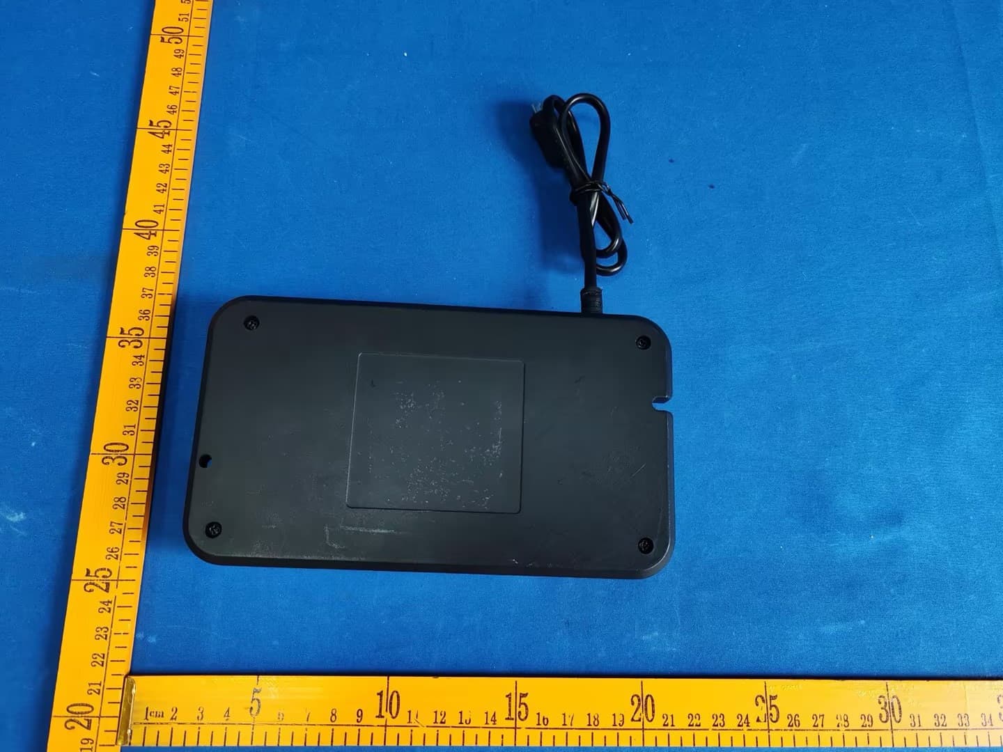
2AOTUKDDYM002B
Sep 22, 2024Control Box
Equipment Class
JAB - Part 15 Class B Digital Device2AOTUKDHM003D
Aug 11, 2024Handset
Equipment Class
DSC - Part 15 Security/Remote Control Transmitter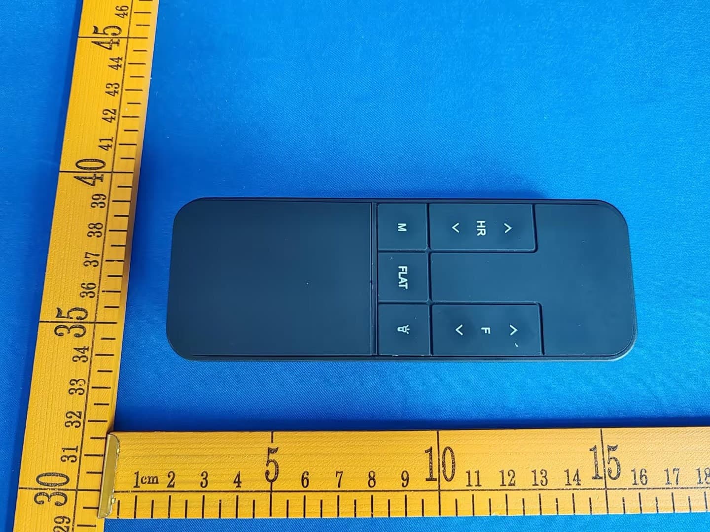
2AOTUKDHM003A
Jul 30, 2024Handset
Equipment Class
DXX - Part 15 Low Power Communication Device Transmitter2AOTUKDWLC1015A
Mar 27, 2024Wireless Charger
Equipment Class
DCD - Part 15 Low Power Transmitter Below 1705 kHz