2AOUZNTG7QHIGLF2Automotive head unit to be installed in cars with the following features FM, AM, DAB, USB, Bluetooth, WLAN and GNSS
Continental Automotive Technologies GmbH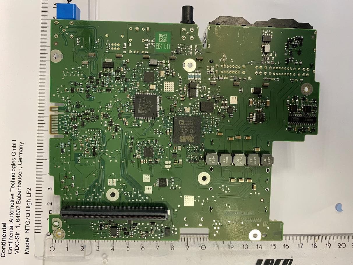
Click to zoom
Application Details
- Equipment Class
- DSS - Part 15 Spread Spectrum Transmitter
- Date of Grant
- Jan 19, 2023
- Application Purpose
- Original Equipment
- Date of Application
- Jan 19, 2023
- Equipment Note
- Automotive head unit to be installed in cars with the following features FM, AM, DAB, USB, Bluetooth, WLAN and GNSS
- Frequency Range
- 2402.00000000 - 2480.00000000
- Country
- Germany
Documents & Files
Document Text
Text extracted from the exhibit documents filed with the FCC. Open a document above to read the original.
Users Manual
S-Class Owner's Manual Mercedes-Benz Front passenger airbag warning & WARNING Risk of injury or fatal injuries if the front passenger airbag is enabled If the front passenger airbag is enabled, a child on the front passenger seat may be struck by the front passenger airbag during an accident. NEVER use a rearward facing child restraint system on a seat protected by an ENABLED FRONT AIRBAG in front of it, this can result in DEATH or SERIOUS INJURY to the child. Observe the chapter "Children in the vehicle". Thank you for purchasing a Mercedes-Benz Before you first drive off, read this Owner's Man‐ ual carefully and familiarise yourself with your vehicle. For your own safety and a longer operat‐ ing lifespan of the vehicle, follow the instructions and warning notices in this Owner's Manual. Dis‐ regarding them may lead to damage to the vehi‐ cle or injury to people. The standard equipment and product description of your vehicle may vary and depends on the fol‐ lowing factors: R model R order R national version R availability The illustrations in this Owner's Manual show a left-hand drive vehicle. On right-hand-drive vehi‐ cles, the layout of car parts and control ele‐ ments differs accordingly. Mercedes-Benz is constantly developing its vehi‐ cles further. Mercedes-Benz therefore reserves the right to introduce changes in the following areas: R design R equipment R technical features The equipment in your vehicle may therefore dif‐ fer from that shown in the descriptions and illus‐ trations. The following documents are integral parts of the vehicle: R printed Owner's Manual R service booklet R equipment-dependent Supplements Keep these documents in the vehicle at all times. If you sell the vehicle, always pass all of the documents on to the new owner. ohne ohne Symbols ........................................................5 At a glance ....................................................6 Cockpit ........................................................... 6 Indicator and warning lamps ........................... 8 Overhead control panel ................................ 10 Door control panel and seat adjustment ....... 12 Control settings in the rear passenger compartment ................................................ 14 Emergencies and breakdowns ...................... 16 Digital Owner's Manual .............................18 Calling up the Digital Owner's Manual .......... 18 General notes .............................................20 Protection of the environment ...................... 20 Take-back of end-of-life vehicles ................... 20 Mercedes-Benz GenuineParts ....................... 21 Owner's Manual ........................................... 22 Touch-sensitive controls ............................... 22 Operating safety ........................................... 22 Declaration of Conformity ............................. 24 Diagnostics connection ................................ 29 Qualified specialist workshop ....................... 30 Vehicle registration ....................................... 30 Correct use of the vehicle ............................. 31 Information on the REACH regulation ........... 31 Notes for persons with electronic medi‐ cal aids ......................................................... 31 Implied warranty ........................................... 31 QR code for rescue card ............................... 32 Data storage ................................................. 32 Copyright ...................................................... 34 Occupant safety .........................................35 Restraint system ........................................... 35 Seat belts ..................................................... 37 Airbags ......................................................... 42 PRE-SAFE ® system ....................................... 49 Automatic measures after an accident ......... 51 Safely transporting children in the vehi‐ cle ................................................................. 51 Notes on pets in the vehicle ......................... 65 Opening and closing ..................................67 Key ................................................................ 67 Doors ............................................................ 71 Boot .............................................................. 76 Side windows ............................................... 82 Sliding sunroof ............................................. 86 Roller sunblinds ............................................ 91 Anti-theft protection ..................................... 93 Seats and stowing .....................................96 Notes on the correct driver's seat posi‐ tion ............................................................... 96 Seats ............................................................ 96 Steering wheel ............................................. 111 Easy entry and exit feature .......................... 112 Operating the memory function .................. 114 Memory function in the rear compart‐ ment ........................................................... 116 Stowage areas ............................................. 119 Cup holders ................................................ 130 Ashtray and cigarette lighter ....................... 131 Sockets ....................................................... 133 Coolbox ...................................................... 136 Wireless charging of the mobile phone and connection with the exterior aerial ...... 138 Fitting and removing the floor mats ............ 141 2 Contents Light and sight .........................................143 Exterior lighting .......................................... 143 Interior lighting ............................................ 151 Windscreen wipers and windscreen washer system ............................................ 152 Mirrors ........................................................ 156 Area permeable to…
Text truncated - open the document above for the full version.
Users Manual
HANDS-FREE ACCESS function With HANDS-FREE ACCESS you can open, close or interrupt boot lid movement by performing a kicking movement under the rear bumper. The kicking movement triggers the opening or closing process alternately. Observe the notes when opening (/ page 76) and closing (/ page 77) the boot lid. % A warning tone sounds while the boot lid is opening or closing. & WARNING Risk of burns caused by a hot exhaust system The vehicle exhaust system can become very hot. If you use HANDS-FREE ACCESS, you could burn yourself by touching the exhaust system. # Always ensure that you only make a kicking movement within the detection range of the sensors. * NOTE Damage to the vehicle caused by unintentionally opening the boot lid: R when using an automatic car wash R when using a high pressure cleaner # Deactivate KEYLESS-GO or make sure that the key located is at least 3 m away from the vehicle in such situa‐ tions. When making the kicking movement, make sure that your feet are firmly on the ground, other‐ wise you could lose your balance, e.g. on ice. Observe the following notes: R The key is behind the vehicle. R Stand at least 30 cm away from the vehicle while performing the kicking movement. R Do not come into contact with the bumper while making the kicking movement. R Do not carry out the kicking movement too slowly. R The kicking movement must be towards the vehicle and back again. 80 Opening and closing 1 Detection range of the sensors If several consecutive kicking movements are not successful, wait ten seconds. System limits The system may be impaired or may not function in the following cases: R The area around the sensor is dirty, e.g. due to road salt or snow. R The kicking movement is made using a pros‐ thetic leg. The boot lid could be opened or closed uninten‐ tionally, in the following situations: R If a person's arms or legs are moving in the sensor detection range, e.g. when polishing the vehicle or picking up objects. R If objects are moved or placed behind the vehicle, e.g. tensioning straps or luggage. R If clamping straps, tarpaulins or other cover‐ ings are pulled over the bumper. R If a protective mat with a length reaching over the boot sill down into the detection range of the sensors is used. R If the protective mat is not secured correctly. R When working on the trailer coupling, trailers or rear bicycle racks. Deactivate KEYLESS-GO (/ page 68) or do not carry the key about your person in such situa‐ tions. Switching separate boot locking on and off Multimedia system: 4 © 5 Settings 5 Vehicle 5 Locking function Switching separate boot locking on # Select Block boot. # Create a PIN. # Press OK to confirm the PIN. # Enter the PIN again and confirm it. The boot will remain locked if you unlock the vehicle centrally. % If an accident has been detected, the boot will unlock even if separate locking is switched on. % You can open the boot with the emergency key even while boot locking is active. Sepa‐ rate boot locking will remain active. Switching separate boot locking off # Select Block boot. Opening and closing 81 # Enter the PIN. If the PIN is correct, separate boot locking will be switched off and the PIN deleted. Resetting the PIN If you have forgotten the PIN, you can switch off separate boot locking with the emergency key. # Select Block boot. # Confirm Forgotten PIN?. # Unlock the boot within 30 seconds with the emergency key. Separate boot locking will be switched off and the PIN deleted. Unlocking the boot lid using the emergency key # Take the emergency key element out of the key (/ page 69). # Insert the emergency key into the boot lock as far as it will go. # Turn the emergency key anti-clockwise from position 1 to position 2. # Turn the emergency key back to position 1 and remove it. % If you use the emergency key to unlock and open the boot lid, the anti-theft alarm sys‐ tem will be triggered. Activating/deactivating the boot lid opening limiter Multimedia system: 4 © 5 Settings 5 Vehicle 5 Other functions # Activate or deactivate Opening height limiter. This function allows you to avoid bumping the boot lid on a low garage ceiling, for example. Side windows Opens and closes the side windows & WARNING Risk of becoming trapped when opening a side window When you open a side window, parts of the body could be drawn in or become trapped between the side window and window frame. # When opening, make sure that nobody is touching the side window. 82 Opening and closing # If someone is trapped, release the but‐ ton immediately or pull it in order to close the side window again. & WARNING Risk of becoming trapped when closing a side window When closing a side window, body parts could be trapped in the closing area in the process. # When closing, make sure that no body parts are in the closing area. # If someone is trapped, release the but‐ ton immediately or press the button in order to reopen the side window. & WARNING Risk of becoming trapped when children operate the side windows Children could become trapped if they oper‐ ate the side windows, particularly when unat‐ tended. # Activate the child safety lock for the rear side windows. # When leaving the vehicle, always take the key with you and lock the vehicle. # Never leave children unattended in the vehicle. Requirements: R The power supply or the ignition is switched on. 1 Closing 2 Opening The buttons on the driver's door take prece‐ dence. # To start automatic operation: press the W button beyond the point of resistance or pull and release it. Opening and closing 83 # To interrupt automatic operation: press or pull the W button again. When the vehicle is switched off, the side win‐ dows can continue being operated. This function is available for around four minutes or until a front door is opened. % Vehicles with electric roller sunblinds on rear doors on the left and right: the but‐ tons for the rear side windows also open and close the roller sunblinds (/ page 91). Automatic reversing function o…
Text truncated - open the document above for the full version.
Users Manual
Maintenance display # Remove protective film 1 from the mainte‐ nance display on the tip of the newly fitted wiper blades. When the colour of the maintenance display changes from black to yellow, the wiper blades should be replaced. % The duration until the colour changes varies depending on the usage conditions. Replacing the windscreen wiper blades (MAGIC VISION CONTROL) Moving the wiper arms into the replacement position # Switch the ignition off. # Within around 15 seconds, press the î button on the combination switch (/ page 152). The wiper arms will move into the replace‐ ment position. Removing the wiper blades # To bring the wiper blade into position to be removed: hold the wiper arm firmly in one hand. With the other hand, turn the wiper blade in the direction of arrow 1 beyond the point of resistance. The wiper blade will engage in the removal position with a click. Light and sight 155 # To remove the wiper blade: press release knob 2, pull the wiper blade in the direction of arrow 3 and remove. Fitting the wiper blades # Push the new wiper blade onto the wiper arm in the direction of arrow 1 until release knob 2 engages. # Press the wiper blade onto the wiper arm in the direction of arrow 3 beyond the point of resistance. The wiper blade will engage with a noticeable click and move freely again. # Fold the wiper arm back onto the wind‐ screen. Mirrors Operating the outside mirrors & WARNING Risk of accident due to adjusting vehicle settings while the vehi‐ cle is in motion You could lose control of the vehicle in the following situations in particular: R If you adjust the driver's seat, the head restraints, the steering wheel or the mir‐ ror while the vehicle is in motion. R If you fasten your seat belt while the vehi‐ cle is in motion. # Before starting the engine: adjust the driver's seat, the head restraints, the steering wheel and the mirror and fas‐ ten your seat belt. & WARNING Risk of accident due to mis‐ judgement of distance when using the outside mirror The outside mirrors reflect objects on a smaller scale. The objects in view are in fact closer than they appear. # Therefore, always look over your shoul‐ der in order to ensure that you are aware of the actual distance between you and the road users driving behind you. 156 Light and sight Folding the outside mirrors in/out # Briefly press button 3. Resetting the outside mirrors % If the battery has been disconnected or com‐ pletely discharged, the outside mirrors must be reset. Only then will the automatic mirror folding function work properly. # Briefly press button 3. Adjusting the outside mirrors # Select the required mirror using button 2 or 4. % In vehicles with MBUX Interior Assistant, the required outside mirror can also be preselec‐ ted automatically via a natural head move‐ ment to the left or right (/ page 317). # Use button 1 to set the position of the mir‐ ror you have selected. Engaging the outside mirrors # Press and hold button 3. You will hear a click and the mirror will audi‐ bly click into place. The mirror will now be set to the correct position. Automatic anti-dazzle mirrors function & WARNING Risk of acid burns and poi‐ soning due to the anti-dazzle mirror elec‐ trolyte Electrolyte may escape if the glass in an automatic anti-dazzle mirror breaks. The electrolyte is hazardous to health and causes irritation. It must not come into con‐ tact with your skin, eyes, respiratory organs or clothing or be swallowed. # If you come into contact with electro‐ lyte, observe the following: R Immediately rinse the electrolyte from your skin with water and seek medical attention. R If electrolyte comes into contact with your eyes, immediately rinse them thoroughly with clean water and seek medical attention. R If the electrolyte is swallowed, immediately rinse your mouth out thoroughly. Do not induce vomiting. Seek medical attention immediately. R Immediately change out of clothing which has been contaminated with electrolyte. R If an allergic reaction occurs, seek medical attention immediately. Light and sight 157 The inside rearview mirror and the outside mir‐ ror on the driver's side will automatically go into anti-dazzle mode if light from a headlamp hits the sensor on the inside rearview mirror. System limits The system will not go into anti-dazzle mode if: R the engine is switched off. R reverse gear is engaged. R the interior lighting is switched on. Front-passenger outside mirror parking posi‐ tion function The parking position makes parking easier. The front-passenger outside mirror will swivel downwards in the direction of the rear wheel on the front passenger's side when: R the parking position is stored (/ page 158). R the front-passenger mirror is selected. R reverse gear is engaged. The front-passenger outside mirror will move back to its original position when: R you shift the transmission to another trans‐ mission position. R you are travelling at a speed greater than 15 km/h. R you press the button for the outside mirror on the driver's side. Storing the parking position of the front- passenger outside mirror using reverse gear Storing # Select the front-passenger outside mirror using button 2. # Engage reverse gear. # Move the front-passenger outside mirror into the desired parking position using button 1. 158 Light and sight Calling up # Select the front-passenger outside mirror using button 2. # Engage reverse gear. The front-passenger outside mirror will move into the stored parking position. Activating/deactivating the automatic mirror folding function Multimedia system: 4 © 5 Settings 5 Vehicle 5 Locking function 5 Automatic fold-in # Activate or deactivate the function. Area permeable to radio waves on the windscreen Radio-controlled equipment, such as toll sys‐ tems, can be mounted only on areas 1 of the windscreen that are permeable to radio waves. Areas permeable to radio waves 1 are best visi‐ ble from outside the vehicle when the wind‐ screen is illuminated with an external light so…
Text truncated - open the document above for the full version.
Users Manual
6 Engine oil temperature 7 Engine speed Displays 1, 2, 4, 5 and 6 can be shown/ hidden. The following functions are available on the Options submenu: R Set display content as the standard dis‐ play(/ page 275) Calling up displays on the Trip menu On-board computer: 4 Trip You can show/hide different display content on the Trip menu. # Swipe upwards or downwards on the left- hand Touch Control. 1 Driving timeFrom reset 2 Driving timeFrom start 3 Average fuel consumptionFrom start 4 Distance to the destination; estimated arrival time 5 Fuel range 6 AdBlue ® range 7 Distance to the traffic incident; estimated travel time gained or lost due to the traffic incident 8 Total distanceFrom start 9 Total distanceFrom reset A Average fuel consumptionFrom reset % Displays 4, 5, 6 and 7 are displayed in a situation-specific manner. The following functions are available on the Options submenu: R Set display content as the standard display (/ page 275) R Reset From start and From reset values Calling up navigation instructions on the on- board computer On-board computer: 4 Navigation The following map views are available on the Navigation menu: R Whole map R 2D direction of travel R 2D north orientation R 3D map % The level of detail in the navigation instruc‐ tions on the left-hand display range may vary. 280 Instrument Display and on-board computer 1 Distance to the change of direction 2 Road to which the change of direction leads 3 Display of traffic incident 4 Currently selected route 5 Display of vehicle's current position 6 Change-of-direction symbol 7 Recommended lane (white) 8 Lane not recommended (grey) 9 Current lane You can change the map scale of the selected map view on the Navigation menu. # Swipe upwards or downwards on the left- hand Touch Control. On the Options submenu, you can use other functions in the route and Map settings catego‐ ries. You can use the following functions in the route category: R Cancel current route guidance. R Call up previous destinations and favourites. You can use the following functions in the Map settings category: R Activate auto zoom. R Set the map view, satellite view and route overview. The following functions are available on the Options submenu: R Set display content as the standard display (/ page 275) Selecting the radio or media source using the on-board computer On-board computer: 4 Entertainment The following display content, for example, can be displayed on the Entertainment menu: R Radio R Media R Browser R ENERGIZING COMFORT Radio on the Entertainment menu (example) 1 Previous radio station or previous track 2 Frequency range or media source 3 Radio station or current track 4 Name of track and artist 5 Next radio station or next track Instrument Display and on-board computer 281 # To select the radio or media on the enter‐ tainment menu: press the left-hand Touch Control. The Options submenu will be displayed. # Select the Radio or Media menu item by swiping upwards or downwards on the left- hand Touch Control and confirm by pressing the left-hand Touch Control. Changing radio station or track in an active media source # To select a radio station: swipe upwards or downwards on the left-hand Touch Control. % When you select a saved radio station in the frequency range, a star ß will appear next to the radio station name. # To change tracks in an active media source: swipe left or right on the left-hand Touch Control. % This is how to select the channel for the TV media source. Changing the frequency band on the Options submenu # Select the Radio menu item by swiping upwards or downwards on the left-hand Touch Control and confirm by pressing the left-hand Touch Control. # Swipe left or right on the left-hand Touch Control and select a frequency band by pressing the left-hand Touch Control. Selecting a media source on the Options submenu # Select the Media menu item by swiping upwards or downwards on the left-hand Touch Control and confirm by pressing the left-hand Touch Control. # Swipe upwards or downwards on the left- hand Touch Control and select a media source by pressing the left-hand Touch Con‐ trol. The following additional function is available on the Options submenu: R Set display content as the standard dis‐ play(/ page 275) Configuring displays on the individual menu On-board computer: 4 Individual Up to five different types of display content can be displayed on the Individual menu. # To expand the display content: swipe upwards on the left-hand Touch Control. # To reduce the display content: swipe downwards on the left-hand Touch Control. The display content is also individually adjusta‐ ble. # To call up the Options submenu: press the left-hand Touch Control. # To configure the display content of the individual menu: confirm the Change indi- vidual request by pressing the left-hand Touch Control. The corresponding menu for the configura‐ tion of the display content will open in the multimedia system. The respective display content of the Individual menu is configured within the multimedia sys‐ 282 Instrument Display and on-board computer tem. As soon as you confirm the configuration in the multimedia system or by pressing the left- hand back button on the multifunction steering wheel, the message Configuration completed will appear on the instrument cluster. Display content selection, left and right: R Standard display R Traffic incidents R Range R Navigation R Consumption R Audio R Weather R Trip computer From start and From reset R ECO display Display content selection, centre: R G-meter R ECO display R Navigation R Rev counter R Speedometer R ATTENTION ASSIST display The following setting options are available on the Options submenu depending on the selected dis‐ play content: R Set display content as the standard dis‐ play(/ page 275) R Reset From start values R Reset From reset values R Reset Trip meter R Set a route R Change track or media source % Please note that not all areas for display con‐ tent shown have to be configur…
Text truncated - open the document above for the full version.
Users Manual
Removing the fire extinguisher * NOTE Damage to the stowage compart‐ ment # Keep the stowage compartment closed while the vehicle is moving. # Pull handle 1 up and fold the cover for‐ wards in the direction of the arrow. # Remove the fire extinguisher from the stow‐ age compartment. Flat tyre Notes on flat tyres & WARNING Risk of accident due to a flat tyre A flat tyre severely affects the driving charac‐ teristics as well as the steering and braking of the vehicle. Tyres without run-flat characteristics: # Do not drive with a flat tyre. # Change the flat tyre immediately with an emergency spare wheel or spare wheel. Alternatively, consult a qualified specialist workshop. Tyres with run-flat characteristics: # Observe the information and warning notes on MOExtended tyres (run-flat tyres). In the event of a flat tyre, the following options are available depending on your vehicle's equip‐ ment: R Vehicles with MOExtended tyres: it is pos‐ sible to continue the journey for a short period of time. Make sure you observe the notes on MOExtended tyres (run-flat tyres) (/ page 471). R Vehicles with a TIREFIT kit: you can repair the tyre so that it is possible to continue the journey for a short period of time. To do this, use the TIREFIT kit (/ page 472). R Vehicles with Mercedes me connect: you can make a call for breakdown assistance via the overhead control panel in the case of a breakdown (/ page 400). R All vehicles: change the wheel (/ page 500). 470 Breakdown assistance Notes on MOExtended tyres (run-flat tyres) & WARNING Risk of accident when driving in limp-home mode Driving in emergency mode impairs the han‐ dling characteristics of the vehicle. # Do not exceed the permissible maxi‐ mum speed of the MOExtended tyres. # Avoid any abrupt steering and driving manoeuvres as well as driving over obstacles (kerbs, pot holes, off-road). This applies, in particular, to a loaded vehicle. # Stop driving in the emergency mode if you notice: R banging noise R vehicle vibration R smoke which smells like rubber R continuous ESP ® intervention R cracks in the tyre sidewalls # After driving in emergency mode, have the rims checked by a qualified special‐ ist workshop with regard to their further use. # The defective tyre must be replaced in every case. With MOExtended tyres (run-flat tyres), you can continue to drive your vehicle even if there is a total loss of pressure in one or more tyres. How‐ ever, the tyre affected must not show any clearly visible damage. You can recognise MOExtended tyres by the MOExtended marking which appears on the side wall of the tyre. Vehicles with tyre pressure monitoring sys‐ tem: MOExtended tyres may only be used in conjunction with an activated tyre pressure mon‐ itoring system. If a pressure loss warning message appears in the driver's display, proceed as follows: R Check the tyre for damage. R If driving on, observe the following notes. Driving distance possible in emergency mode after the pressure loss warning: Load conditionDriving distance pos‐ sible in emergency mode Partially laden80 km Fully laden30 km The driving distance possible in emergency mode may vary depending on the driving style. Observe the maximum permissible speed of 80 km/h. If a tyre has gone flat and cannot be replaced with an MOExtended tyre, you can use a stand‐ ard tyre as a temporary measure. TIREFIT kit storage location Depending on the vehicle's equipment, the stor‐ age bag for the TIREFIT kit is located in the lug‐ gage compartment or on the left side of the stowage net. Comply with the loading guidelines (/ page 119). Breakdown assistance 471 % You can find information on the power cate‐ gory (LK) and/or electrical data on the back of the tyre inflation compressor: R LK2 – 12 V/15 A, 180 W, 0.8 kg At a distance of approximately 1 m to the tyre inflation compressor and approximately 1.6 m above the ground, the following sound pressure levels apply: R Emissions sound pressure level L PA 83 dB (A) R Sound power level L WA 91 dB (A) The tyre inflation compressor is mainte‐ nance-free. If there is a malfunction, please contact a qualified specialist workshop. Using the TIREFIT kit Requirements: R Tyre sealant bottle and tyre inflation com‐ pressor (/ page 471). R TIREFIT sticker R Gloves (depending on the vehicle equipment) You can use TIREFIT tyre sealant to seal perfora‐ tion damage of up to 4 mm, particularly those in the tyre contact surface. You can use TIREFIT in outside temperatures down to -20 °C. & WARNING Risk of accident when using tyre sealant The tyre sealant may be unable to seal the tyre properly, especially in the following cases: R there are cuts or punctures in the tyre larger than damage previously men‐ tioned. R the wheel rim is damaged. R you have driven at very low tyre pres‐ sures or on a flat tyre. # Do not drive on. # Consult a qualified specialist workshop. & WARNING Risk of injury and poisoning from tyre sealant Tyre sealant is hazardous to health and cau‐ ses irritation. Do not allow it to come into contact with your skin, eyes or clothing, and do not swallow it. Do not inhale any vapours. Keep the tyre sealant away from children. Observe the following if you come into con‐ tact with the tyre sealant: # Rinse off the tyre sealant from your skin using water immediately. # If tyre sealant gets into your eyes, thor‐ oughly rinse them using clean water immediately. # If tyre sealant has been swallowed, thoroughly rinse out your mouth imme‐ diately and drink plenty of water. Do not induce vomiting and seek medical attention immediately. # Change out of clothing which has come into contact with tyre sealant immedi‐ ately. 472 Breakdown assistance # If an allergic reaction occurs, seek med‐ ical attention immediately. * NOTE Overheating due to the tyre infla‐ tion compressor running too long # Do not run the tyre inflation compres‐ sor for longer than ten minutes without interruption. Comply with the manufacturer's safety notes on the sticker on the tyre inflation compr…
Text truncated - open the document above for the full version.
Contact Information
Applicant
Bettina Christ(Team Lead RF Homologation)
Technical Contact
DEKRA Testing and Certification S.A.U.Eduardo Pavia Rubio
[email protected]3495269125
Calle Severo Ochoa 2, Parque Tecnologico Andalucia · Malaga · Spain
Test Firm
DEKRA Testing and Certification, S.A.U.Rafael Lopez Martin
Technical Specifications
| # | Rule Parts | Frequency Range | Power Output |
|---|---|---|---|
| 1 | 15C | 2.40 GHz - 2.48 GHz | 14.79 mW |
Other Applications from Continental Automotive Technologies GmbH
2AOUZ-23040401
Sep 24, 2023VW instrument cluster
Equipment Class
DCD - Part 15 Low Power Transmitter Below 1705 kHz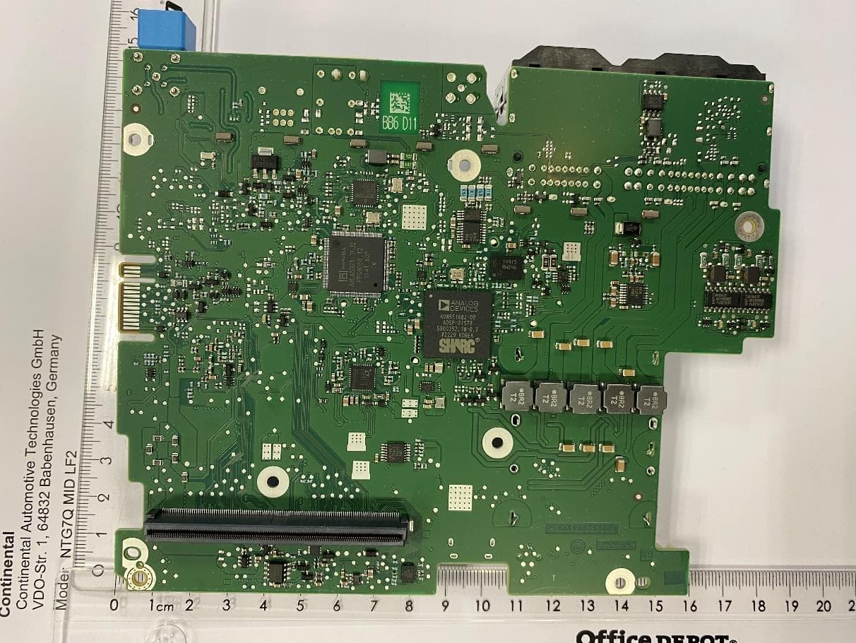
2AOUZNTG7QMIDLF2
Jan 22, 2023Automotive head unit to be installed in cars with the following features FM, AM, DAB, USB, Bluetooth, WLAN and GNSS
Equipment Class
DTS - Digital Transmission System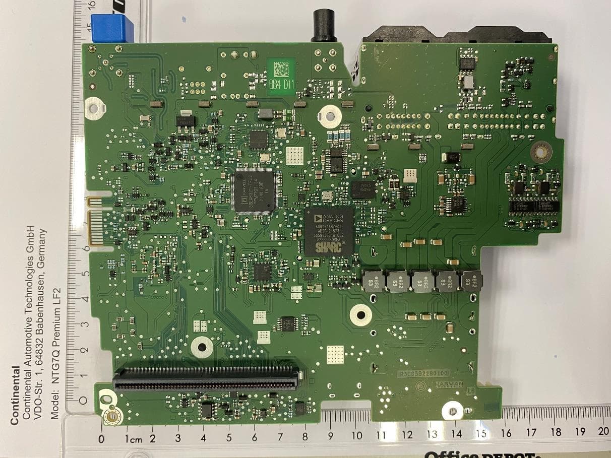
2AOUZNTG7QPRELF2
Jan 22, 2023Automotive head unit to be installed in cars with the following features FM, AM, DAB, USB, Bluetooth, WLAN and GNSS
Equipment Class
DSS - Part 15 Spread Spectrum Transmitter
2AOUZNTG7PRELFT2
Oct 01, 2020Automotive head unit to be installed in cars with the following features FM AM DAB USB Bluetooth WLAN and GNSS
Equipment Class
DSS - Part 15 Spread Spectrum Transmitter
2AOUZNTG7PRPLFT2
Oct 01, 2020Automotive head unit to be installed in cars with the following features FM AM DAB USB Bluetooth WLAN and GNSS
Equipment Class
DSS - Part 15 Spread Spectrum Transmitter