2AOW4-KTX900USB900MHz Transceiver with USB interface
CM GLOBAL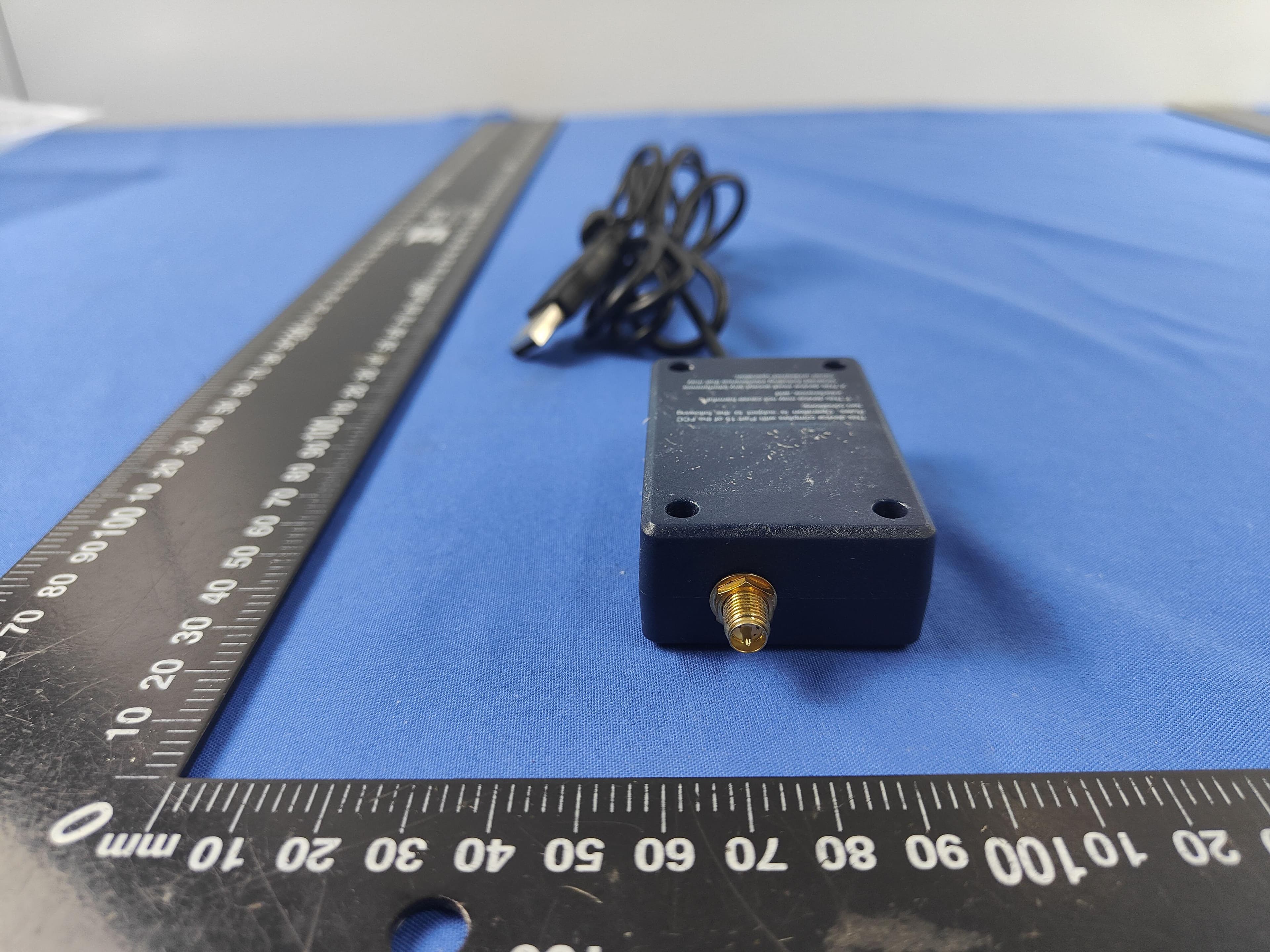
Click to zoom
Application Details
- Equipment Class
- DXX - Part 15 Low Power Communication Device Transmitter
- Date of Grant
- Aug 13, 2022
- Application Purpose
- Original Equipment
- Date of Application
- Aug 13, 2022
- Equipment Note
- 900MHz Transceiver with USB interface
- Frequency Range
- 903.12500000 - 910.12500000
- Company
- CM GLOBAL
- Country
- United States
Documents & Files
Document Text
Text extracted from the exhibit documents filed with the FCC. Open a document above to read the original.
Users Manual
KTX900 Wireless Transceivers User Guild KTX900-UART KTX900-USB Figure 1. Wireless transceivers Features: 1. Providing USB and UART interface, highly integrated wireless transceiver can be connected with equipment directly for establish wireless communication linkage. 2. Low RF power transmission: Maximum transmit RF Power 50mW. 3. GFSK/FSK modulation mode. 4. Crystal frequency stabilization. 5. High-efficiency forward error correction channel encoding technology is used. Main Applications: 1. AMR – Automatic Meter Reading 2. Wireless alarm and security system 3. Wireless POS and PDA 4. Long-distance non-contact RF smart card, RFID tags 5. Wireless Field Bus, Wireless conference voting system 6. Remote control of industrial equipment 7. Industrial telemetry Technical Specifications: RF Channels (MHz) 903.125, 904.125, 906.125, 907.125 908.125, 908.125, 909.125, 910.125 Transmission Power 7dBm, 10dBm, 14dBm, 17dBm Modulation Mode GFSK Baud Rate 9600bps Interface Data Format USB, UART ,8E1/8N1 data format Power Supply DC 3.6V---5V Overall Dimensions USB: 60 X 42 X 21 mm UART: 59 X 47 X 10 mm Physical Dimension: KTX900-UART KTX900-USB Figure 2. Interface and Size Interface Description: KTX900 wireless transceiver can be directly connected with equipment by interface port show as Figure 3 and Figure 4. KTX900-UART can be directly connected to equipment’s UART port UART Interface Connector P1 1234 5 UART Signal Name VCCRXDTXDAUX GND Figure 3 KTX900-USB can be directly connected to equipment’s USB port USB Interface Connector P1 1234 USB Interface Signal Name VbusD-D+GND Figure 4 Options: Referring to Figure 3, KTX900 transceivers have the options as listed in Table 1 and Table 2 below: Options for KTX900-UART Remark With Power and Active Indicator Populate components R1, R2, PWR, ACTIVE Channel setting DIP switch –Top access Populate DIP switch on S1-A Channel setting DIP switch –Side access Populate DIP switch on S1-B Channel setting DIP switch –Rear access Populate DIP switch on S1-C DIP package RF module Install DIP package RF module on E31 SMT package RF moduleInstall SMT package RF module on S3 Table 1 Options for KTX900-USB Remark With Power and Active Indicator Populate R1, R2, PWR, ACTIVE DIP package RF module Install DIP package RF module on E2 SMT package RF moduleInstall SMT package RF module on E1 Table 2 Frequency Channel Setting There is a channel setting switch as shown in Figure 5 , defined as A1, A2, A3, A4 and A5 respectively, where A1~A3 is for channel setting and A4~A5 is for RF transmission Power Setting. Switch Channel A1 A2 A3 Frequency A4 A5RF Power 1 0 0 0 903.125Mhz 0022dBm 2 1 0 0 904.125Mhz 1017dBm 3 0 1 0 905.125Mhz 0113dBm 4 1 1 0 906.125Mhz 1110dBm 5 0 0 1 907.125Mhz 6 1 0 1 908.125Mhz 7 0 1 1 909.125Mhz 8 1 1 1 910.125Mhz Highlighted is default setting Communication Application: Figure 4. KTX900 Wireless Communication Application Diagram FCC Notices 1. The manufacturer is not responsible for any radio or TV Interference caused by unauthorized modifications to this equipment. Such modifications could void the user’s authority to operate the equipment. 2. This device complies with Part 15 of the FCC Rules. (1) This device may not cause harmful interference, and (2) this device must accept any interference received, including interference that may cause undesired operation. NOTE: This equipment has been tested and found to comply with the limits for a Class B digital device, pursuant to part 15 of the FCC Rules. These limits are designed to provide reasonable protection against harmful interference in a residential installation. This equipment generates, uses and can radiate radio frequency energy and, if not installed and used in accordance with the instructions, may cause harmful interference to radio communications. However, there is no guarantee that interference will not occur in a particular installation. If this equipment does cause harmful interference to radio or television reception, which can be determined by turning the equipment off and on, the user is encouraged to try to correct the interference by one or more of the following measures: —Reorient or relocate the receiving antenna. —Increase the separation between the equipment and receiver. —Connect the equipment into an outlet on a circuit different from that to which the receiver is connected. —Consult the dealer or an experienced radio/TV technician for help. This equipment complies with FCC RF radiation exposure limits set forth for an uncontrolled environment. This equipment should be installed and operated with a minimum distance of 20 centimeters between the radiator and your body.
Cover Letter(s)
CMGLOBAL 1201N.4THSTREET,WATERTOWN,WI53098,USA AgentAuthorization Company:CMGLOBAL Address:1201N.4THSTREET,WATERTOWN,WI53098,USA ProductName:900MHzTransceiverwithUSBinterface ModelNumber(s):KTX900,KTX900-USB ProductDescription:900MHzTransceiverwithUSBinterface WeauthorizeMiCOMLabsInc.,575BoulderCourt,Pleasanton,California94566,USA, toactonourbehalfonallmattersconcerningthecertificationofabovenamed equipment. WedeclarethatMiCOMLabsInc.isallowedtoforwardallinformationrelatedtothe approvalandcertificationofequipmenttotheregulatoryagenciesasrequiredandto discussanyissuesconcerningtheapprovalapplication.Anyandallactscarriedoutby MiCOMLabsonourbehalfshallhavethesameeffectasactsofourown. Signature:Date:Aug.03,2022 Name:LISAMSMALL Title:Manager Company:CMGLOBAL
Cover Letter(s)
CMGLOBAL 1201N.4THSTREET,WATERTOWN,WI53098,USA OfficeofEngineeringTechnology FederalCommunicationsCommission 7435OaklandMillsRoad Columbia,MD21046 USA Date:2022/08/03 Subject;RequestforConfidentiality FCCID:2AOW4-KTX900USB ToWhomItMayConcern, PursuanttotheprovisionsoftheCommission’srulesTitle47Sections§0.457and§0.459,we arerequestingtheCommissiontowithholdthefollowingattachment(s)asconfidential documentsfrompublicdisclosureindefinitely. Thesedocumentscontaindetailedsystemandequipmentdescriptionsandareconsideredas proprietaryinformationinoperationoftheequipment.Thepublicdisclosureofthesedocuments mightbeharmfultoourcompanyandwouldgivecompetitorsanunfairadvantageinthemarket. SchematicDiagram BlockDiagram PartsList OperationalDescription Tune-upProcedure Inadditionaltoabovementioneddocuments,inordertocomplywiththemarketingregulations inTitle47CFR§2.803andtheimportationrulesinTitle47CFR§2.1204,whileensuringthat businesssensitiveinformationremainsconfidentialuntiltheactualmarketingofnewly authorizeddevices,werequestShortTermConfidentialityofthefollowingattachment(s); ExternalPhotos TestSetupPhotos InternalPhotos UserManual For45days,pursuanttoPublicNoticeDA04-1705. OR For180dayspursuanttoKDB726920D01. Itisourunderstandingthatallmeasurementtestreports,FCCIDlabelformatand correspondenceduringthecertificationreviewprocesscannotbegrantedasconfidential documentsandthisinformationwillbeavailableforpublicreviewoncethegrantofequipment authorizationisissued. Sincerely, Signature: Name:LISAMSMALLTitle:Manager
Cover Letter(s)
CMGLOBAL 1201N.4THSTREET,WATERTOWN,WI53098,USA SeriesModelsDescription FCCID:2AOW4-KTX900USBDate:Aug.03,2022 FederalCommunicationsCommission AuthorizationandEvaluationDivision 7435OaklandMillsRoad Columbia,MD21046 Towhomitmayconcern: Thedevice(ProductName:900MHzTransceiverwithUSBinterface)Models Name:KTX900,KTX900-USBhavesameelectrical,PCBandBOM,onlythecolour andmodel’snamesaredifferentformarketingrequirements. Sincerely, LISAMSMALL/Manager
External Photos
FCCID:2AOW4-KTX900USBPage 1 of 3 ReportNo.:CTL2206162073-WF ExternalPhotosofEUT Antenna FCCID:2AOW4-KTX900USBPage 2 of 3 ReportNo.:CTL2206162073-WF FCCID:2AOW4-KTX900USBPage 3 of 3 ReportNo.:CTL2206162073-WF
ID Label/Location Info
FCCID:2AOW4-KTX900USBPage 1 of 1 ReportNo.:CTL2206162073-WF FCCIDLabelInformation Labellocation: Size:45mm*33mm 900MHzTransceiverwithUSBinterface Model:KTX900 FCCID:2AOW4-KTX900USB
Internal Photos
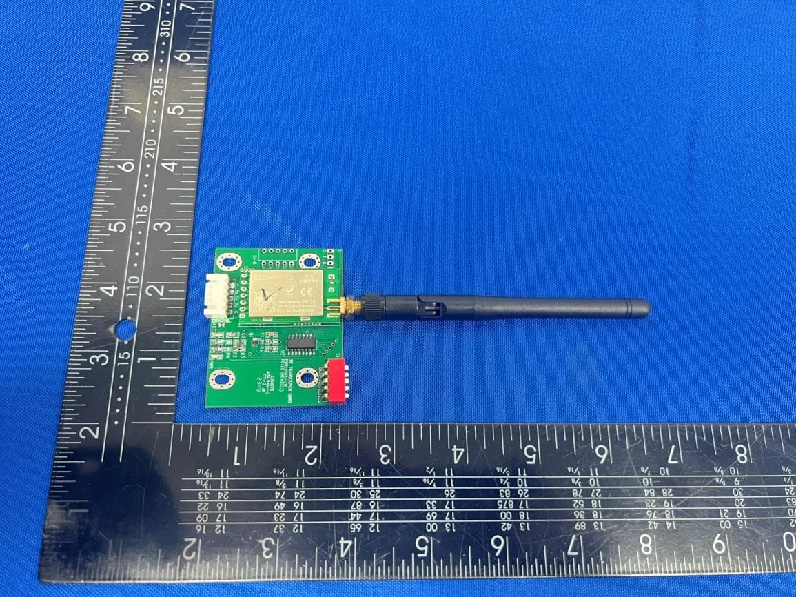
FCCID:2AOW4-KTX900USBPage 1 of 2 ReportNo.:CTL2206162073-WF InternalPhotosofEUT FCCID:2AOW4-KTX900USBPage 2 of 2 ReportNo.:CTL2206162073-WF
Test Setup Photos
FCCID:2AOW4-KTX900USBPage 1 of 1 ReportNo.:CTL2206162073-WF TestSetupPhotosoftheEUT
Contact Information
Applicant
LISA M SMALL
Technical Contact
Test Firm
Shenzhen CTL Testing Technology Co., Ltd.Tracy Qi
[email protected]86-755-89486194
Technical Specifications
| # | Rule Parts | Frequency Range | Power Output |
|---|---|---|---|
| 1 | 15C | 903.125 MHz - 910.125 MHz | - |
Other Applications from CM GLOBAL
2AOW4-KTX433
Apr 06, 2024433MHz Transceiver with UART interface
Equipment Class
DSC - Part 15 Security/Remote Control Transmitter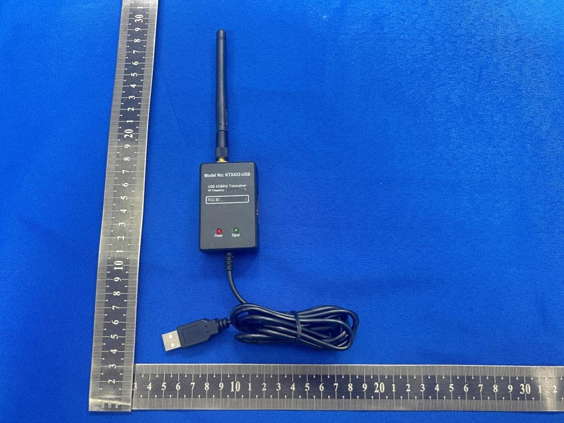
2AOW4-KTX433-USB
Apr 06, 2024433MHz Transceiver with USB/RS232C interface
Equipment Class
DSC - Part 15 Security/Remote Control Transmitter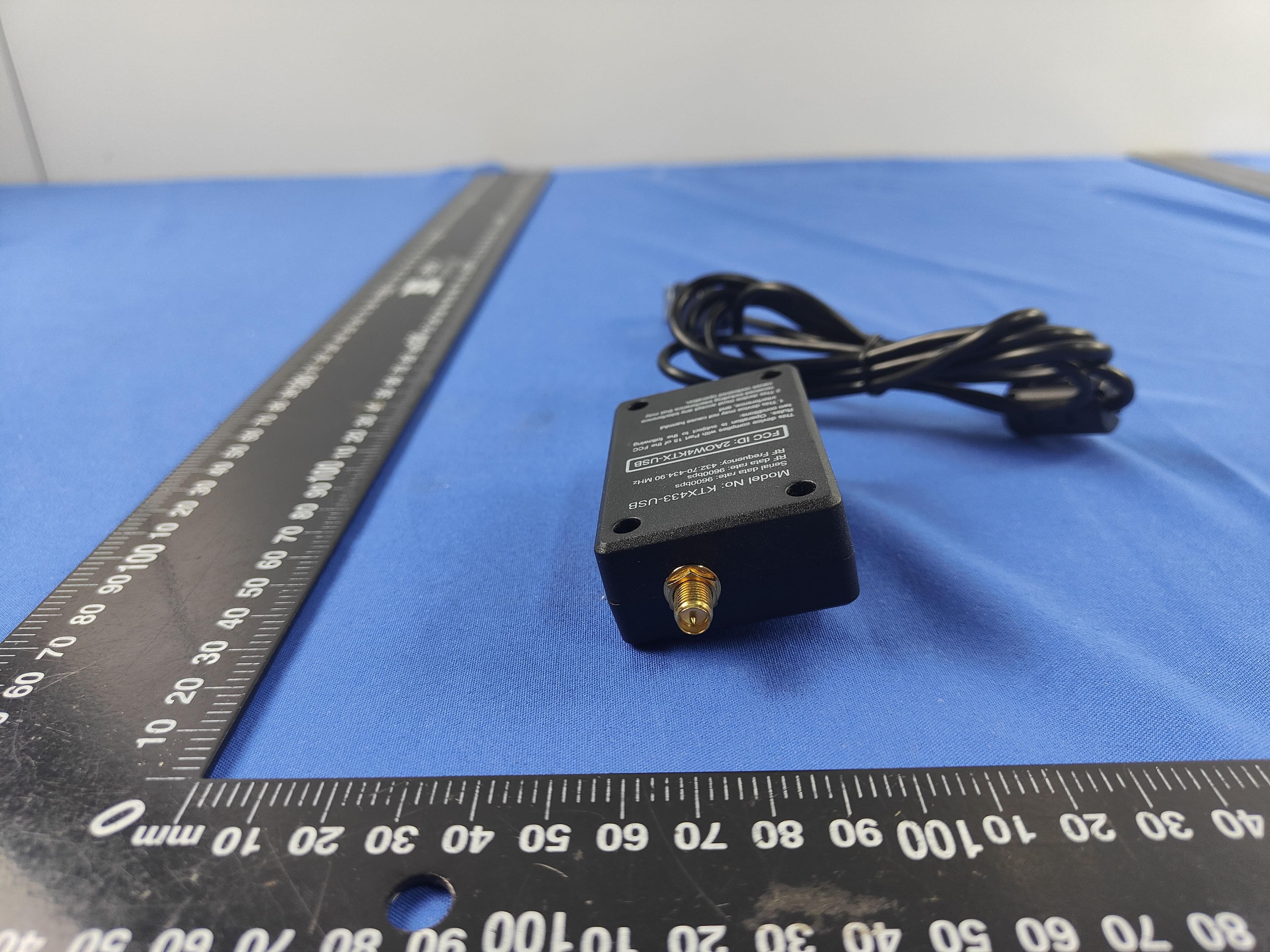
2AOW4-433USB
Aug 15, 2022433MHz Transceiver with USB interface
Equipment Class
DSC - Part 15 Security/Remote Control Transmitter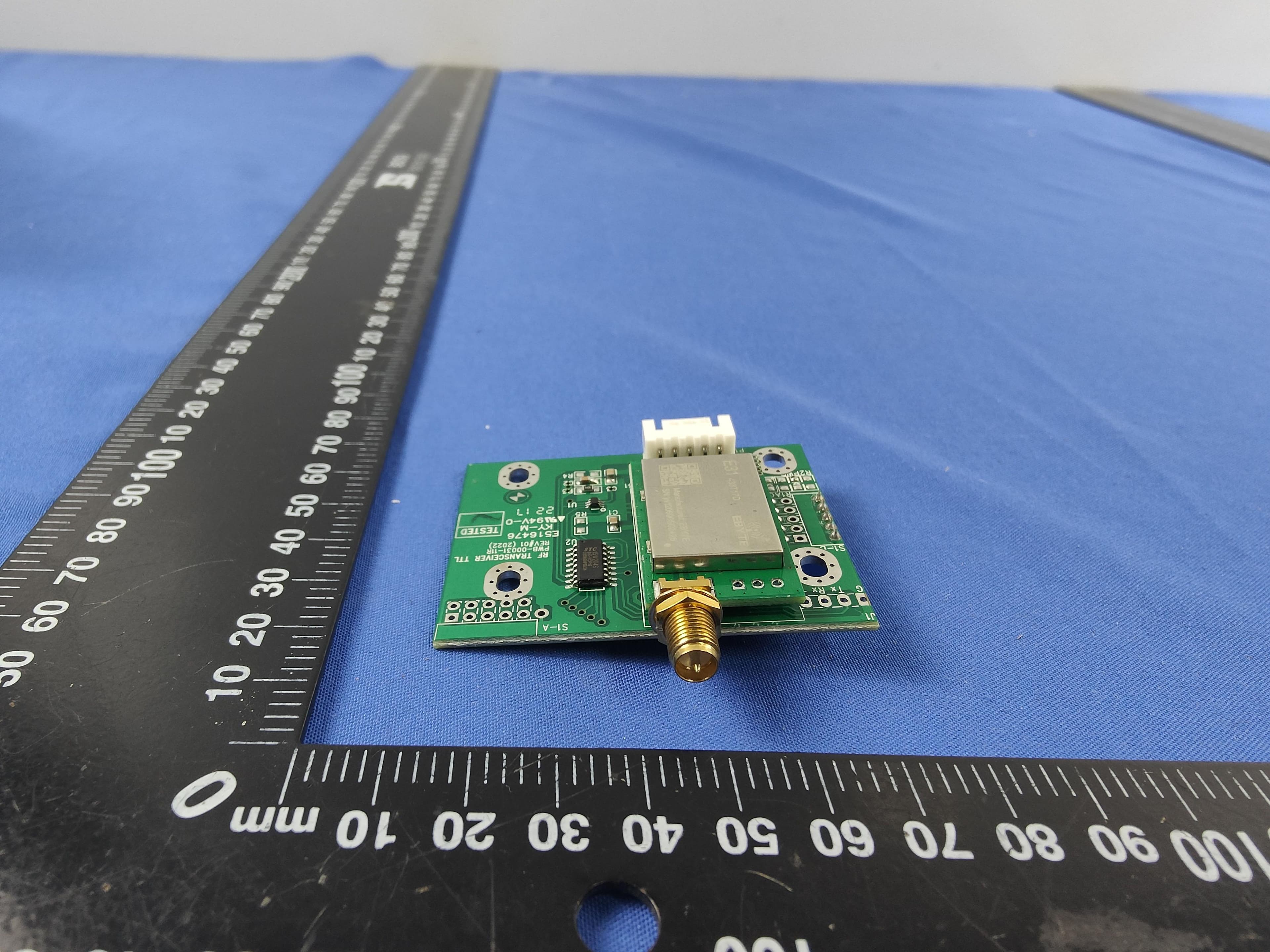
2AOW4-433UART
Aug 15, 2022433MHz Transceiver with UART interface
Equipment Class
DSC - Part 15 Security/Remote Control Transmitter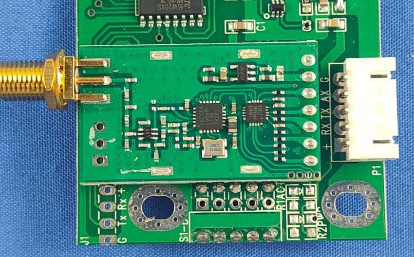
2AOW4-KTX900UART
Aug 14, 2022900MHz Transceiver with UART interface
Equipment Class
DXX - Part 15 Low Power Communication Device Transmitter