2AOW9-YW-017Wireless charging player
NET PROFIT GLOBAL COMPANY LIMITED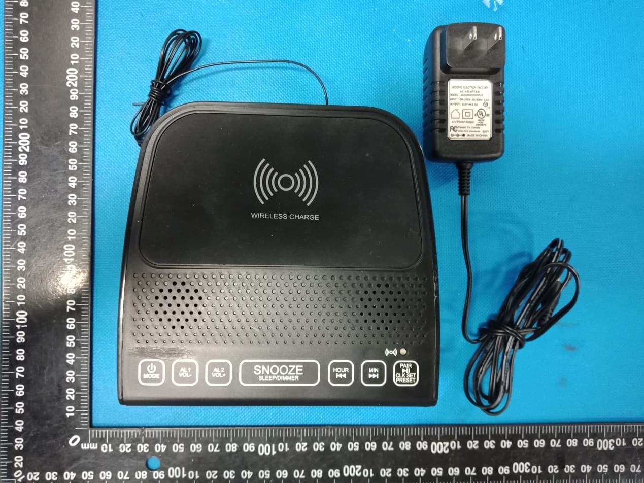
Click to zoom
Application Details
- Equipment Class
- DCD - Part 15 Low Power Transmitter Below 1705 kHz
- Date of Grant
- Jan 07, 2020
- Application Purpose
- Original Equipment
- Date of Application
- Jan 07, 2020
- Equipment Note
- Wireless charging player
- Frequency Range
- 0.12500000 - 0.12500000
- Country
- China
Documents & Files
Document Text
Text extracted from the exhibit documents filed with the FCC. Open a document above to read the original.
Users Manual
PLEASE READ BEFORE OPERATING THIS EQUIPMENT Instruction Manual WIRELESS PLAYER / FM RADIO / ALARM CLOCK & WIRELESS CHARGING Model: YW-017 CLK SET PRESET PAIR SNOOZE SLEEP/DIMMER AL1 VOL AL2 MODE ALOFF WIRELESS CHARGE MINHOUR FMRADIO FCC Warming FCC ID: 2AOW9-YW-017 Warning: Changes or modifications to this unit not expressly approved by the party responsible for compliance could void the user’s authority to operate the equipment. Note: This equipment has been tested and found to comply with the limits for a Class B digital device, pursuant to Part 15 of the FCC Rules. These limits are designed to provide reasonable protection against harmful interference in a residential installation. This equipment generates uses and can radiate radio frequency energy and, if not installed and used in accordance with the instructions, may cause harmful interference to radio communications. However, there is no guarantee that interference will not occur in a particular installation. If this equipment does cause harmful interference to radio or television reception, which can be determined by turning the equipment off and on, the user is encouraged to try to correct the interference by one or more of the following measures: ● Reorient or relocate the receiving antenna. ● Increase the separation between the equipment and receiver. ● Connect the equipment into an outlet on a circuit different from that to which the receiver is connected. ● Consult the dealer or an experienced radio/TV technician for help. This equipment complies with FCC radiation exposure limits set forth for an uncontrolled environment. This equipment should be installed and operated with minimum distance 20 cm between the radiator & your body. This device complies with Part 15 of the FCC Rules. Operation is subject to the following two conditions: (1) This device may not cause harmful interference, and (2) This device must accept any interference received, including interference that may cause undesired operation. 1 Main Location Controls 2 CLK SET PRESET PAIR SNOOZE SLEEP/DIMMER AL1 VOL AL2 MODE ALOFF WIRELESS CHARGE MINHOUR FMRADIO FRONTVIEW REARVIEW TOP VIEW 1 2 3 4 5 6 7 8 9 10 11 12 13 14 15 17 18 5V 1A 19 16 9V FOR CLOCKANDALARM BACKUPONLY IN THE BOTTOM Main Location Controls 3 1. WIRELESS CHARGING AREA 2. AL2 / VOL+ ( Alarm 2 set) Button 3. AL1 / VOL- ( Alarm 1 set) Button 4. POWER / MODE / AL OFF(Alarm Off) Button 5. SNOOZE / SLEEP / DIMMER Button 6. HOUR Button 7. MIN Button 8. WIRELESS CHARGING Indicator 9. PAIR / / CLK SET / PRESET(Radio) Button 10. SLEEP Indicator 11. PM (PM time) Indicator 12. LED DISPLAY 13. AL1 (Alarm 1 ) Indicator 14. AL2 (Alarm 2 ) Indicator 15. DC IN Jack 16. FM ANTENNA 17. AUX IN Input Port 18. USB CHARGING Port 19. BATTERY COMPARTMENT (For clock and alarm backup only) Setup Battery Operation Connect power adapter 1. Connect power adapter follow the figure. 2. After connection, the unit is in clock mode. NOTE: In any time, long press the POWER button to clock mode. Select sound source Press the MODE button repeatedly to select different sound source below: BT (Wireless) / RADIO (FM) / AUX In (Audio In / Line In) Using volume Press the VOL + or VOL - Buttons to increase or decrease the volume sound. 1. Remove the BATTERY door by carefully pushing batteries cover follow OPEN direction. The battery door can then be lifted away. 2. Following the polarity diagram as shown on the bottom cabinet insert 2 batteries and close the door. 3. Use only the size and type of batteries specified. For battery performance and longer operating time, we recommend the use of alkaline-type batteries. 4. Do not mix old and new batteries. 5. Do not mix alkaline, standard (carbon-zinc) or rechargeable (nickel-cadmium) batteries. 6. If the unit is not to be used for an extended period of time, remove the batteries. 7. Do not try to recharge batteries not intended to be recharged; they can overheat and rupture. 8. Do not dispose of batteries in fire, batteries may leak or explode. This unit operates on 2 X `AAA' size (UM-4) batteries (not included) for clock time / alarm setting backup only. NOTE: The Battery not support the unit main power. 4 CONNECTTODCINPUT JACKOF MAINUNIT AC ADAPTER PLUG THEADAPTER BODYTO AC OUTLET BATTER Y DOOR DC 1.5 V X 2 PCS UM-4 ( LR-03)OR“AAA”SIZE BOTTOM OF MAIN UNIT Automatic Scan radio station 1. Long press the POWER button to clock mode and press MODE button repeatedly to select RADIO mode. 2. When unit turn to radio mode, the display will show radio frequency. 3. Press and hold the PRESET button 5 seconds to scan through the frequency band and memory the station in preset. Scan radio station 1. In radio mode, press and hold the or SKIP buttons to search stations automatic forward and backward. 2. Press the or SKIP button to search stations manually forward and backward. NOTE: If FM reception is weak, fully extend the wire antenna and vary the position and location of the antenna until you find the strongest signal Using Radio Presets You can preset up to 20 FM stations for easy access as follows: 1. Long press the POWER button to clock mode and press MODE button repeatedly to select RADIO mode. 2. Tune the station you wish to preset. 3. Hold the PRESET button until “P01” appear and flash on the display. 4. Press the or SKIP button to select preset location and press the PRESET button once to confirm. 5. Repeat steps 2 through 4 to preset up to 20 stations. Recall preset station 1. Press the PRESET button once, the preset station show on display. 2. When preset station show, press the or SKIP button to search store preset which you wish to play. 1. Long press the POWER button to clock mode and press MODE button repeatedly to select AUX mode. 2. Plug the audio cable to AUX jack on the unit. 3. Plug the other end of audio cable to external device aux out / audio out / line out / phone out jack. 4. After turn on power of your external device, the external device will sound out from your unit speaker. Ra…
Text truncated - open the document above for the full version.
Cover Letter(s)
NET PROFIT GLOBAL COMPANY LIMITED Agent Authorization Company: NET PROFIT GLOBAL COMPANY LIMITED Address: RM 1421-22 14/F BLK A HI-TECH IND CTR, TSUEN WAN, N.T, HONG KONG, China Product Name: Wireless charging player Model Number(s): YW-017 Product Description: Wireless charging player We authorize MiCOM Labs Inc., 575 Boulder Court, Pleasanton, California 94566, USA, to act on our behalf on all matters concerning the certification of above named equipment. We declare that MiCOM Labs Inc. is allowed to forward all information related to the approval and certification of equipment to the regulatory agencies as required and to discuss any issues concerning the approval application. Any and all acts carried out by MiCOM Labs on our behalf shall have the same effect as acts of our own. Signature: Date: Jan. 06, 2020 Name: jiwen Yang Title: Manager Company: NET PROFIT GLOBAL COMPANY LIMITED
Cover Letter(s)
NET PROFIT GLOBAL COMPANY LIMITED Office of Engineering Technology Federal Communications Commission 7435 Oakland Mills Road Columbia, MD 21046 USA Date: Jan. 06, 2020 Subject; Request for Confidentiality FCC ID: 2AOW9-YW-017 To Whom It May Concern, Pursuant to the provisions of the Commission’s rules Title 47 Sections §0.457 and §0.459, we are requesting the Commission to withhold the following attachment(s) as confidential documents from public disclosure indefinitely. These documents contain detailed system and equipment descriptions and are considered as proprietary information in operation of the equipment. The public disclosure of these documents might be harmful to our company and would give competitors an unfair advantage in the market. Schematic Diagram Block Diagram Parts List Operational Description Tune-up Procedure It is our understanding that all measurement test reports, FCC ID label format and correspondence during the certification review process cannot be granted as confidential documents and this information will be available for public review once the grant of equipment authorization is issued. Sincerely, Signature: Name: jiwen Yang Title: Manager
External Photos
Annex A External Photos Report No.: HK1912233315‐1E/2E/3E Page 1 of 4 Report No.: HK1912233315‐1E/2E/3E Page 2 of 4 Report No.: HK1912233315‐1E/2E/3E Page 3 of 4 Report No.: HK1912233315‐1E/2E/3E Page 4 of 4
ID Label/Location Info
FCC ID LABEL: Ca. 2cm x 4cm Label Location FCC ID: 2AOW9-YW-017
Internal Photos
Annex B Internal Photo Report No.: HK1912233315‐1E/2E/3E Page 1 of 8 Report No.: HK1912233315‐1E/2E/3E Page 2 of 8 Report No.: HK1912233315‐1E/2E/3E Page 3 of 8 BT Antenna Report No.: HK1912233315‐1E/2E/3E Page 4 of 8 125 KHz Antenna Report No.: HK1912233315‐1E/2E/3E Page 5 of 8 Report No.: HK1912233315‐1E/2E/3E Page 6 of 8 Report No.: HK1912233315‐1E/2E/3E Page 7 of 8 Report No.: HK1912233315‐1E/2E/3E Page 8 of 8
Test Setup Photos
Test Model: YW-017 Radiated Emission Conducted Emission
Contact Information
Applicant
jiwen yang
Technical Contact
Test Firm
Shenzhen HUAK Testing Technology Co., Ltd.Jason Zhou
[email protected]+86-755-23029901
Technical Specifications
| # | Rule Parts | Frequency Range | Power Output |
|---|---|---|---|
| 1 | 15C | 0.125 MHz - 0.125 MHz | - |