2AOWY-0051Agricultural Transceiver
RealmFive, Inc.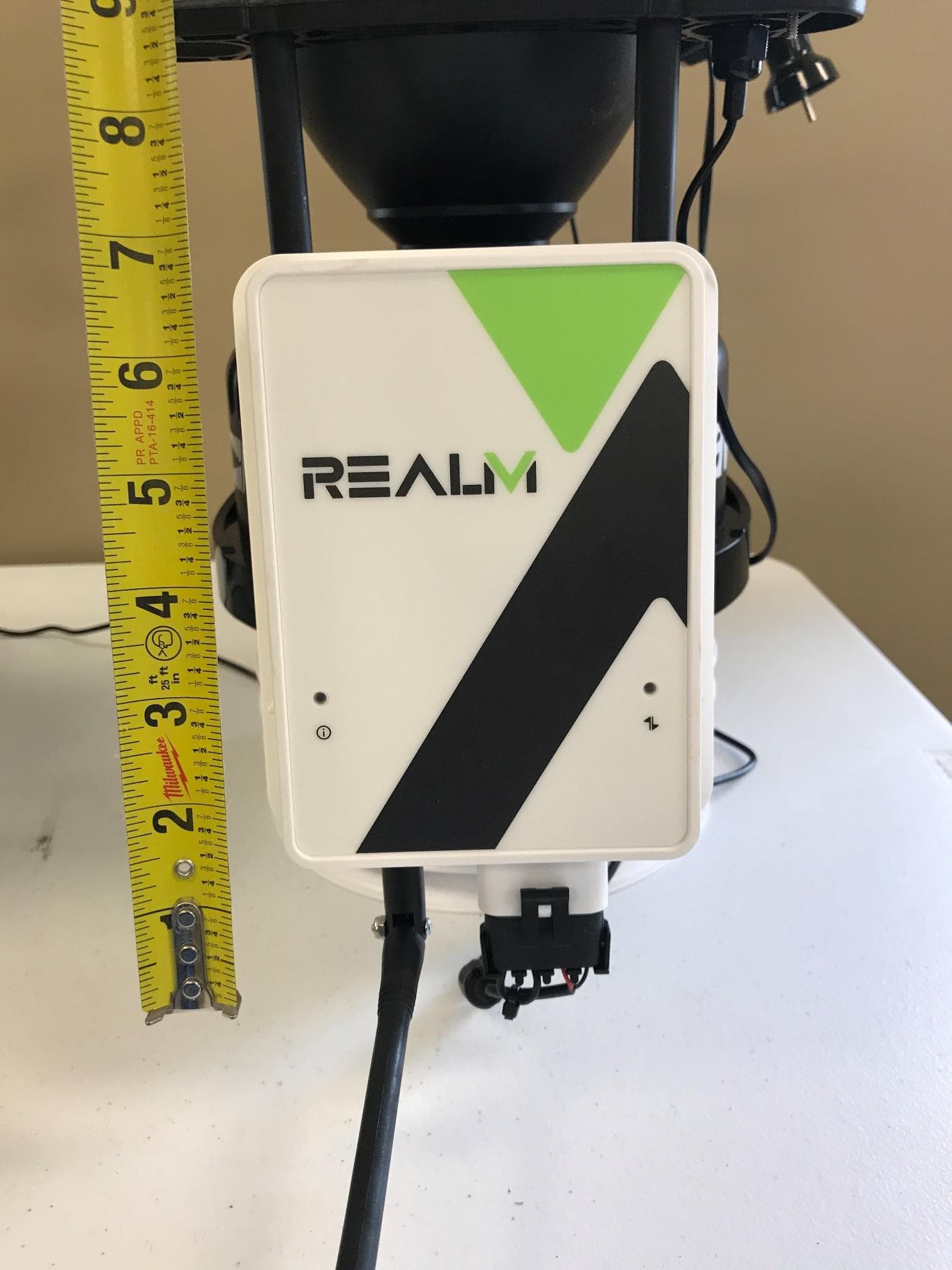
Click to zoom
Application Details
- Equipment Class
- DSS - Part 15 Spread Spectrum Transmitter
- Date of Grant
- Jul 06, 2023
- Application Purpose
- Original Equipment
- Date of Application
- Jul 06, 2023
- Equipment Note
- Agricultural Transceiver
- Frequency Range
- 902.30000000 - 914.90000000
- Company
- RealmFive, Inc.
- Country
- United States
Documents & Files
Document Text
Text extracted from the exhibit documents filed with the FCC. Open a document above to read the original.
Users Manual
USER’S MANUAL WeatherFront Phone: (844) 732-5624 Page 2 of 15 3300 Folkways Circle RealmFive.com Lincoln, NE 68504 Revision Sheet Release No. Date Revision Description Rev. A 07/16/2019 Release Phone: (844) 732-5624 Page 3 of 15 3300 Folkways Circle RealmFive.com Lincoln, NE 68504 Table of Contents 1 General .......................................................................................................................................... 4 1.1 System Overview .................................................................................................................. 4 1.2 Features ................................................................................................................................ 4 1.3 Acronyms and Abbreviations ............................................................................................... 5 1.4 Important FCC and IC Compliance Information ............................................................... 5 1.5 ESD Warning ........................................................................................................................ 5 1.6 Device Use Information ........................................................................................................ 5 1.6.1 Installation Packet Series ................................................................................................................. 5 1.6.2 User Input ....................................................................................................................................... 6 1.6.3 Indicator Description ....................................................................................................................... 6 1.6.4 Antenna Orientation......................................................................................................................... 7 1.6.5 Weather Station Power Connection .................................................................................................. 7 1.7 Cloud Data Services.............................................................................................................. 8 1.8 Points of Contact .................................................................................................................. 8 1.8.1 Installation User Interface ................................................................................................................ 8 1.8.2 Obtaining a Login ............................................................................................................................ 8 1.8.3 Obtaining Help ................................................................................................................................ 8 2 Installation ..................................................................................................................................... 9 Phone: (844) 732-5624 Page 4 of 15 3300 Folkways Circle RealmFive.com Lincoln, NE 68504 1 GENERAL 1.1 System Overview The WeatherFront monitors and reports temperature, humidity, barometric pressure, windspeed, wind direction, rainfall, and optionally, solar radiation, ultraviolet radiation, and leaf wetness. It is used in three different models: a Weather Station Gateway, a LoRa Weather Station, and a Cellular Weather Station. As a LoRa Weather Station it reports weather data through a Data Gateway via LoRa radio. As Weather Station Gateway or Cellular Weather Station it reports weather data via cellular modem. As a Weather Station Gateway, it is also capable of serving as the link between end devices and the cloud data server in the Internet of Things (IoT) for agriculture. As a gateway it listens for LoRa data packets from end devices and periodically makes a cellular data connection to forward the accumulated end device packets to a server along with its own data packets. It also acknowledges packets from end devices. And it holds downlink packets from the server for end devices and sends them to the device after the next uplink packet from that device in lieu of an acknowledge. 1.2 Features The WeatherFront includes the following features: • Six RJ11 connectors for external sensors • A barometric pressure sensor • Low power microcontroller • Low power, long range radio for communication with end devices or a Data Gateway • Cellular data modem (optional) • GPS receiver for device location • Non-volatile memory for configurable settings • Non-volatile memory for uplink and downlink packet queues • Red-green-blue LED status and cellular RSSI indicators • Accelerometer for user input • Solar charged LiFePO4 41 W-Hr battery pack • Powered by a 10 W Solar Panel Phone: (844) 732-5624 Page 5 of 15 3300 Folkways Circle RealmFive.com Lincoln, NE 68504 1.3 Acronyms and Abbreviations Term Description API Application Interface FCC Federal Communications Commission GPS Global Positioning System Hr Hour ID Unique Identification Number IoT Internet of Things LED Light Emitting Diode LiFePO4 Lithium Iron Phosphate QR Quick Response RSSI Received Signal Strength Indication s Seconds URL Universal Resource Locator UTC Universal Time Coordinated V Volts W Watt 1.4 Important FCC and IC Compliance Information Changes or modifications not expressly approved by the manufacturer could void the user’s authority to operate this equipment. This product meets the applicable FCC Part 15 rules. Operation is subject to the following two conditions: (1) this device may not cause interference, and (2) this device must accept any interference, including interference that may cause undesired operation of the device. To limit RF exposure, please ensure 8 inches (20 cm) of separation from the transmitter antennas at all times. 1.5 ESD Warning The WeatherFront half of the enclosure must be unlatched from the back half of the enclosure to connect the various sensors. Care should be taken not to touch the circuit board inside the WeatherFront as the circuit is susceptible to damage from ESD. 1.6 Device Use Inf…
Text truncated - open the document above for the full version.
Attestation Statements
R=Al-l t Certification Application Attestation Statements Date: April 12,2023 American Certification Body, Inc. 313 Park Avenue Suite 300 Falls Church, VA 22046 To Whom It May Concern: Statement for 47 CFR section 2.911(dXSXi) RealmFive. Inc. certifies that as of the date of the application the equipment for which authorization is sought is not "covered" equipmentl prohibited from receiving an equipment authorization pursuant to section 2.903 of the FCC rules. If the equipment for which the applicant seeks authorization is produced by any of the entities identified on the current Covered List, including affiliates or subsidiaries of the named companies, the applicant must include an explanation on why the equipmeht is not "covered" equipment. Additional Explanation: <N/A> Statement for 47 CFR section 2.911(dX5Xii) RealmFive. Inc. ("the applicant") certifies that, as of the date of the filing of this application, the equipment is not identified on the Covered List as an entity producing "covered" equipment. Thank you, By: Title: Company: Timothy Adkins (Print name) Embedded Systems Engineer RealmFive, Inc Telephone: (844)732-s624 r-'IheCornrnission'sCorcrcdl.istispublishedbythePublicSaferyandllornelandSecurityBureauandpostedontheCotnmission's website. Thrs Covered List, which is periodically updated, identihes particular equiprnent, produced by particular entities, that constitutes "covered" equiptnent. https://www.fcc,gov/supplvchain/coveredlist . 3300 Folkways Cr. Lincoln, NE 68504 (844)REALM-AC ,de*
Attestation Statements
R=Al-l t U.S. Agent Designation for Service of Process TO: American Certification Body, lnc. 313 ParkAvenue Suite 300 Falls Church,VA 22046 ATTENTION: FCC Certification - Section 2.911(dX7) Information This letter is to confirm that the Applicant will also serve as the U.S. Agent for Service of Process as required by 47 CFR 2.911(d)(7). The Applicant acknowledges that they must maintain an agent for no less than one year after terminating all marketing and impoftation OR the conclusion of any Commission-related proceeding involving the equipment. The Applicant further acknowledges their responsibility to inform the FCC whenever the Designated U.S. Agent information changes. Applicant Company name: RealmFive, lnc. FRN:0027176841 Grantee Code: 2AOWY Contact Name: Timothy Adkins Street Address: 3300 Folkways Circle City/Province/Zip: Lincoln, NE 68504 Telephone No: (844)732-5624 Email : [email protected] Applicant Signature: Date: O+-l2- 7o2\ Y,*ar-, ).tu r Signed by (Printed Name/Title): Timothy Adkins 3300 Folkways Cr. Lincoln, NE 68504 (844)REALM AC
Cover Letter(s)
` 042622-16 Authority to Act as Agent Date: 5 May 2023 American Certification Body, Inc. 313 Park Avenue Suite 300 Falls Church, VA 22046 To Whom It May Concern: Nic Johnson of the Nebraska Center for Excellence in Electronics is authorized to act on our behalf, until otherwise notified, for applications to American Certification Body, Inc. (ACB). We certify that we are not subject to denial of federal benefits, that includes FCC benefits, pursuant to Section 5301 of the Anti-Drug Abuse Act of 1988, 21 U.S.C. 862. Further, no party, as defined in 47 CFR 1.2002 (b), to the application is subject to denial of federal benefits, that includes FCC benefits. We also declare that the information provided to the FCC is true and correct to the best of our knowledge (47 CFR 2.911(d)) and we have been informed of the grantee responsibilities (47 CFR 2.909) with regard to certified equipment. Thank you, Agency Agreement Expiration Date: 12 months By: ____ ______________________ Timothy Adkins________________ (Signature 1 ) (Print name) Title: Embedded Systems Engineer___ On behalf of: RealmFive Inc.______________ (Company Name) Telephone: (402) 301-9618_______________ 1 - Must be signed by applicant contact given for applicant on the FCC site, or by the authorized agent if an appropriate authorized agent letter has been provided. Letters should be placed on appropriate letterhead.
Cover Letter(s)
022818 – 11 Request for Confidentiality Date: Subject: Confidentiality Request for: Pursuant to FCC 47 CFR 0.457(d) and 0.459 and IC RSP-100, Section 9.4, the applicant requests that a part of the subject FCC application be held confidential. Type of Confidentiality Requested Exhibit ☐ Short Term ☒ Permanent Block Diagrams ☐ Short Term External Photos ☐ Short Term ☐ Permanent * 3 Internal Photos ☐ Short Term ☒ Permanent Operation Description/Theory of Operation ☐ Short Term ☒ Permanent Schematics ☐ Short Term Test Setup Photos ☐ Short Term ☐ Permanent * 3 User’s Manual RealmFive has spent substantial effort in developing this product and it is one of the first of its kind in industry. Having the subject information easily available to "competition" would negate the advantage they have achieved by developing this product. Not protecting the details of the design will result in financial hardship. Permanent Confidentiality: The applicant requests the exhibits listed above as permanently confidential be permanently withheld from public review due to materials that contain trade secrets and proprietary information not customarily released to the public. Short-Term Confidentiality: The applicant requests the exhibits selected above as short term confidential be withheld from public view for a period of ___(specify number of days not to exceed 180) 4 ___ days from the date of the Grant of Equipment Authorization and prior to marketing. This is to avoid premature release of sensitive information prior to marketing or release of the product to the public. Applicant is also aware that they are responsible to notify ACB in the event information regarding the product or the product is made available to the public before the requested period has expired. ACB will then release the documents listed above for public disclosure pursuant to FCC Public Notice DA 04-1705. Sincerely, By: __________________________ Nic Johnson, NCEE Labs (Signature/Title 5 ) (Print name) 3 - The asterisked items (*) require further information to be provided to ACB before permanent confidentiality will be extended to these exhibits. Please refer to FCC KDB 726920 and the specific Document link for D01 found at: https://apps.fcc.gov/oetcf/kdb/forms/FTSSearchResultPage.cfm?switch=P&id=41731 and review section II, 3) regarding specific information that must accompany these requests. 4 - Please refer to http://acbcert.com/documents/misc-docs/Memo-Short-Term-Vs-Standard-Confidentiality.pdf for complete details. 5 - Must be signed by applicant contact given for applicant on the FCC site, or by the authorized agent if an appropriate authorized agent letter has been provided. Letters should be placed on appropriate letterhead.
External Photos
EXTERNAL PHOTOS EXTERNAL PHOTOS EXTERNAL PHOTOS EXTERNAL PHOTOS
ID Label/Location Info
Label Note: upper label will be different based on which certified cellular module option is used. See following pages for labels for each. Label Label Label
Internal Photos
INTERNAL PHOTOS Page 1 of 6 INTERNAL PHOTOS Page 2 of 6 INTERNAL PHOTOS Page 3 of 6 INTERNAL PHOTOS Page 4 of 6 INTERNAL PHOTOS Page 5 of 6 Cellular antennas INTERNAL PHOTOS Page 6 of 6
RF Exposure Info
RF Exposure Evaluation Page 1 of 3 Reference: CFR 47 FCC Part 1.1310 Description: Both transmitters in the device have the possibility of transmitting simultaneously. The worst-case exposure for each transmitter was used to calculate the percentage of the allowable limit that each transmitter contributed. All of the percentages were then added together to verify that at the specified operating distance, they were below the allowable limit. All measurements were peak or RMS power readings taken from test reports from accredited test labs. Antenna gains were taken from the manufacturer’s specifications. Limits: Maximum exposure limits from CFR 47, FCC Part 1.1310: Table 1 - Limits for Maximum Permissible Exposure (MPE) Frequency range (MHz) Electric field strength (V/m) Magnetic field strength (A/m) Power density (mW/cm 2 ) Averaging time (minutes) (A) Limits for Occupational/Controlled Exposure 0.3-3.0 614 1.63 *100 6 3.0-30 1842/f 4.89/f *900/f 2 6 30-300 61.4 0.163 1.0 6 300-1,500 f/300 6 1,500-100,000 5 6 (B) Limits for General Population/Uncontrolled Exposure 0.3-1.34 614 1.63 *100 30 1.34-30 824/f 2.19/f *180/f 2 30 30-300 27.5 0.073 0.2 30 300-1,500 f/1500 30 1,500-100,000 1.0 30 RF Exposure Evaluation Page 2 of 3 FCC RFx Calculations: Transmitter Frequency Antenna Gain Power Power +10% for tolerance Power Density Limit at specified distance % of limit Highest Total FCC ID MHz numerical mW mW mW/cm^2 mW/cm^2 1 902.3 0.91 47.34 52.07 0.0094 0.6015 1.57% 1 1.57% 2A0WY-004B 2A 779 1.54 230.00 253.00 0.078 0.5193 14.93% RI7LE866SV1 2A 1710 2.09 181.55 199.705 0.0830 1.0000 8.30% RI7LE866SV1 2B 1720 2.09 238.8 262.68 0.1092 1.0000 10.92% RI7XE866A1NA 2B 704 1.54 212.3 233.53 0.0715 0.4693 15.24% RI7XE866A1NA 2C 1850 2.09 302.00 332.2 0.1382 1.0000 13.82% XPY2AGQN4NNN 2C 824 1.54 316.0 347.6 0.1065 0.5493 19.39% 1 19.39% XPY2AGQN4NNN TOTAL 20.96% Table 2 - Calculations according to CFR 47, Part 1.1310, Table 1(B) Specified distance = 20 cm For each radio, the frequency with the lowest limit was used and the highest power of all frequency bands to calculate the worse-case RF exposure. When measurements were performed as EIRP, the antenna gain is listed as 1. In cases where the antenna gain is not listed as 1, the power measurement was performed as conducted and the antenna gain from the manufacturer’s datasheet was used. Transmitter 1 peak antenna gain = -0.4 dBi = 0.91 numeric gain RF Exposure Evaluation Page 3 of 3 Transmitter 1: FCC ID: 2A0WY-0048 Transmitter 2: Is only one of the following: Transmitter Description Part Number FCC ID 2A Digi XBee Cellular LTE CAT 1 XBC-V1-UT-001 RI7LE866SV1 2B Digi XBee3 Cellular LTE CAT 1 XB3-C-A1-UT-001 RI7XE866A1NA* 2C Digi XBee3 Cellular LTE-M XB3-C-A2-UT-001 XPY2AGQN4NNN* Module 2A through 2c antenna gain = 1.9 dBi = 1.54 numeric in 698 – 960 MHz band. = 3.2 dBi = 2.09 numeric in the 1710 – 2690 band. See datasheet for details The power density is calculated as shown below: S = (P x G)/(4 x π x d^2) d = 20 cm - used to calculate exposure at 20 cm 1 mW/cm^2 = 10 W/m^2 *Note: This device also includes Bluetooth functionality, but is not used. It is blocked in the firmware and the user has no way of accessing it. The module will also show FCC ID: MCQ-XB3M1. FCC ID: MCQ-XB3C1, but no functionality contained under this certification is used or available to the user.
Test Report
The Nebraska Center for Excellence in Electronics (NCEE) authorizes the above named company to reproduce this report provided it is reproduced in its entirety for use by the company’s employees only. Any use that a third party makes of this report, or any reliance on or decisions made based on it, are the responsibility of such third parties. NCEE accepts no responsibility for damages, if any, suffered by any third party as a result of decisions made or actions based on this report. This report applies only to the items tested. Amended FCC/ISED Test Report Prepared for: RealmFive, Inc. Address: 3300 Folkways Cir. Lincoln, NE 68504 Product: WeatherFront Test Report No: R20190618-20C Approved By: __________________ Nic S. Johnson, NCE Technical Manager iNARTE Certified EMC Engineer #EMC-003337-NE DATE: 22 June 2023 Total Pages: 52 Report Number: R20190618-20 Rev C Prepared for: Realm Five, Inc. The Nebraska Center for Excellence in Electronics 4740 Discovery Drive Lincoln, NE 68521 Page 2 of 52 REVI S I ON PAGE Rev. No. Date Description 0 23 July 2019 Original – NJohnson Prepared by KVepuri A 16 September 2019 Modified Section 2.2 Includes NCEE Labs report R20190618-20 and its amendment in full. -NJ B 21 June 2023 Added note on pg 47 and corrected duty cycle on pg 48 C 30 June 2023 Corrected typo on pg 48 Report Number: R20190618-20 Rev C Prepared for: REALM Agriculture The Nebraska Center for Excellence in Electronics 4740 Discovery Drive Lincoln, NE 68521 Page 3 of 52 C ON T EN TS Revision PAge ................................................................................................................................................ 2 1.0 Summary of test results ........................................................................................................................... 4 2.0 EUT Description ........................................................................................................................................ 5 2.1 Equipment under test ............................................................................................................................ 5 2.2 Description of test modes .................................................................................................................... 6 2.3 Description of support units ............................................................................................................... 6 3.0 Laboratory description ............................................................................................................................ 7 3.1 Laboratory description ......................................................................................................................... 7 3.2 Test Personnel ........................................................................................................................................ 7 3.3 Test equipment ....................................................................................................................................... 8 4.0 Detailed results ......................................................................................................................................... 9 4.1 Duty Cycle ................................................................................................................................................ 9 4.2 Radiated emissions ............................................................................................................................. 10 4.3 Peak Output Power .............................................................................................................................. 19 4.4 Bandwidth .............................................................................................................................................. 23 4.5 Bandedges ............................................................................................................................................. 31 4.6 Power Spectral Density ...................................................................................................................... 41 4.7 Carrier frequency seperation, number of hopping channels, time of occupancy............... 45 Appendix A: Sample Calculation ....................................................................................................................... 49 Appendix B – Measurement Uncertainty .......................................................................................................... 51 REPORT END......................................................................................................................................................... 52 Report Number: R20190618-20 Rev C Prepared for: REALM Agriculture The Nebraska Center for Excellence in Electronics 4740 Discovery Drive Lincoln, NE 68521 Page 4 of 52 1.0 SUMMARY OF TEST RESULTS The EUT has been tested according to the following specifications: APPLIED STANDARDS AND REGULATIONS Standard Section Test Type Result FCC Part 15.35 RSS Gen, Issue 4, Section 6.10 Duty Cycle Pass FCC Part 15.247(a)(1) RSS-247 Issue 2 Section 5.2 Peak output power Pass FCC Part 15.247(a)(1) RSS-247 Issue 2 Section 5.2 Bandwidth Pass FCC Part 15.209 RSS-Gen Issue 4, Section 7.1 Receiver Radiated Emissions Pass FCC Part 15.209 (restricted bands), 15.247 (unrestricted) RSS-247 Issue 2 Section 5.5, RSS-Gen Issue 4, Section 8.9 Transmitter Radiated Emissions Pass FCC Part 15.247(a)(1) RSS-247 Issue 2 Section 5.2 Power Spectral Density Pass FCC 15.247(a) (1) (i) RSS-247, 5.1(c) Frequency Hopping System Pass FCC Part 15.209, 15.247(d) RSS-247 Issue 2 Section 11.13 Band Edge Measurement Pass FCC Part 15.207 RSS-Gen Issue 4, Section 7.1 Conducted Emissions Not applicable. Battery power only, no charger. FCC 15.203 Unique Antenna Requirement Pass See Section 4 for details on the test methods used for each test. Report Number: R20190618-20 Rev C Prepared for: REALM Agriculture The Nebraska…
Text truncated - open the document above for the full version.
Test Report
– 1 – Revised 5/1/15 Product Description Designed for permanent attachment, the PML ½-wave whip tilts 180 degrees and delivers outstanding performance in a cost-effective package. An internal counterpoise eliminates external ground plane dependence and maximizes performance. The antenna is attached by placing its base through a ¼" (6.35 mm) hole in the product and securing it with a nut or by threading it into a PEM-style insert. This method of attachment is highly secure and saves the cost of an antenna connector. The PML attaches to a PCB or connector via 12" (30.48 cm) of RG-178 coax cable. It is also available with 1.32 mm coax cable terminated with a U.FL/MHF compatible connector. This saves the labor of adding a connector while using one that is small enough to fit through the antenna’s mounting hole. Custom lengths and terminations are available by special order. Features • Cost-effective • Internal counterpoise • Tilts 180 degrees • Outstanding performance • Omni-directional pattern • Low VSWR • Integral 12" (30.48 cm) RG-178 coax cable or 1.32 mm coax (U.FL) Electrical Specifications Center Frequency: 916MHz Recom. Freq. Range: 881-951MHz Wavelength: ½-wave VSWR: ≤1.9 typical at center Peak Gain: –0.4dBi Impedance: 50-ohms Connection: Straight-cut or U.FL/MHF Cable: 12" (30.48 cm) RG-178 coax or 1.32 mm coax (U.FL) Oper. Temp. Range: –40°C to +90°C Electrical specifications and plots measured on 10.16 cm x 10.16 cm (4.00" x 4.00") reference ground plane ANT-916-PML-xxx Data Sheet by Ordering Information ANT-916-PML (with straight cut RG-178 coax) ANT-916-PML-UFL (with U.FL/MHF compatible connector and 1.32mm coax) 12.1 mm (0.48") 35.2 mm (1.39") 8.2 mm (0.32") 123.0 mm (4.84") 7.9 mm (0.31") 150.3 mm (5.92") 6.0 mm (0.24") Available with Straight Cut Cable or U.FL Connector I-PEX silhouette shown in shadow – 2 – by Data Sheet ANT-916-PML-xxx VSWR Graph What is VSWR? The Voltage Standing Wave Ratio (VSWR) is a measurement of how well an antenna is matched to a source impedance, typically 50-ohms. It is calculated by measuring the voltage wave that is headed toward the load versus the voltage wave that is reflected back from the load. A perfect match will have a VSWR of 1:1. The higher the first number, the worse the match, and the more inefficient the system. Since a perfect match cannot ever be obtained, some benchmark for performance needs to be set. In the case of antenna VSWR, this is usually 2:1. At this point, 88.9% of the energy sent to the antenna by the transmitter is radiated into free space and 11.1% is either reflected back into the source or lost as heat on the structure of the antenna. In the other direction, 88.9% of the energy recovered by the antenna is transferred into the receiver. As a side note, since the “:1” is always implied, many data sheets will remove it and just display the first number. How to Read a VSWR Graph VSWR is usually displayed graphically versus frequency. The lowest point on the graph is the antenna’s operational center frequency. In most cases, this will be different than the designed center frequency due to fabrication tolerances. The VSWR at that point denotes how close to 50-ohms the antenna gets. Linx specifies the recommended bandwidth as the range where the typical antenna VSWR is less than 2:1. VSWRReflected Power 3:1 2:1 1:1 25% 11% 0% 916MHz1016MHz816MHz 1.131
Test Report
W3554.A (06/20) 1 Internal 5G/4G PCB Antenna with Cable Assembly W3554xxxxx - 698 to 6000 MHz PulseLarsenAntennas.com Applications: Coaxial cable feed Multiple cable lengths and connector options (U-FL, SMA, MMCx and custom) 2G/3G/4G/5G GNSS WiFi, Bluetooth, BLE, Zigbee ISM 868, 915, 2400, 5000MHz Electrical Specifications @ 25°C - Operating Temperature -40°C to +85°C 1 Frequency Bands: 698-960/1400-1600/1710-2690/3300-3800/4900-6000 MHz Antenna Type Nominal Impedance Return Loss Radiation Pattern PolarizationPower Withstanding Monopole50Ωper belowOmniLinear5W Frequency698-960 MHz1400-1600 MHz1710-2690 MHz3300-3800 MHz4900 - 6000 MHz Return Loss-4 dB-3 dB-6 dB-5 dB-4 dB Peak Gain1.9 dBi2.5 dBi3.2 dBi3.3 dBi3.5 dBi Average Efficiency45%53%66%57%37% Part NumberCable Length (mm)Cable OD (mm)Connector Type W3554B01401431 .13U.FL Compatible W3554B0140T1431 .13U.FL Compatible with ADH W3554B01701701 .13U.FL Compatible W3554B02932931 .13U.FL Compatible W3554E01931931 .13Right angle MMCX male W3554G01001001 .13SMA male W3554G02542541 .13SMA male W3554G03843841.37SMA male W3554G04574571 .13SMA male W3554K01531531.37Right angle SMA male Notes: 1. Storage Temperature: -40°C to 85°C 2. Other connector types and custom cable lengths are available upon request Mechanical Specifications Orderable PN: W3554xxxx (per below cable and connector options) Size (L x W x H) ColorWeight 30 x 120 x 0.2 mmGreen PCB1.5 grms W3554.A (06/20) 2 Internal 5G/4G PCB Antenna with Cable Assembly W3554xxxxx - 698 to 6000 MHz PulseLarsenAntennas.com Mechanical W3554xxxxx Packaging Info: 5PCS/PE bag 20PCS PE bag/Foam bag 10PCS foam bag/Carton box Total: 1000PCS/Carton box W3554.A (06/20) 3 Internal 5G/4G PCB Antenna with Cable Assembly W3554xxxxx - 698 to 6000 MHz PulseLarsenAntennas.com Charts W3554xxxxx -25.0 -20.0 -15.0 -10.0 -5.0 0.0 Frequency(MHz) 610727844961 10781194131114281545166217791896201321292246236324802597271428312948306431813298 3415 35323649 3766 388339994116423343504467 45844701 4818 4934505151685285540255195636575358695986 Return LossSpec Return Loss 0 10 20 30 40 50 60 70 80 90 Frequency (MHz ) 738 798858918960 177018601950 2040 21302200229023802470256026502740 28302920300031503300345036003750 3900405042004350450046504800 49505100525054005550570058506000 Efficiency (%) Peak Gain (dBi) -4 -3 -2 -1 0 1 2 3 4 5 Freque ncy (M Hz ) 738798858918960 17701860195020402130220022902380247025602650274028302920300031503300345036003750390040504200435045004650480049505100525054005550570058506000 W3554.A (06/20) 4 Internal 5G/4G PCB Antenna with Cable Assembly W3554xxxxx - 698 to 6000 MHz PulseLarsenAntennas.com Charts 698MHz - 960MHz 1400MHz - 1600MHz Free Space Radiation Pattern Free Space Radiation Pattern Horizontal PlaneElevation Plane Horizontal PlaneElevation Plane W3554.A (06/20) 5 Internal 5G/4G PCB Antenna with Cable Assembly W3554xxxxx - 698 to 6000 MHz PulseLarsenAntennas.com Charts 1710MHz - 2690MHz 3300MHz - 3800MHz Free Space Radiation Pattern Free Space Radiation Pattern Horizontal PlaneElevation Plane Horizontal PlaneElevation Plane 6 PulseLarsenAntennas.com W3554.A (06/20) Internal 5G/4G PCB Antenna with Cable Assembly W3554xxxxx - 698 to 6000 MHz For More Information: Americas - [email protected] | Europe - [email protected] | Asia - [email protected] | Questions? +1-800-ANTENNA Performance warranty of products offered on this data sheet is limited to the parameters specified. Data is subject to change without notice. Other brand and product names mentioned herein may be trademarks or registered trademarks of their respective owners. © Copyright, 2020. Pulse Electronics, Inc. All rights reserved. Charts 4900MHz - 6000MHz Free Space Radiation Pattern Horizontal PlaneElevation Plane Mouser Electronics Authorized Distributor Click to View Pricing, Inventory, Delivery & Lifecycle Information: Pulse: W3554G0384 W3554B0293 W3554E0193 W3554G0100 W3554G0457 W3554K0153 W3435B0100 W3554B0170 W3554G0254
Test Setup Photos
TEST SETUP PHOTOS TEST SETUP PHOTOS
Contact Information
Applicant
Timothy A Adkins
Technical Contact
RealmFive, Inc.Timothy Adkins
[email protected]4023019618
3300 Folkways Circle · Lincoln · United States
Non-Technical Contact
RealmFive, Inc.Timothy Adkins
[email protected]4023019618
Test Firm
Nebraska Center for Excellence in ElectronicsKarthik Vepuri
Technical Specifications
| # | Rule Parts | Frequency Range | Power Output |
|---|---|---|---|
| 1 | 15C | 902.3 MHz - 914.9 MHz | 47.00 mW |
Other Applications from RealmFive, Inc.
2AOWY-004A
May 16, 2023Remote Sensor
Equipment Class
DSS - Part 15 Spread Spectrum Transmitter
2AOWY-004B
Jun 27, 2021Data Gateway
Equipment Class
DSS - Part 15 Spread Spectrum Transmitter