2AOYX-NOYP3Arsenal 2 Pro
North of You, LLC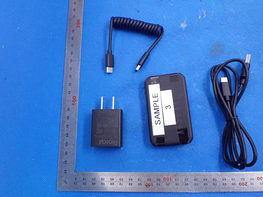
Click to zoom
Application Details
- Equipment Class
- NII - Unlicensed National Information Infrastructure TX
- Date of Grant
- May 30, 2021
- Application Purpose
- Original Equipment
- Date of Application
- May 30, 2021
- Equipment Note
- Arsenal 2 Pro
- Frequency Range
- 5745.00000000 - 5825.00000000
- Company
- North of You, LLC
- Country
- United States
Documents & Files
Document Text
Text extracted from the exhibit documents filed with the FCC. Open a document above to read the original.
Users Manual
Arsenal 2 Pro User’s Manual Rev 0.3 Arsenal 2 Pro User’s Manual North of You, LLC 90 West Madison Ave Suite E-237 Belgrade, MT 59714 Phone: 1-877-727-7362 Arsenal 2 Pro User’s Manual Rev 0.3 Table of Contents Document Overview4 Document Revision History4 Arsenal 2 Pro Overview4 Arsenal 2 Pro Specifications4 Input Power4 Operating Environment4 What’s included with Arsenal 2 Pro?5 Arsenal 2 Pro5 Coiled USB Cable5 Charger and Charger Cable5 Phone App6 Quick Tour of Arsenal 2 Pro7 Power Button7 Status Indicators7 Charger Connector8 Camera Connector8 Hot Shoe Slide8 Quick Tour of App9 Smart Mode9 Manual Mode10 Timelapse11 Settings12 Setup Instructions13 Instructions13 Charging Instructions15 To charge:15 Important Handling Information16 USB Ports and Button16 Arsenal 2 Pro Temperature16 Storage16 Cleaning17 Disposal17 Safety Warnings18 North of You, LLC 2 Arsenal 2 Pro User’s Manual Rev 0.3 Troubleshooting Tips19 Contacting Support19 Regulatory Information Model - Robert20 Regulatory Screen in the Arsenal 2 App20 RF Transmitter21 Maximum RF Transmitter Power21 SAR21 FCC22 IC22 Europe23 Australia23 North of You, LLC 3 Arsenal 2 Pro User’s Manual Rev 0.3 1. Document Overview This document contains the specifications and features of Arsenal 2 Pro - The Intelligent Camera Assistant. It also contains setup and maintenance instructions. 2. Document Revision History DateRevisionRevision Changes 2021/02/090.1Initial creation of the document. 2021/04/070.2Updated Regulatory Screenshot from App. 2021/05/070.3Updated Regulatory information. 3. Arsenal 2 Pro Overview Arsenal 2 Pro is an intelligent camera assistant. It connects to a DSLR or mirrorless camera over USB and allows for remote control of the camera from a smartphone via WIFI. Arsenal 2 Pro provides tools to assist in photo stacking, timelapses, and producing long exposures. Lastly, it uses machine learning to suggest settings to the user based on the current subject being photographed and data from the camera and onboard sensors. 4. Arsenal 2 Pro Specifications a. Input Power Charger Input PowerRating AC Power100-240VAC 50/60Hz Max 0.3A Arsenal 2 Pro Input PowerRating USB Charger Connection5VDC 1.0A b. Operating Environment FactorMetricUS Temperature0°C to 35°C32°F to 95°C Humidity10% to 90%10% to 90% North of You, LLC 4 Arsenal 2 Pro User’s Manual Rev 0.3 North of You, LLC 5 Arsenal 2 Pro User’s Manual Rev 0.3 5. What’s included with Arsenal 2 Pro? a. Arsenal 2 Pro b. Coiled USB Cable c. Charger and Charger Cable i.Note: Not included in non-US models. North of You, LLC 6 Arsenal 2 Pro User’s Manual Rev 0.3 d. Phone App i.Downloaded from the Google Play Store or Apple App Store. North of You, LLC 7 Arsenal 2 Pro User’s Manual Rev 0.3 6. Quick Tour of Arsenal 2 Pro a. Power Button i.Button to power On and power Off Arsenal 2 Pro. ii.If Arsenal 2 Pro is Off, a single momentary short press will power On Arsenal 2 Pro. The power indicator will illuminate and the LED Bar will display an animation after Arsenal 2 Pro has booted. iii.If Arsenal 2 Pro is On, a single momentary short press will power Off Arsenal 2 Pro. The LED Bar on Arsenal 2 Pro will display a short animation before powering off. b. Status Indicators Power Indicator Off Arsenal 2 Pro Powered Off OnArsenal 2 Pro Powered On Charging Indicator Off Arsenal 2 Pro not charging OnArsenal 2 Pro charging BlinkingCharger Halted North of You, LLC 8 Arsenal 2 Pro User’s Manual Rev 0.3 c. Charger Connector i.Used to charge Arsenal 2 Pro with the provided Charger and Charger Cable. d. Camera Connector i.Used to connect Arsenal 2 Pro to the Camera with the Coiled USB Cable. e. Hot Shoe Slide i.Used to secure Arsenal 2 Pro to the Hot Shoe on a DSLR or mirrorless camera. North of You, LLC 9 Arsenal 2 Pro User’s Manual Rev 0.3 7. Quick Tour of App a. Smart Mode North of You, LLC 10 Arsenal 2 Pro User’s Manual Rev 0.3 b. Manual Mode North of You, LLC 11 Arsenal 2 Pro User’s Manual Rev 0.3 c. Timelapse North of You, LLC 12 Arsenal 2 Pro User’s Manual Rev 0.3 d. Settings North of You, LLC 13 Arsenal 2 Pro User’s Manual Rev 0.3 8. Setup Instructions a. Instructions i.Slide the Arsenal 2 Pro into the Hot Shoe of the Camera. ii.Connect the Coiled USB Cable to the Arsenal 2 Pro and USB Connection on the Camera. iii.Turn the Arsenal 2 Pro On and allow it to boot. This will take about 15 seconds. iv.Set the Camera to Aperture Mode and turn it On. v.On the Phone, open the Arsenal 2 App. vi.Select “Get Started” and “Add New Arsenal.” vii.The Arsenal 2 App should momentarily state “Scanning for Arsenal devices...” before connecting to Arsenal 2 Pro. viii.After the Phone has connected to the Arsenal 2 Pro, the screen will update to the main application screen. Arsenal 2 Pro is now ready to use. North of You, LLC 14 Arsenal 2 Pro User’s Manual Rev 0.3 North of You, LLC 15 Arsenal 2 Pro User’s Manual Rev 0.3 9. Charging Instructions Arsenal 2 Pro can be charged by any standard 5V USB Port. a. To charge: i.Connect the provided Charger* to a compatible wall outlet. ii.Connect the provided Charger Cable to the Charger. iii.Connect the other end of the Charger Cable to the Charger Connector on Arsenal 2 Pro. If Arsenal 2 Pro was already On, the Amber Charging Status Indicator will illuminate. If Arsenal 2 Pro was Off, it will momentarily turn On and display a brief animation before turning back Off, but the Amber Charging Status Indicator will remain illuminated. iv.Allow 2 to 3 hours to fully change. Arsenal 2 Pro is fully charged when the Amber Charging Status Indicator turns Off. Disconnected the Arsenal 2 Pro from the charger when complete. v.Note: Do not leave Arsenal 2 Pro connected to the Charger for extended periods of time. *Charger only provided in US models. North of You, LLC 16 Arsenal 2 Pro User’s Manual Rev 0.3 10.Important Handling Information a. USB Ports and Button i.Never force a plug into a port or apply excessive pressure to a button, because this may cause damage. If the plug and port don't join wi…
Text truncated - open the document above for the full version.
Cover Letter(s)
North of You, LLC 90 West Madison Ave Suite E-237 Belgrade, MT 59714 United States of America FCC Software Configuration Control Declaration Rev1.1.docx FCC Software Configuration Control Declaration Date: May 07, 2021 Federal Communications Commission 7435 Oakland Mills Road Columbia, MD 21046 USA Attn: OET Dept. Product/ Model Number: Robert Regarding FCC Country Code Selection guidelines identified in KDB 594280. “All applications for equipment authorization for transmitters that can have radio parameters, or other technical parameters, reported to the Commission set by software must have an attestation indicating that no third party will have software, or configuration control, to program the device out of compliance of the technical rules under which it has been certified.” We declare that no third party will have software, or configuration control, to program the device out of compliance of the technical rules under which it has been certified. Name: Phillip Karls Title: Engineering Signature of applicant
Cover Letter(s)
North of You, LLC 90 West Madison Ave Suite E-237 Belgrade, MT 59714 United States of America Agent Authorization Company: North of You, LLC Address: 90 West Madison Ave Suite E-237 Belgrade, MT 59714 United States of America Product Name: Arsenal 2 Pro Model Number(s): Robert Product Description: Arsenal 2 Pro We authorize MiCOM Labs Inc., 575 Boulder Court, Pleasanton, California 94566, USA, to act on our behalf on all matters concerning the certification of above named equipment. We declare that MiCOM Labs Inc. is allowed to forward all information related to the approval and certification of equipment to the regulatory agencies as required and to discuss any issues concerning the approval application. Any and all acts carried out by MiCOM Labs on our behalf shall have the same effect as acts of our own. Signature: Date: May 07 th , 2021 Name: Phillip Karls Title: Engineering Company: North of You, LLC
Cover Letter(s)
North of You, LLC 90 West Madison Ave Suite E-237 Belgrade, MT 59714 1-877-727-7362 www.witharsenal.com May 7th, 2021 To: Federal Communications Commission Authorization and Evaluation Division 7435 Oakland Mills Road Columbia, MD Subject:Request for Confidentialityfor FCC ID: 2AOYX-NOYP3 To Whom It May Concern, Pursuant to the provisions of the Commission’s rules Title 47 Sections §0.457 and §0.459, we are requesting the Commission to withhold the following attachment(s) as confidential documents from public disclosure indefinitely. These documents contain detailed system and equipment descriptions and are considered as proprietary information in operation of the equipment. The public disclosure of these documents might be harmful to our company and would give competitors an unfair advantage in the market. ● Block Diagram ● Schematic diagram and Parts List ● Operational Description It is our understanding that all measurement test reports, FCC ID label format and correspondence during the certification review process cannot be granted as confidential documents and this information will be available for public review once the grant of equipment authorization is issued. Sincerely, Phillip Karls - Engineering North of You, LLC May 7th, 2021 ●Software Security Description
Cover Letter(s)
North of You, LLC 90 West Madison Ave Suite E-237 Belgrade, MT 59714 United States of America UNII Declaration Letter We have declared below featured for FCC equipment authorization, device FCC ID: 2AOYX-NOYP3 (1) DFS Device -- Master, Client with Radar detection capability , Client without radar detection capability, N/A (2) Active / Passive Scanning , adhoc mode access point capability Frequency Band (MHz) Active Scanning (the device can transmit a probe (beacon)) passive scanning (where the device is can listen only with no probes) Ad Hoc Mode capability Access point capability 2412 – 2462 MHz Yes, No Yes, No Yes, No Yes, No 2422 – 2452 MHz Yes, No Yes, No Yes, No Yes, No 5745 – 5825 MHz Yes, No Yes, No Yes, No Yes, No 5755 – 5795 MHz Yes, No Yes, No Yes, No Yes, No 5180 – 5240 MHz Yes, No Yes, No Yes, No Yes, No 5190 – 5230 MHz Yes, No Yes, No Yes, No Yes, No (3) Country code selection ability - Yes , No If no, pls explain how was implemented : (4) Meet 15.202 requirement - Yes , No , pls check below : A master device is defined as a device operating in a mode in which it has the capability to transmit without receiving an enabling signal. In this mode it is able to select a channel and initiate a network by sending enabling signals to other devices A client device is defined as a device operating in a mode in which the transmissions of the device are under control of the master. A device in client mode is not able to initiate a network. (5) For client devices that have software configuration control to operate in different modes (active scanning in some and passive scanning in others) in different bands (devices with multiple equipment classes or those that operate on non-DFS frequencies) or modular devices which configure the modes of operations through software, the application must provide software and operations description on how the software and / or hardware is implemented to ensure that proper operations modes can not be modified by end user or an installer. Apply , No Apply , (If apply , pls help to provide explanation on how it was implement (By hardware or software , and how software was controlled) If you have any questions, please feel free to contact me at the address shown below. Yours sincerely, Signatory Name: Phillip Karls Title: Engineering
External Photos
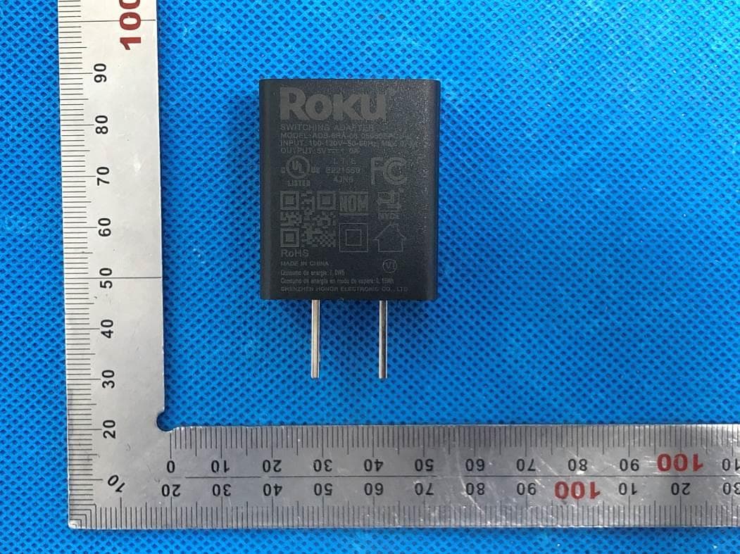
External Photos ALL VIEW OF EUT TOP VIEW OF EUT BOTTOM VIEW OF EUT FRONT VIEW OF EUT BACK VIEW OF EUT LEFT VIEW OF EUT RIGHT VIEW OF EUT VIEW OF EUT (PORT)-1 VIEW OF EUT (PORT)-2 VIEW OF ADAPTER
ID Label/Location Info
North of You, LLC 90 West Madison Ave Suite E-237 Belgrade, MT 59714 1-877-727-7362 www.witharsenal.com The following are instructions for accessing the e-labelingfor 2AOYX-NOYP3. 1.Open the phone application and select the SettingsIcon (Gear): North of You, LLC 90 West Madison Ave Suite E-237 Belgrade, MT 59714 1-877-727-7362 www.witharsenal.com 2.Scroll to the bottom and select Regulatory: North of You, LLC 90 West Madison Ave Suite E-237 Belgrade, MT 59714 1-877-727-7362 www.witharsenal.com 3.The following screen will appear:
Internal Photos
Internal Photos OPEN VIEW OF EUT INTERNAL VIEW-1 OF EUT INTERNAL VIEW-2 OF EUT INTERNAL VIEW-3 OF EUT INTERNAL VIEW-4 OF EUT INTERNAL VIEW-5 OF EUT INTERNAL VIEW-6 OF EUT INTERNAL VIEW-7 OF EUT INTERNAL VIEW-8 OF EUT INTERNAL VIEW-9 OF EUT Antenna VIEW OF BATTERY
RF Exposure Info
Page 1 of 49 SAR Test Report Report No.: AGC11160210304FH01 FCC ID : 2AOYX-NOYP3 APPLICATION PURPOSE : Original Equipment PRODUCT DESIGNATION : Arsenal 2 Pro BRAND NAME : Arsenal MODEL NAME : Robert APPLICANT : North of You, LLC DATE OF ISSUE : Apr. 08,2021 STANDARD(S) : IEEE Std. 1528:2013 FCC 47 CFR Part 2§2.1093:2013 IEEE Std C95.1 ™-2005 IEC 62209-1: 2016 REPORT VERSION : V1.0 Attestation of Global Compliance(Shenzhen) Co., Ltd. Report No.: AGC11160210304FH01 Page 2 of 49 Report Revise Record Report Version Revise Time Issued Date Valid Version Notes V1.0 / Apr. 08,2021 Valid Initial Release Report No.: AGC11160210304FH01 Page 3 of 49 Test Report Applicant Name North of You, LLC Applicant Address 90 West Madison Ave Suite E-237 Belgrade, MT 59714 United States of America Manufacturer Name North of You, LLC Manufacturer Address 90 West Madison Ave Suite E-237 Belgrade, MT 59714 United States of America Factory Name Computime Limited Factory Address 6/F, Building 20E, Phase 3, Hong Kong Science Park 20 Science Park East Avenue, Shatin, New Territories, Hong Kong Product Designation Arsenal 2 Pro Brand Name Arsenal Model Name Robert EUT Voltage DC3.7V by battery Applicable Standard IEEE Std. 1528:2013 FCC 47 CFR Part 2§2.1093:2013 IEEE Std C95.1 ™-2005 IEC 62209-1: 2016 Test Date Apr. 02,2021 to Apr. 07,2021 Report Template AGCRT- US -5G/SAR (2018-01-01) Note: The results of testing in this report apply to the product/system which was tested only. Prepared By Jack Gui (Project Engineer) Apr. 07,2021 Reviewed By Angela Li (Reviewer) Apr. 08,2021 Approved By Forrest Lei (Authorized Officer) Apr. 08,2021 Report No.: AGC11160210304FH01 Page 4 of 49 TABLE OF CONTENTS 1. SUMMARY OF MAXIMUM SAR VALUE ......................................................................................................... 5 2. GENERAL INFORMATION ............................................................................................................................... 6 2.1. EUT DESCRIPTION......................................................................................................................................... 6 3. SAR MEASUREMENT SYSTEM ........................................................................................................................ 7 3.1. THE DASY5 SYSTEM USED FOR PERFORMING COMPLIANCE TESTS CONSISTS OF FOLLOWING ITEMS .................... 7 3.2. DASY5 E-FIELD PROBE ................................................................................................................................. 8 3.3. DATA ACQUISITION ELECTRONICS DESCRIPTION ............................................................................................... 8 3.4. ROBOT .......................................................................................................................................................... 9 3.5. LIGHT BEAM UNIT .......................................................................................................................................... 9 3.6. DEVICE HOLDER .......................................................................................................................................... 10 3.7. MEASUREMENT SERVER ............................................................................................................................... 10 3.8. PHANTOM ................................................................................................................................................. 11 4. SAR MEASUREMENT PROCEDURE .............................................................................................................. 12 4.1. SPECIFIC ABSORPTION RATE (SAR) .............................................................................................................. 12 4.2. SAR MEASUREMENT PROCEDURE ................................................................................................................ 13 4.3. RF EXPOSURE CONDITIONS ......................................................................................................................... 15 5. TISSUE SIMULATING LIQUID ......................................................................................................................... 16 5.1. THE COMPOSITION OF THE TISSUE SIMULATING LIQUID..................................................................................... 16 5.2. TISSUE DIELECTRIC PARAMETERS FOR HEAD AND BODY PHANTOMS ............................................................... 16 5.3. TISSUE CALIBRATION RESULT ....................................................................................................................... 17 6. SAR SYSTEM CHECK PROCEDURE ........................................................................................................... 18 6.1. SAR SYSTEM CHECK PROCEDURES ............................................................................................................. 18 6.2. SAR SYSTEM CHECK ................................................................................................................................... 19 7. EUT TEST POSITION ...................................................................................................................................... 21 7.1. BODY WORN POSITION ................................................................................................................................ 21 8. SAR EXPOSURE LIMITS ............................................................................................................................... 22 9. TEST FACILITY .............................................................................................................................................. 23 10. TEST EQUIPMENT LIST .............................................................................................................................. 24 11. MEASUREMENT UNCERTAINTY ............................................................…
Text truncated - open the document above for the full version.
RF Exposure Info
CALIBRATION DATA PROBE CALIBRATION DATA DAE CALIBRATION DATA DIPOLE CALIBRATION DATA
Test Report
Page 1 of 110 Report No.: AGC11160210304FE06 FCC ID : 2AOYX-NOYP3 APPLICATION PURPOSE : Original Equipment PRODUCT DESIGNATION : Arsenal 2 Pro BRAND NAME : Arsenal MODEL NAME : Robert APPLICANT : North of You, LLC DATE OF ISSUE : May 28, 2021 STANDARD(S) TEST PROCEDURE(S) : FCC Part 15.407 KDB 789033 D02 v02r01 REPORT VERSION : V1.0 Attestation of Global Compliance (Shenzhen) Co., Ltd FCC Test Report Report No.: AGC11160210304FE06 Page 2 of 110 REPORT REVISE RECORD Report Version Revise Time Issued Date Valid Version Notes V1.0 / May 28, 2021 Valid Initial Release Report No.: AGC11160210304FE06 Page 3 of 110 TABLE OF CONTENTS 1. VERIFICATION OF CONFORMITY .................................................................................................................. 5 2. GENERAL INFORMATION .............................................................................................................................. 6 2.1. PRODUCT DESCRIPTION ........................................................................................................................ 6 2.2. TABLE OF CARRIER FREQUENCYS ....................................................................................................... 7 2.3. RELATED SUBMITTAL(S) / GRANT (S) .................................................................................................... 8 2.4. TEST METHODOLOGY ............................................................................................................................. 8 2.5. SPECIAL ACCESSORIES ......................................................................................................................... 8 2.6. EQUIPMENT MODIFICATIONS ................................................................................................................. 8 2.7. ANTENNA REQUIREMENT....................................................................................................................... 8 3. MEASUREMENT UNCERTAINTY ................................................................................................................... 9 4. DESCRIPTION OF TEST MODES ................................................................................................................. 10 5. SYSTEM TEST CONFIGURATION ................................................................................................................ 11 5.1. CONFIGURATION OF EUT SYSTEM ...................................................................................................... 11 5.2. EQUIPMENT USED IN EUT SYSTEM ..................................................................................................... 11 5.3. SUMMARY OF TEST RESULTS .............................................................................................................. 11 6. TEST FACILITY .............................................................................................................................................. 12 7. MAXIMUM CONDUCTED OUTPUT POWER ................................................................................................ 13 7.1. MEASUREMENT PROCEDURE ............................................................................................................. 13 7.2. TEST SET-UP........................................................................................................................................... 13 7.3. LIMITS AND MEASUREMENT RESULT .................................................................................................. 14 8. 6DB BANDWIDTH .......................................................................................................................................... 16 8.1. MEASUREMENT PROCEDURE ............................................................................................................. 16 8.1.1 -6DB BANDWIDTH MEASUREMENT PROCEDURE ............................................................................ 16 8.1.2 99% OCCUPIED BANDWIDTH ............................................................................................................. 16 8.2. TEST SET-UP (BLOCK DIAGRAM OF CONFIGURATION) .................................................................... 16 8.3. LIMITS AND MEASUREMENT RESULTS ............................................................................................... 17 9. EMISSION BANDWIDTH ............................................................................................................................... 32 9.1. MEASUREMENT PROCEDURE ............................................................................................................. 32 9.2. TEST SET-UP (BLOCK DIAGRAM OF CONFIGURATION) .................................................................... 32 9.3. LIMITS AND MEASUREMENT RESULTS ............................................................................................... 33 Report No.: AGC11160210304FE06 Page 4 of 110 10. MAXIMUM CONDUCTED OUTPUT AVERAGE POWER SPECTRAL DENSITY ...................................... 41 10.1 MEASUREMENT PROCEDURE ............................................................................................................ 41 10.2 TEST SET-UP (BLOCK DIAGRAM OF CONFIGURATION) ................................................................... 41 10.3 MEASUREMENT EQUIPMENT USED ................................................................................................... 41 10.4 LIMITS AND MEASUREMENT RESULT ................................................................................................. 41 11. CONDUCTED SPURIOUS EMISSION ......................................................................................................... 58 11.1. MEASUREMENT PROCEDURE............................................................................................................ 58 11.2. TEST SET-UP (BLOCK DIAGRAM OF CONFIGURATION) .................................................................. 58 11.3. MEA…
Text truncated - open the document above for the full version.
Test Report
Report No.: AGC11160210304FE06 Page 51 of 110 TEST PLOT OF SPECTRAL DENSITY FOR 5755MHz TEST PLOT OF SPECTRAL DENSITY FOR 5795MHz Report No.: AGC11160210304FE06 Page 52 of 110 802.11ac20 TEST RESULT TEST PLOT OF SPECTRAL DENSITY FOR 5180MHz TEST PLOT OF SPECTRAL DENSITY FOR 5200MHz Report No.: AGC11160210304FE06 Page 53 of 110 TEST PLOT OF SPECTRAL DENSITY FOR 5240MHz TEST PLOT OF SPECTRAL DENSITY FOR 5745MHz Report No.: AGC11160210304FE06 Page 54 of 110 TEST PLOT OF SPECTRAL DENSITY FOR 5785MHz TEST PLOT OF SPECTRAL DENSITY FOR 5825MHz Report No.: AGC11160210304FE06 Page 55 of 110 802.11ac40 TEST RESULT TEST PLOT OF SPECTRAL DENSITY FOR 5190MHz TEST PLOT OF SPECTRAL DENSITY FOR 5230MHz Report No.: AGC11160210304FE06 Page 56 of 110 TEST PLOT OF SPECTRAL DENSITY FOR 5755MHz TEST PLOT OF SPECTRAL DENSITY FOR 5795MHz Report No.: AGC11160210304FE06 Page 57 of 110 802.11ac80 TEST RESULT TEST PLOT OF SPECTRAL DENSITY FOR 5210MHz TEST PLOT OF SPECTRAL DENSITY FOR 5775MHz Report No.: AGC11160210304FE06 Page 58 of 110 11. CONDUCTED SPURIOUS EMISSION 11.1. MEASUREMENT PROCEDURE 1. Connect EUT RF output port to the Spectrum Analyzer through an RF attenuator 2, Set the EUT Work on the top, the middle and the bottom operation frequency individually. 3. Set SPA Trace 1 Max hold, then View. Note: The EUT was tested according to KDB 789033 for compliance to FCC 47CFR 15.407 requirements. 11.2. TEST SET-UP (BLOCK DIAGRAM OF CONFIGURATION) The same as described in section 8.2. 11.3. MEASUREMENT EQUIPMENT USED The same as described in section 6. 11.4. LIMITS AND MEASUREMENT RESULT LIMITS AND MEASUREMENT RESULT Applicable Limits Measurement Result Test channel Criteria -27dBm/MHz 5150MHz-5250MHz PASS All emissions shall be limited to a level of −27 dBm/MHz at 75 MHz or more above or below the band edge increasing linearly to 10 dBm/MHz at 25 MHz above or below the band edge, and from 25 MHz above or below the band edge increasing linearly to a level of 15.6 dBm/MHz at 5 MHz above or below the band edge, and from 5 MHz above or below the band edge increasing linearly to a level of 27 dBm/MHz at the band edge. 5725MHz-5850MHz PASS Report No.: AGC11160210304FE06 Page 59 of 110 FOR 802.11A20 MODULATION TEST PLOT OF OUT OF BAND EMISSIONS FOR MODULATION IN 5180MHz Report No.: AGC11160210304FE06 Page 60 of 110 Report No.: AGC11160210304FE06 Page 61 of 110 TEST PLOT OF OUT OF BAND EMISSIONS FOR MODULATION IN 5240MHz Report No.: AGC11160210304FE06 Page 62 of 110 Report No.: AGC11160210304FE06 Page 63 of 110 Report No.: AGC11160210304FE06 Page 64 of 110 TEST PLOT OF OUT OF BAND EMISSIONS FOR MODULATION IN 5745MHz Report No.: AGC11160210304FE06 Page 65 of 110 Report No.: AGC11160210304FE06 Page 66 of 110 TEST PLOT OF OUT OF BAND EMISSIONS FOR MODULATION IN 5825MHz Report No.: AGC11160210304FE06 Page 67 of 110 Report No.: AGC11160210304FE06 Page 68 of 110 Report No.: AGC11160210304FE06 Page 69 of 110 FOR 802.11N40 MODULATION TEST PLOT OF OUT OF BAND EMISSIONS FOR MODULATION IN 5190MHz Report No.: AGC11160210304FE06 Page 70 of 110 Report No.: AGC11160210304FE06 Page 71 of 110 TEST PLOT OF OUT OF BAND EMISSIONS FOR MODULATION IN 5230MHz Report No.: AGC11160210304FE06 Page 72 of 110 Report No.: AGC11160210304FE06 Page 73 of 110 Report No.: AGC11160210304FE06 Page 74 of 110 TEST PLOT OF OUT OF BAND EMISSIONS FOR MODULATION IN 5755MHz Report No.: AGC11160210304FE06 Page 75 of 110 Report No.: AGC11160210304FE06 Page 76 of 110 TEST PLOT OF OUT OF BAND EMISSIONS FOR MODULATION IN 5795M Report No.: AGC11160210304FE06 Page 77 of 110 Report No.: AGC11160210304FE06 Page 78 of 110 Report No.: AGC11160210304FE06 Page 79 of 110 FOR 802.11AC80 MODULATION TEST PLOT OF OUT OF BAND EMISSIONS FOR MODULATION IN 5210MHz Report No.: AGC11160210304FE06 Page 80 of 110 Report No.: AGC11160210304FE06 Page 81 of 110 TEST PLOT OF OUT OF BAND EMISSIONS FOR MODULATION IN 5775MHz Report No.: AGC11160210304FE06 Page 82 of 110 Report No.: AGC11160210304FE06 Page 83 of 110 Note: All the 20MHz bandwidth modulation had been tested, the 802.11a20 was the worst case and record in his test report. All the 40MHz bandwidth modulation had been tested, the 802.11N40 was the worst case and record in his test report. ll the 80MHz bandwidth modulation had been tested, the 802.11AC80 was the worst case and record in his test report. Report No.: AGC11160210304FE06 Page 84 of 110 12. RADIATED EMISSION 12.1. MEASUREMENT PROCEDURE 1. The EUT was placed on the top of the turntable 0.8 or 1.5 meter above ground. The phase center of the receiving antenna mounted on the top of a height-variable antenna tower was placed 3 meters far away from the turntable. 2. Power on the EUT and all the supporting units. The turntable was rotated by 360 degrees to determine the position of the highest radiation. 3. The height of the broadband receiving antenna was varied between one meter and four meters above ground to find the maximum emissions field strength of both horizontal and vertical polarization. 4. For each suspected emissions, the antenna tower was scan (from 1 M to 4 M) and then the turntable was rotated (from 0 degree to 360 degrees) to find the maximum reading. 5. Set the test-receiver system to Peak or CISPR quasi-peak Detect Function with specified bandwidth under Maximum Hold Mode. 6. For emissions above 1GHz, use 1MHz RBW and 3M VBW for peak reading. Place the measuremen…
Text truncated - open the document above for the full version.
Contact Information
Applicant
Phillip Karls
Technical Contact
Test Firm
Attestation of Global Compliance (Shenzhen) Co., LDoris Li
[email protected]+86-755-25234088
Technical Specifications
| # | Rule Parts | Frequency Range | Power Output |
|---|---|---|---|
| 2 | 15E | 5.75 GHz - 5.83 GHz | 20.70 mW |
Other Applications from North of You, LLC
2AOYX-NOYP2
Dec 19, 2020Arsenal 2 with Bluetooth & 2.4G & 5G WiFi
Equipment Class
DTS - Digital Transmission System