2APN5MINIR2Wi-Fi Smart Switch with DIY Mode
Shenzhen Sonoff Technologies Co., Ltd.
Click to zoom
Application Details
- Equipment Class
- DTS - Digital Transmission System
- Date of Grant
- Aug 04, 2020
- Application Purpose
- Original Equipment
- Date of Application
- Aug 04, 2020
- Equipment Note
- Wi-Fi Smart Switch with DIY Mode
- Frequency Range
- 2412.00000000 - 2462.00000000
- Country
- China
Documents & Files
Document Text
Text extracted from the exhibit documents filed with the FCC. Open a document above to read the original.
Users Manual
Wi-Fi Smart Switch with DIY Mode User manual V1.0 MINIR2 ·中 文 ------------1 - 4 ·English ------- 5-8 · Español -----14-18 · Français --------19-23 · Deutsch ---------9-13 · Italiano------24-28 ·Русский язык-- 29-33 ·Português---34-38 ·FCC Warning------- 39 N In LOut S2 L In S1 N In N In LOut S2 L In S1 N In Shenzhen Sonoff Technologies Co.,Ltd. 中 文 使用说明 设备安装、故障维修请由专业资质电工操作,以免发生触电危险!设备在正常使用的情 况下不可触碰到。 1.断电 ONOFF ONOFF ON OFF L In N In 100-240V AC L L1 L2 SPDT L L1 L2 SPDT 2.接线 确保零火线接入无误。 S1/S2接或不接机械开关两端(不支持自动回弹的机械开关),设备都可以正常使用。 为确保安全,请勿接入零火线等强电。 eWeLink 3. 下载“易微联”APP 1 N In LOut S2 L In S1 N In L In N In 4.上电 通电后,设备首次使用,默认进入快速配网模式(Touch)。Wi-Fi指示灯呈“两短一长闪烁”。 三分钟内没有进行配网,设备将退出快速模式。如需再次进入,长按配对按钮5秒直到 Wi-Fi指示灯呈两短一长闪烁即可。 5.添加设备 快速添加 添加设备 WIFI 类设备,可使用该模式添加(请确 认)设备处于配网状态) 扫码添加 GSM 类设备和附带二维码的设备, 可使用该模式添加 声波添加 支持声波配对设备,可使用该模式添加 点击“+”,选择“快速添加”,再根据app提示进行操作。 如使用快速添加模式配网失败,请使用“兼容模式(AP)”进行配对。 兼容模式(AP) 1 长按配对按钮5秒直到Wi-Fi指示灯呈“两短一长闪烁”状态,松开。再次长按配对按钮 5秒直到Wi-Fi指示灯呈“快闪”状态,此时设备进入兼容模式。 2 在app界面,点击“+”,选择“兼容模式”。 Android设备: 只需输入Wi-Fi密码,点击“下一步”等待配对完成。 i O S设 备: 先把移动设备连接上Wi-Fi账号为:ITEAD-******,密码为:12345678,然后回到 “易微联”app,点击“下一步”,等待配对完成。 Shenzhen Sonoff Technologies Co.,Ltd. 中 文 2 N In LOut S2 L In S1 N In 产品介绍 Wi-Fi信号指示灯(蓝色) 电源指示灯(红色) 配对按钮/手动开关 Shenzhen Sonoff Technologies Co.,Ltd. 中 文 设备重量<1Kg,建议安装高度<2米。 Wi-Fi信号指示灯状态说明 快速闪烁 快速配网模式 两短一长闪烁 常亮 兼容模式(AP) 设备已连接 快闪一下 找不到路由 快闪二下 连接上路由,但没连上外网 快闪三下 升级中 状态描述 指示灯状态 产品参数 型号 最大输入 最大输出 支持平台 Wi-Fi 材料 产品规格 MINIR2 100-240V AC 50/60Hz 10A 100-240V AC 50/60Hz 10A IEEE 802.11 b/g/n 2.4GHz PC V0 42.6x42.6x20mm Android & iOS 3 恢复出厂设置 长按配对按钮5秒直到Wi-Fi指示灯呈两短一长闪烁再松开, 此时设备重置成功,默认进入快速配网模式(Touch)。 N In LOutS2 L In S1 N In 更换新的网络环境使用时,需要恢复出厂设置,再重 新进行网络连接。 Shenzhen Sonoff Technologies Co.,Ltd. 中 文 常见问题 2. 蓝灯1秒快闪两下:说明设备已连接到了Wi-Fi 但没有连上外网。 请确认您的Wi-Fi当前连接外网是否稳定、正常。如时好时坏,频繁出现这种双闪情况,说明您 的网络不稳定,并非产品原因。 问:设备添加成功后,显示离线,无法控制? 答:设备刚添加成功后,需要1-2分钟时间连接您的路由器并连网。如果长时间还是显示不 在线,请根据Wi-Fi指示灯的状态来判断: 1. 蓝灯1秒快闪一下:说明设备没有连上您的Wi-Fi。 ① 可能是Wi-Fi密码输入不正确. ② 可能是设备离您的路由器太远,信号太弱,或环境有干扰。请先将设备靠近路由器,如无改 善,重新添加一遍. ③ 设备不能识别5G的Wi-Fi,请选择2.4G的Wi-Fi重新添加. ④ 检查您的路由器后台是否开启MAC地址过滤,如有,请关闭。 如果以上均尝试不能解决,请用一部手机开启个人热点,尝试重新添加。 4 产品特点 用您的智能手机在任何地方打开或关闭家里的设备,设置定时开/关、分享给您的家人控制 等等。 远程控制 智能定时/延时 语音控制分享功能 无需交换机 局域网功能 同步状态 智能场景 添加摄像头 上电状态设置 1.Power off ONOFF ONOFF ON OFF N In LOut S2 L In S1 N In L In N In 100-240V AC L L1 L2 SPDT L L1 L2 SPDT 2.Wiring instruction 3. Download APP Shenzhen Sonoff Technologies Co.,Ltd. English Operating Instruction To avoid electric shocks, please consult the dealer or a qualified professional for help when installing and repairing! Please do not touch the switch during use. Make sure the neutral wire and live wire connection is correct. S1/S2 can connect with the rocker light switch (the self-return rocker light switch is not supported) or doesn't connect. To ensure safety, do not connect the neutral wire and live wire to it. eWeLink eWeLink 5 N In LOut S2 L In S1 N In L In N In 4.Power on 5.Add the device After powering on, the device will enter the quick pairing mode (Touch) during the first use. The Wi-Fi LED indicator changes in a cycle of two short and one long flash and release. The device will exit the quick pairing mode (Touch) if not paired within 3mins. If you want to enter this mode, please long press the manual button for about 5s until the Wi-Fi LED indicator changes in a cycle of two short and one long flash and release. Sound Pairing Add device in this mode if your devic e support this feature. Scan QR code GSM devices and devices with QR co de can be added in this mode. Quick Pairing WIFI devices can be added in this mo de(make sure the device is in pairing mode). Add Device Tap “+” and select “Quick Pairing”, then operate following the prompt on the APP. 1 Compatible Pairing Mode If you fail to enter Quick Pairing Mode (Touch), please try “Compatible Pairing Mode ” to pair. Long press Pairing button for 5s until the Wi-Fi LED indicator changes in a cycle of two short flashes and one long flash and release. Long press Pairing button for 5s again until the Wi-Fi LED indicator flashes quickly. Then, the device enters Compatible Pairing Mode. 2 Tap “+” and select “ Compatible Pairing Mode ” on APP. For Android system: Enter Wi-Fi password and tap “Next”. Be patient until pairing completes. For iOS system: Select Wi-Fi SSID with ITEAD-****** and enter the password 12345678, and then go back to eWeLink APP and tap “Next”. Be patient until pairing completes. Shenzhen Sonoff Technologies Co.,Ltd. English 6 N In LOut S2 L In S1 N In MINIR2 100-240V AC 50/60Hz 10A Max 100-240V AC 50/60Hz 10A Max IEEE 802.11 b/g/n 2.4GHz PC V0 42.6x42.6x20mm Android & iOS Wi-Fi Model Input Output Operating systems Dimension Material Wi-Fi LED indicator(Blue) Pairing button Manual switch On/off LED indicator(Red) The device weight is less than 1 kg. The installation height of less than 2 m is recommended. Specifications Product Introduction Wi-Fi LED indicator status instruction Status instruction Wi-Fi LED indicator status Quick Pairing ModeFlashes (one long and two short) Device is connected successfully Keeps on Flashes quickly Compatible Pairing Mode Unable to discover the router Upgrading Connect to the router but fail to connect to Wi-Fi Flashes quickly once Flashes quickly three times Flashes quickly twice Shenzhen Sonoff Technologies Co.,Ltd. English 7 N In LOut S2 L In S1 N In Camera Feature Common Problems Q: Why my device stays “Offline”? A: The newly added device needs 1 – 2mins to connect Wi-Fi and network. If it stays offline for a long time, please judge these problems by the blue Wi-Fi indicator status: 1. The blue Wi-Fi indicator quickly flashes once per second, which means that the switch failed to connect your Wi-Fi: ① Maybe you have entered a wrong Wi-Fi password. ② Maybe there's too much distance between the switch your router or the environment causes interference, consider getting close to the router. If failed, please add it again. ③ The 5G Wi-Fi network is not supported and only supports the 2.4GHz wireless netwo…
Text truncated - open the document above for the full version.
Cover Letter(s)
QA-FR- 170-B Shenzh en Sonoff Technologies Co.,Ltd. ADD: 1001, BLDG8, Lianhua Industrial Park, shenzhen, GD, China TEL: 0755-27955416 FAX: 0755-27955416 E-mail: [email protected] FCC Authorization Date: 2020-07-15 FEDERAL COMMUNICATIONS COMMISSION Authorization and Evaluation Division 7435 Oakland Mills Road Columbia, MD 21046 Subject: Agent Authorization To whom it may concern: We , Shenzhen Sonoff Technologies Co.,Ltd., Hereby authorizes Bay Area Compliance Laboratories Corporation to act on its behalf in all matters relating to application for Equipment authorization, including the signing of all documents relating to these matters. All acts carried out by Bay Area Compliance Laboratory Corporation on our behalf shall have the same effect as our own action. We, the undersigned, hereby certify that we are not subject to a denial of federal benefits, that includes FCC benefits, pursuant to Section 5301 of the Anti-Drug Abuse Act of 1988, 21 U.S.C. 862. This authorization is valid until further written notice from the applicant. Sincerely Yours, Client’s signature Printed Name: Jerry Shi Title: Manager
Cover Letter(s)
QA-FR-171-A Shenzhen Sonoff Technologies Co.,Ltd. Add: 1001, BLDG8, Lianhua Industrial Park, shenzhen, GD, China Tel: 0755-27955416 Fax: 0755-27955416 Email: [email protected] FCC Confidential Authorization Date:2020-07-15 FEDERAL COMMUNICATIONS COMMISSIONS Authorization and Evaluation Division 7435 Oakland Mills Road Columbia, MD 21046 Subject: Confidentiality Request regarding application for certification of FCC ID: 2APN5MINIR2 In accordance with Sections 0.457 and 0.459 of the Commission’s Rules, Shenzhen Sonoff Technologies Co.,Ltd. hereby requests long-term confidential treatment of information accompanying this application as outlined below: •Block Diagram •Schematics •Operation Description The above materials contain proprietary and confidential information not customarily released to the public. The public disclosure of these materials provides unjustified benefits to its competitors in the market. Sincerely, Signature: Jerry Shi Manager
External Photos
EXHIBIT B - EUT EXTERNAL PHOTOGRAPHS
Internal Photos
EXHIBIT C - EUT INTERNAL PHOTOGRAPHS
RF Exposure Info
Bay Area Compliance Laboratories Corp. (Dongguan) Report No.: RDG200622009-00B Page 11 of 50 FCC §15.247 (i) & §1.1310 & §2.1091- MAXIMUM PERMISSIBLE EXPOSURE (MPE) Applicable Standard According to subpart 15.247(i)and subpart §1.1310, systems operating under the provisions of this section shall be operated in a manner that ensures that the public is not exposed to radio frequency energy level in excess of the Commission’s guidelines. Limits for Maximum Permissible Exposure (MPE) (§1.1310, §2.1091) (B) Limits for General Population/Uncontrolled Exposure Frequency Range (MHz) Electric Field Strength (V/m) Magnetic Field Strength (A/m) Power Density (mW/cm 2 ) Averaging Time (minutes) 0.3–1.34 614 1.63 *(100) 30 1.34–30 824/f 2.19/f *(180/f²) 30 30–300 27.5 0.073 0.2 30 300–1500 / / f/1500 30 1500–100,000 / / 1.0 30 f = frequency in MHz; * = Plane-wave equivalent power density; According to §1.1310 and §2.1091 RF exposure is calculated. Calculation formula: Prediction of power density at the distance of the applicable MPE limit S = PG/4R² = power density (in appropriate units, e.g. mW/cm 2 ); P = power input to the antenna (in appropriate units, e.g., mW); G = power gain of the antenna in the direction of interest relative to an isotropic radiator, the power gain factor, is normally numeric gain; R = distance to the center of radiation of the antenna (appropriate units, e.g., cm); Calculated Data: Mode Frequency (MHz) Antenna Gain Conducted output power including Tune- up Tolerance Evaluation Distance (cm) Power Density (mW/cm 2 ) MPE Limit (mW/cm 2 ) (dBi) (numeric)(dBm)(mW) WLAN 2412-24622 1.58 24251.19 20.00 0.08 1.0 Result: The device meet FCC MPE at 20 cm distance
Test Report
FCC PART 15.247 TEST REPORT For Shenzhen Sonoff Technologies Co.,Ltd. 1001, BLDG8, Lianhua Industrial Park, shenzhen, GD, China Report Type: Original Report Product Name: Wi-Fi Smart Switch with DIY Mode Re port Number: RDG200622009-00B Re port Date: 2020-07-06 Reviewed By: Ivan Cao Assistant Manager Test Laboratory: Bay Area Compliance Laboratories Corp. (Dongguan) No.69 Pulongcun, Puxinhu Industry Area, Tangxia, Dongguan, Guangdong, China Tel: +86-769-86858888 Fax: +86-769-86858891 www.baclcorp.com.cn FCC ID: 2APN5MINIR2 Bay Area Compliance Laboratories Corp. (Dongguan) Report No.: RDG200622009-00B Page 2 of 50 TABLE OF CONTENTS GENERAL INFORMATION ....................................................................................................................................... 4 PRODUCT DESCRIPTION FOR EQUIPMENT UNDER TEST (EUT) ..................................................................................... 4 OBJECTIVE ................................................................................................................................................................... 4 RELATED SUBMITTAL(S)/GRANT(S) ............................................................................................................................. 4 TEST METHODOLOGY .................................................................................................................................................. 4 MEASUREMENT UNCERTAINTY .................................................................................................................................... 5 TEST FACILITY ............................................................................................................................................................. 5 DECLARATIONS ............................................................................................................................................................ 5 SYSTEM TEST CONFIGURATION .......................................................................................................................... 6 DESCRIPTION OF TEST CONFIGURATION ...................................................................................................................... 6 EUT EXERCISE SOFTWARE .......................................................................................................................................... 6 EQUIPMENT MODIFICATIONS ....................................................................................................................................... 8 LOCAL SUPPORT EQUIPMENT LIST AND DETAILS ........................................................................................................ 8 SUPPORT CABLE LIST AND DETAILS ............................................................................................................................ 8 BLOCK DIAGRAM OF TEST SETUP ................................................................................................................................ 9 SUMMARY OF TEST RESULTS ............................................................................................................................. 10 FCC §15.247 (i) & §1.1310 & §2.1091- MAXIMUM PERMISSIBLE EXPOSURE (MPE) ....................................... 11 APPLICABLE STANDARD ............................................................................................................................................ 11 FCC §15.203 - ANTENNA REQUIREMENT ........................................................................................................... 12 APPLICABLE STANDARD ............................................................................................................................................ 12 ANTENNA CONNECTOR CONSTRUCTION .................................................................................................................... 12 FCC §15.207 (a) – AC LINE CONDUCTED EMISSIONS ..................................................................................... 13 APPLICABLE STANDARD ............................................................................................................................................ 13 EUT SETUP ................................................................................................................................................................ 13 EMI TEST RECEIVER SETUP ....................................................................................................................................... 13 TEST PROCEDURE ...................................................................................................................................................... 14 CORRECTED AMPLITUDE & MARGIN CALCULATION ................................................................................................. 14 TEST EQUIPMENT LIST AND DETAILS ......................................................................................................................... 14 TEST DATA ................................................................................................................................................................ 15 FCC §15.209, §15.205 & §15.247(d) - SPURIOUS EMISSIONS ............................................................................. 17 APPLICABLE STANDARD ............................................................................................................................................ 17 EUT SETUP ................................................................................................................................................................ 17 EMI TEST RECEIVER & SPECTRUM ANALYZER SETUP .............................................................................................. 18 TEST PROCEDURE ...................................................................................................................................................... 18 CORRECTE…
Text truncated - open the document above for the full version.
Test Setup Photos
EXHIBIT D - TEST SETUP PHOTOGRAPHS Conducted Emissions Front View Conducted Emissions Side View Radiated Emission Below 1GHz View Radiated Emission Above 1GHz View
Contact Information
Applicant
Freddie Duan(Manager)
Test Firm
Bay Area Compliance Laboratories Corp.(Dongguan)David Zhang
[email protected]0086 0769 86858888
Technical Specifications
| # | Rule Parts | Frequency Range | Power Output |
|---|---|---|---|
| 1 | 15C | 2.41 GHz - 2.46 GHz | 248.00 mW |
Other Applications from Shenzhen Sonoff Technologies Co., Ltd.
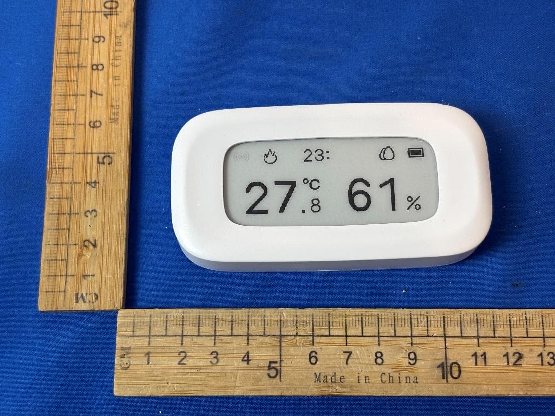
2APN5-SNZB02UL
Aug 12, 2026Zigbee Temperature Humidity Sensor
Equipment Class
DTS - Digital Transmission System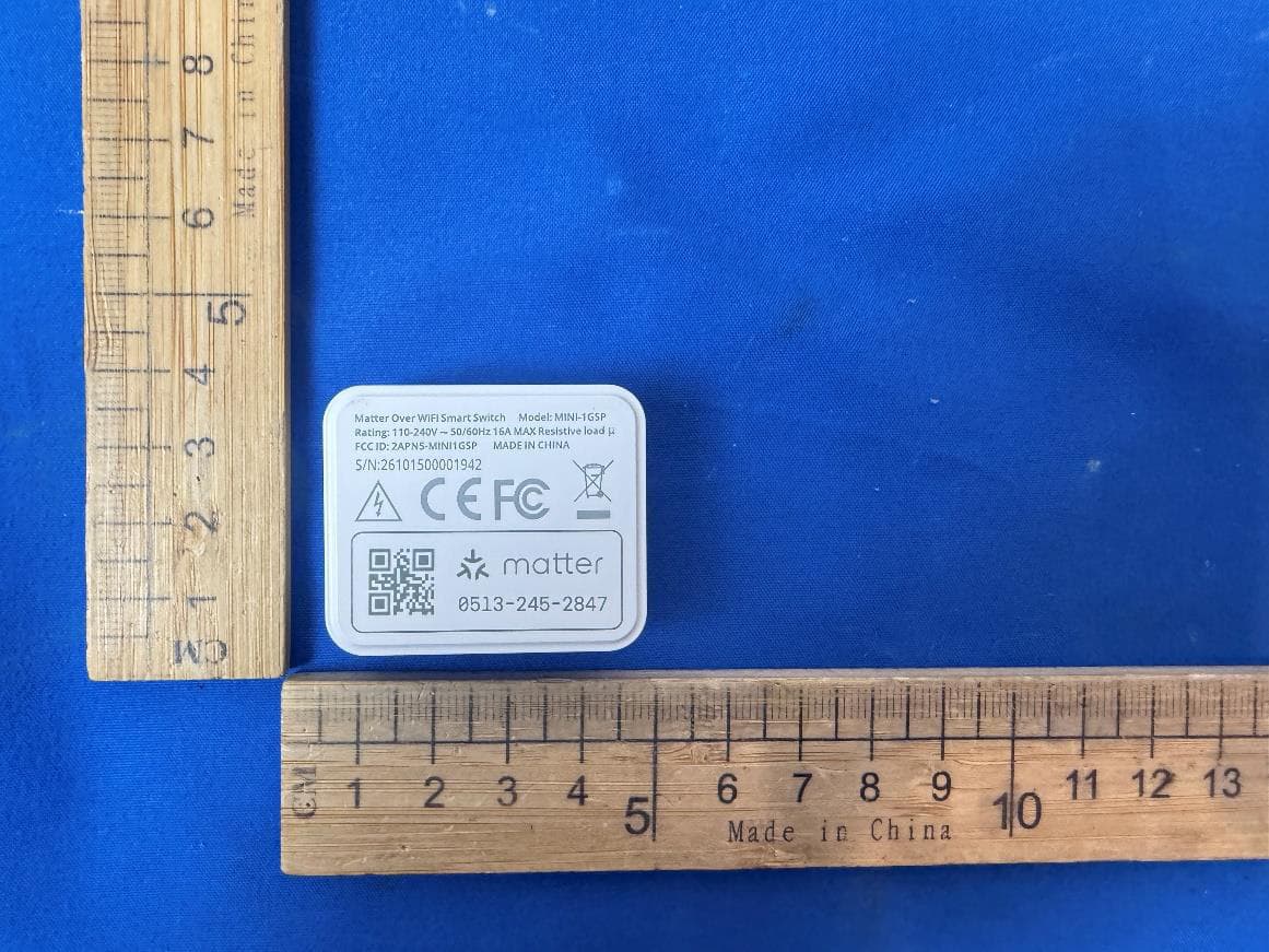
2APN5-MINI1GSP
Jul 15, 2026Matter Over WiFi Smart Switch
Equipment Class
DTS - Digital Transmission System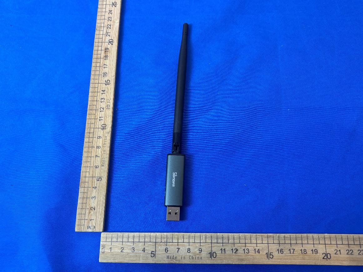
2APN5-DONGLEPP10
Jul 13, 2026Zigbee/Thread USB Dongle
Equipment Class
DTS - Digital Transmission System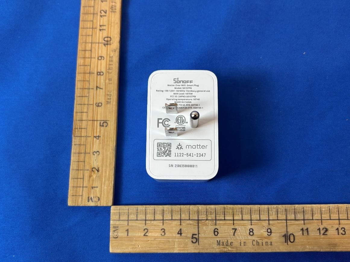
2APN5-S61STPB
Jul 10, 2026Matter Over WiFi Smart Plug
Equipment Class
DTS - Digital Transmission System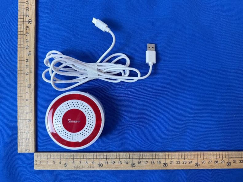
2APN5-SNZB09P
Jul 08, 2026Zigbee Siren
Equipment Class
DTS - Digital Transmission System