2APN5MINIR4Wi-Fi Smart Switch
Shenzhen Sonoff Technologies Co., Ltd.
Click to zoom
Application Details
- Equipment Class
- DTS - Digital Transmission System
- Date of Grant
- May 04, 2023
- Application Purpose
- Original Equipment
- Date of Application
- May 04, 2023
- Equipment Note
- Wi-Fi Smart Switch
- Frequency Range
- 2402.00000000 - 2480.00000000
- Country
- China
Documents & Files
Document Text
Text extracted from the exhibit documents filed with the FCC. Open a document above to read the original.
Users Manual
·中 文 ----------1 - 7· English ----------8 - 14· Warning ----------15 - 16 MINI Extreme Wi-Fi Smart Switch 产品介绍 设备重量<1Kg,建议安装高度<2米。 1 按键 接线端口 网络指示灯 信号指示灯状态说明 指示灯状态 状态说明 蓝灯呈两短一长闪烁蓝牙配网模式 设备在线蓝色常亮 功能特点 MINI Extreme紧凑小巧的机身,能够安装在开关暗盒中且最大支持10A负载,使普通开关变为智 能开关。安全且智能,也可在智能场景中联动其他设备,实现你的家庭自动化。 设备安装 1. 断电 设备安装、故障维修请由专业资质电工操作。切勿在设备通电时进行接线操作或触碰到接线 端子,以免发生触电危险! 2 语音控制 智能场景 远程控制 通电反应 局域网控制 群组控制 智能定时/延时 点动模式 配对至易微联App 1. 下载易微联App 请前往应用商店、Google Play Store或Apple App Store搜索"易微联"进行下载。 2. 接线 1. S1、S2 接或不接开关,设备都可通过自动化或App来控制。 2. 禁止将S1连接零线、地线等强电, 禁止将S2连接火线、零线、地线等强电,以免损坏设备, 造成危险。 3. 确保线路接入无误。 3 3.添加设备 点 击“+”,选 择“蓝牙配网”,再根据 App 提示进行操作。 2. 上电 通电后, 设备首次使用, 默认进入蓝牙配网模式。 网络指示灯呈“两短一长闪烁”。 10分钟内没有进行配网,设备将退出蓝牙配网模式。如需再次进入,长按设备按钮5秒直到 网络指示灯呈两短一长闪烁即可。 4 添加设备 快速添加 扫码添加 蓝牙配网 适用于大部分易微联生态设备 适用于GSM类、 附带二维码的 设备 声波配对 适用于摄像头等 支持声波配对的 设备 适用于WiFi+蓝牙双模、蓝牙设备 所有设备 添加轻智能子设备 将MINI Extreme安装在暗盒中 进入 eWeLink App 设备设置页面,选择“轻智能子设备”再 点 击“添加”,然后触发子设备,即可添 加成功。 5 设备设置轻智能子设备 添加 快捷设置 位置管理 分享设备 创建群组 小程序控制 局域网控制 设备设置 网络指示灯 轻智能子设备 0/8 在 eWeLink App 设备设置界面选择 “WiFi设置” 进行更换。 产品参数 产品型号 输入 输出 最大功率 Wi-Fi 工作温度 工作湿度 外壳材料 产品规格 MINIR4 100-240V ~ 50/60Hz 10A Max 100-240V ~ 50/60Hz 10A Max 2400W IEEE 802.11b/g/n 2.4GHz -10°C-40°C 5%-95%RH,无冷凝 PC V0 39.5x33x16.8mm 更换设备网络 6 常见问题 1. Wi-Fi设备与易微联App配对失败 1、 确保设备进入配对模式. 10分钟内设备没有配对成功,则自动退出配对模式。 2、 请开启定位服务以及允许获取定位权限 配网前,请先开启手机的定位服务并允许获取定位权限。位置信息权限用于获取Wi-Fi列表信息, 如果“禁用”手机定位服务,设备将无法添加。 在 eWeLink App 端“删除设备”,设备即恢复出厂设置。 恢复出厂设置 3、 确保Wi-Fi运行在2.4GHz频段。 4、 确保正确输入Wi-Fi网络名称和密码,且没有包含特殊字符。 密码错误是常见的配对失败原因。 5、 配对时为了确保良好的信号传输,请将设备靠近路由器。 2. LED指示灯连续闪烁两次,服务器连接失败 1、 确保网络连接正常。你可以通过手机或者电脑连接网络。如果连接失败,请检查网络。 2、 路由器承载力较低,连接到路由器的设备超过最大值。请查看你的路由器可以连接的最大设 备数量。如果超过最大值,请删除个别设备或者更换一个承载力较高的路由器再次连接。 如果以上方法均无法解决此问题,请在易微联APP上通过“帮助&反馈”提交你的问题。 7 3. Wi-Fi设备“离线”问题 1、 路由器连接失败 2、 输入不正确的Wi-Fi网络名称和密码 3、 Wi-Fi网络名称和密码包含特殊字符。例如,我们的系统无法识别希伯来语和阿拉伯语字符, 导致Wi-Fi连接失败 4、 路由器承载力较低 5、 Wi-Fi信号太弱。路由器和设备间隔太远,或者路由器与设备之前有障碍物导致信号无法传 输。 English Button Wiring ports Network indicator Product introduction 8 Instruction of LED indicator status LED indicator status Status instruction Blue LED indicator flashes (one long and two short) Bluetooth pairing mode Device is onlineBlue LED indicator keeps on The device weight is less than 1kg, and the recommended installation height is less than 2m. English Features MINI Extreme is compact and tiny enough to be installed in the mounted box, and it supports loads of up to 10A, enable to transform your ordinary switch into a smart switch. Safe and smart, allows you to set smart scenes with other smart devices to automate your home. Voice Control Smart Scene Remote Control Power-on State LAN Control Group Control Timer Schedule Inching Mode Installation 1. Power off Please install and maintain the device by a professional electrician. To avoid electric shock hazard, do not operate any connection or contact the terminal connector while the device is powered on! 9 English Pair with eWeLink App 1. Download the eWeLink App Please download the "eWeLink" App from Google Play Store or Apple App Store. 2. Wiring instruction Before installing the device, please install an air switch as the protective device (Air switch: 10A/250V). 1No matter S1 and S2 are connected or left idle to the external switch, this device canbe controlled by automation or the App. 2To avoid damaging the equipment and causing danger, it is forbidden to connect S1 to strong electricity such as neutral wire or earth wire or to connect S2 to strong electricity such as live wire, neutral wire, earth wire and etc. 3Make sure all wires are connected correctly. 10 English 3.Add device Tap “+” and select “Bluetooth Pairing”, then operate following the prompt on the App. 2. Power on After powering on, the device will enter the Bluetooth Pairing Mode defaulted during the first use, and the Network indicator flashes in a cycle of two short and one long. The device will exit the Bluetooth Pairing Mode if not been paired within 10mins. If you want to enter this mode again, please long press the button for 5s until the Network indicator flashes in a cycle of two short and one long and then release. 11 English Add eWeLink-Remote Sub-devices Install the MINI Extreme in the mounting box Enter the Device Settings page on the eWeLink App, select "eWeLink-Remote sub-devices" and tap "Add", then trigger the sub-device to add it successfully. 12 English Change the device's network by "Wi-Fi Settings" in the "Device Settings" page on the eWeLink App. Specifications Model Input Output Max. power Wi-Fi Working temperature Working humidity Casing material Dimension MINIR4 100-240V ~ 50/60Hz 10A Max 100-240V ~ 50/60Hz 10A Max 2400W IEEE 802.11b/g/n 2.4GHz -10°C-40°C 5%-95% RH, non-condensing PC V0 39.5x33x16.8mm Device Network Changing FAQ (Frequently Asked Questions) 1. Fail to pair Wi-Fi devices with the eWeLink App 1Make sure the device is in pairing mode. The device will automatically exit the pairing mode if it is not paired within 10mins. 2Please enable location service and allow access to location permission. Before connecting Wi-Fi network, please enable the location service and allow access to the location permission. Location information permission is used to obtain Wi-Fi list information, if you "disable" the location service, the device cannot be paired. Reset the device to factory settings by "Delete device" on the eWeLink App. Factory Reset 13 14 English 3Make sure your Wi-Fi works on 2.4GHz band. 4Make sure to enter the Wi-Fi SSID and password correctly without special characters. Incorrect password is a common cause of pairing failure. 5To ensure good signal transmission while pairing, please place the device close to the router. 2. The LED indicator flashes twice on repeated means the server fails to connect. 1Make sure the networking is normal. Check the internet works well by connecting your phone or PC. If fail to connect, please check the availability of the Internet connection. 2.With the low load capacity of the router, the connected devices exceed the router's maximum load capacity. Ple…
Text truncated - open the document above for the full version.
Cover Letter(s)
QA-FR-171 -A
External Photos
EXHIBIT B - EUT EXTERNAL PHOTOGRAPHS EUT
ID Label/Location Info
33.75 mm 28.05 mm AUTO AUTO 2.82 mm 4.59 mm 3.14 mm 3.03 mm 33 mm
Internal Photos
EXHIBIT C - EUT INTERNAL PHOTOGRAPHS chip chip chip Antenna Antenna
RF Exposure Info
China Certification ICT Co., Ltd (Dongguan) Report No.: CR221263055-00C Page 42 of 43 5. RF EXPOSURE EVALUATION 5.1 MPE-Based Exemption 5.1.1 Applicable Standard According to §1.1307(b)(3)(i) (C) Or using Table 1 and the minimum separation distance (R in meters) from the body of a nearby person for the frequency (f in MHz) at which the source operates, the ERP (watts) is no more than the calculated value prescribed for that frequency. For the exemption in Table 1 to apply, R must be at least λ/2π, where λ is the free-space operating wavelength in meters. If the ERP of a single RF source is not easily obtained, then the available maximum time-averaged power may be used in lieu of ERP if the physical dimensions of the radiating structure(s) do not exceed the electrical length of λ/4 or if the antenna gain is less than that of a half-wave dipole (1.64 linear value). Table 1 to § 1.1307(b)(3)(i)(C) - Single RF Sources Subject to Routine Environmental Evaluation RF Source frequency (MHz) Threshold ERP (watts) 0.3-1.34 1,920 R 2 . 1.34-30 3,450 R 2 /f 2 . 30-300 3.83 R 2 . 300-1,500 0.0128 R 2 f. 1,500-100,000 19.2R 2 . 5.1.2 Measurement Result Operation Modes Frequency (MHz) λ/2π (mm) Distance (mm) Exemption ERP Maximum Conducted Power including Tune-up Tolerance (dBm) Antenna Gain (dBi) ERP (dBm) MPE- Based Exemption (mW)(dBm) WLAN 2.4G 2412-2462 19.80 200 768 28.85 16.00 0.77 14.62 Compliant BLE 2402-480 19.89 200 768 28.85 0.00 0.77 -1.38 Compliant Note: The WLAN and Bluetooth/BLE can`t transmit simultaneously. The Maximum Conducted Power including Tune-up Tolerance was declared by manufacturer. Result: The device compliant the MPE-Based Exemption at 20cm distances.
RF Exposure Info
China Certification ICT Co., Ltd (Dongguan) Report No.: CR221263055-00A Page 58 of 59 5. RF EXPOSURE EVALUATION 5.1 MPE-Based Exemption 5.1.1 Applicable Standard According to §1.1307(b)(3)(i) (C) Or using Table 1 and the minimum separation distance (R in meters) from the body of a nearby person for the frequency (f in MHz) at which the source operates, the ERP (watts) is no more than the calculated value prescribed for that frequency. For the exemption in Table 1 to apply, R must be at least λ/2π, where λ is the free-space operating wavelength in meters. If the ERP of a single RF source is not easily obtained, then the available maximum time-averaged power may be used in lieu of ERP if the physical dimensions of the radiating structure(s) do not exceed the electrical length of λ/4 or if the antenna gain is less than that of a half-wave dipole (1.64 linear value). Table 1 to § 1.1307(b)(3)(i)(C) - Single RF Sources Subject to Routine Environmental Evaluation RF Source frequency (MHz) Threshold ERP (watts) 0.3-1.34 1,920 R 2 . 1.34-30 3,450 R 2 /f 2 . 30-300 3.83 R 2 . 300-1,500 0.0128 R 2 f. 1,500-100,000 19.2R 2 . 5.1.2 Measurement Result Operation Modes Frequency (MHz) λ/2π (mm) Distance (mm) Exemption ERP Maximum Conducted Power including Tune-up Tolerance (dBm) Antenna Gain (dBi) ERP (dBm) MPE- Based Exemption (mW)(dBm) WLAN 2.4G 2412-2462 19.80 200 768 28.85 16.00 0.77 14.62 Compliant BLE 2402-480 19.89 200 768 28.85 0.00 0.77 -1.38 Compliant Note: The WLAN and Bluetooth/BLE can`t transmit simultaneously. The Maximum Conducted Power including Tune-up Tolerance was declared by manufacturer. Result: The device compliant the MPE-Based Exemption at 20cm distances.
Test Report
antenna SPECIFICATION Product description: 2.4G Ceramic Antenna Uni Link’s part number: ANTENNA-2400 Issue Date: 2022-12-24 Note: 2400-2500MHZ 1、(PRODUCT TECHNICAL SPECIFICATION) Electrical Specifications Frequency Range (MHz) 2400-2500 Input Impendence (Ω) 50 V.S.W.R ≤2 Gain (dBi) 0.77 Polarization Type Linear Power Capacity (w) 5 Mechanical Specifications Antenna Length (mm) 3.2mm Radiator Cuprum Connect Type Soldering Working Temp( °C) -10~40 Storage Temperature(°C) -40~85 antenna size 3.2mmx1.6mm Weight (g) 3 2、PRODUCT PICTURE 3、PRODUCT SPECIFICATION CHART 4、Image of antenna field shape test 5、Antenna Gain
Test Report
TEST REPORT Applicant: Shenzhen Sonoff Technologies Co.,Ltd. Address: 3F & 6F, Bldg A, No. 663, Bulong Rd, Shenzhen, Guangdong, China FCC ID: 2APN5MINIR4 IC: 29127-MINIR4 HVIN: MINIR4 Product Name: Wi-Fi Smart Switch Standard(s): 47 CFR Part 15, Subpart C(15.247) RSS-247 Issue 2, February 2017 RSS-Gen, Issue 5, February 2021 Amendment 2 ANSI C63.10-2013 KDB 558074 D01 15.247 Meas Guidance v05r02 The above equipment has been tested and found compliant with the requirement of the relative standards by China Certification ICT Co., Ltd (Dongguan) Report Number: CR221263055-00A Date Of Issue: 2023/3/30 Reviewed By: Sun Zhong Title: Manager Test Laboratory: China Certification ICT Co., Ltd (Dongguan) No. 113, Pingkang Road, Dalang Town, Dongguan, Guangdong, China Tel: +86-769-82016888 China Certification ICT Co., Ltd (Dongguan) Report No.: CR221263055-00A Page 2 of 59 Test Facility The Test site used by China Certification ICT Co., Ltd (Dongguan) to collect test data is located on the No. 113, Pingkang Road, Dalang Town, Dongguan, Guangdong, China. The lab has been recognized as the FCC accredited lab under the KDB 974614 D01 and is listed in the FCC Public Access Link (PAL) database, FCC Registration No. : 442868, the FCC Designation No. : CN1314. The lab has been recognized by Innovation, Science and Economic Development Canada to test to Canadian radio equipment requirements, the CAB identifier: CN0123. Declarations China Certification ICT Co., Ltd (Dongguan) is not responsible for the authenticity of any test data provided by the applicant. Data included from the applicant that may affect test results are marked with a triangle symbol “▲”. Customer model name, addresses, names, trademarks etc. are not considered data. Unless otherwise stated the results shown in this test report refer only to the sample(s) tested. This report cannot be reproduced except in full, without prior written approval of the Company. This report is valid only with a valid digital signature. The digital signature may be available only under the Adobe software above version 7.0. This report may contain data that are not covered by the accreditation scope and shall be marked with an asterisk “★”. China Certification ICT Co., Ltd (Dongguan) Report No.: CR221263055-00A Page 3 of 59 CONTENTS T EST FACILITY .......................................................................................................................................... 2 DECLARATIONS .......................................................................................................................................... 2 DOCUMENT REVISION HISTORY .......................................................................................... 5 1. GENERAL INFORMATION .................................................................................................... 6 1.1 PRODUCT DESCRIPTION FOR EQUIPMENT UNDER TEST (EUT) ....................................................... 6 1.2 DESCRIPTION OF TEST CONFIGURATION ........................................................................................... 8 1.2.1 EUT Operation Condition: ............................................................................................................................. 8 1.2.2 Support Equipment List and Details .............................................................................................................. 8 1.2.3 Support Cable List and Details ...................................................................................................................... 8 1.2.4 Block Diagram of Test Setup ......................................................................................................................... 9 1.3 MEASUREMENT UNCERTAINTY ........................................................................................................ 10 2. SUMMARY OF TEST RESULTS .......................................................................................... 11 3. REQUIREMENTS AND TEST PROCEDURES .................................................................. 12 3.1 AC LINE CONDUCTED EMISSIONS .................................................................................................... 12 3.1.1 Applicable Standard ..................................................................................................................................... 12 3.1.2 EUT Setup.................................................................................................................................................... 13 3.1.3 EMI Test Receiver Setup ............................................................................................................................. 13 3.1.4 Test Procedure ............................................................................................................................................. 14 3.1.5 Corrected Amplitude & Margin Calculation ................................................................................................ 14 3.2 RADIATION SPURIOUS EMISSIONS .................................................................................................... 15 3.2.1 Applicable Standard ..................................................................................................................................... 15 3.2.2 EUT Setup.................................................................................................................................................... 15 3.2.3 EMI Test Receiver & Spectrum Analyzer Setup ......................................................................................... 16 3.2.4 Test Procedure ............................................................................................................................................. 16 3.2.5 Corrected Amplitude & Margin Calculation ................................................................................................ 16 3.3 6 DB EMISSION BANDWIDTH: ...................…
Text truncated - open the document above for the full version.
Test Report
TEST REPORT Applicant: Shenzhen Sonoff Technologies Co.,Ltd. Address: 3F & 6F, Bldg A, No. 663, Bulong Rd, Shenzhen, Guangdong, China FCC ID: 2APN5MINIR4 IC: 29127-MINIR4 HVIN: MINIR4 Product Name: Wi-Fi Smart Switch Standard(s): 47 CFR Part 15, Subpart C(15.247) RSS-247 Issue 2, February 2017 RSS-Gen, Issue 5, February 2021 Amendment 2 ANSI C63.10-2013 KDB 558074 D01 15.247 Meas Guidance v05r02 The above equipment has been tested and found compliant with the requirement of the relative standards by China Certification ICT Co., Ltd (Dongguan) Report Number: CR221263055-00C Date Of Issue: 2023/3/30 Reviewed By: Sun Zhong Title: Manager Test Laboratory: China Certification ICT Co., Ltd (Dongguan) No. 113, Pingkang Road, Dalang Town, Dongguan, Guangdong, China Tel: +86-769-82016888 China Certification ICT Co., Ltd (Dongguan) Report No.: CR221263055-00C Page 2 of 43 Test Facility The Test site used by China Certification ICT Co., Ltd (Dongguan) to collect test data is located on the No. 113, Pingkang Road, Dalang Town, Dongguan, Guangdong, China. The lab has been recognized as the FCC accredited lab under the KDB 974614 D01 and is listed in the FCC Public Access Link (PAL) database, FCC Registration No. : 442868, the FCC Designation No. : CN1314. The lab has been recognized by Innovation, Science and Economic Development Canada to test to Canadian radio equipment requirements, the CAB identifier: CN0123. Declarations China Certification ICT Co., Ltd (Dongguan) is not responsible for the authenticity of any test data provided by the applicant. Data included from the applicant that may affect test results are marked with a triangle symbol “▲”. Customer model name, addresses, names, trademarks etc. are not considered data. Unless otherwise stated the results shown in this test report refer only to the sample(s) tested. This report cannot be reproduced except in full, without prior written approval of the Company. This report is valid only with a valid digital signature. The digital signature may be available only under the Adobe software above version 7.0. This report may contain data that are not covered by the accreditation scope and shall be marked with an asterisk “★”. China Certification ICT Co., Ltd (Dongguan) Report No.: CR221263055-00C Page 3 of 43 CONTENTS T EST FACILITY .......................................................................................................................................... 2 DECLARATIONS .......................................................................................................................................... 2 DOCUMENT REVISION HISTORY .......................................................................................... 5 1. GENERAL INFORMATION .................................................................................................... 6 1.1 PRODUCT DESCRIPTION FOR EQUIPMENT UNDER TEST (EUT) ....................................................... 6 1.2 DESCRIPTION OF TEST CONFIGURATION ........................................................................................... 7 1.2.1 EUT Operation Condition: ............................................................................................................................. 7 1.2.2 Support Equipment List and Details .............................................................................................................. 7 1.2.3 Support Cable List and Details ...................................................................................................................... 7 1.2.4 Block Diagram of Test Setup ......................................................................................................................... 8 1.3 MEASUREMENT UNCERTAINTY .......................................................................................................... 9 2. SUMMARY OF TEST RESULTS .......................................................................................... 10 3. REQUIREMENTS AND TEST PROCEDURES .................................................................. 11 3.1 AC LINE CONDUCTED EMISSIONS .................................................................................................... 11 3.1.1 Applicable Standard ..................................................................................................................................... 11 3.1.2 EUT Setup.................................................................................................................................................... 12 3.1.3 EMI Test Receiver Setup ............................................................................................................................. 12 3.1.4 Test Procedure ............................................................................................................................................. 13 3.1.5 Corrected Amplitude & Margin Calculation ................................................................................................ 13 3.2 RADIATION SPURIOUS EMISSIONS .................................................................................................... 14 3.2.1 Applicable Standard ..................................................................................................................................... 14 3.2.2 EUT Setup.................................................................................................................................................... 14 3.2.3 EMI Test Receiver & Spectrum Analyzer Setup ......................................................................................... 15 3.2.4 Test Procedure ............................................................................................................................................. 15 3.2.5 Corrected Amplitude & Margin Calculation ................................................................................................ 15 3.3 6 DB EMISSION BANDWIDTH: ..................…
Text truncated - open the document above for the full version.
Test Setup Photos
EXHIBIT D - TEST SETUP PHOTOGRAPHS Conducted Emissions Front View Conducted Emissions Side View Radiated Emission Below 1GHz View Radiated Emission Above 1GHz View
Test Setup Photos
EXHIBIT D - TEST SETUP PHOTOGRAPHS Conducted Emissions Front View Conducted Emissions Side View Radiated Emission Below 1GHz View Radiated Emission Above 1GHz View
Contact Information
Applicant
Stan Li(Manager)
Test Firm
CHINA CERTIFICATION ICT CO., LTD (DONGGUAN)Tanie Ou
[email protected]0086 0769 86858888
Technical Specifications
| # | Rule Parts | Frequency Range | Power Output |
|---|---|---|---|
| 2 | 15C | 2.40 GHz - 2.48 GHz | 1.00 mW |
Other Applications from Shenzhen Sonoff Technologies Co., Ltd.
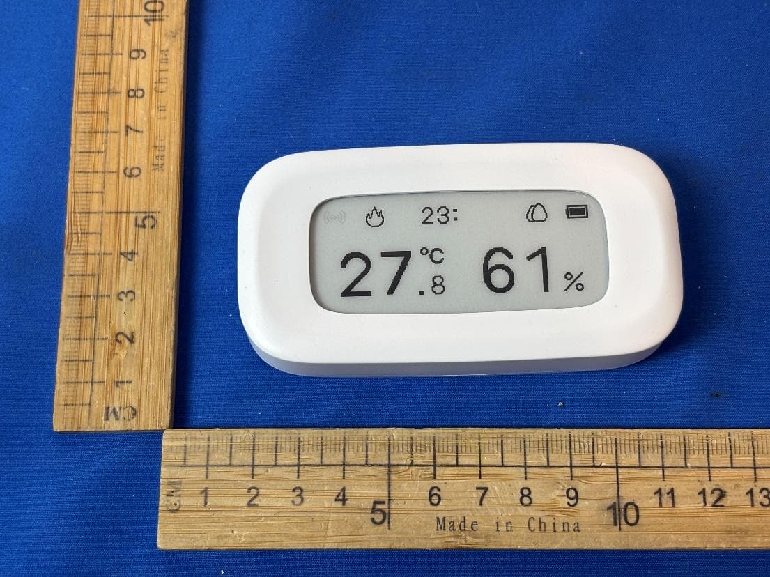
2APN5-SNZB02UL
Aug 12, 2026Zigbee Temperature Humidity Sensor
Equipment Class
DTS - Digital Transmission System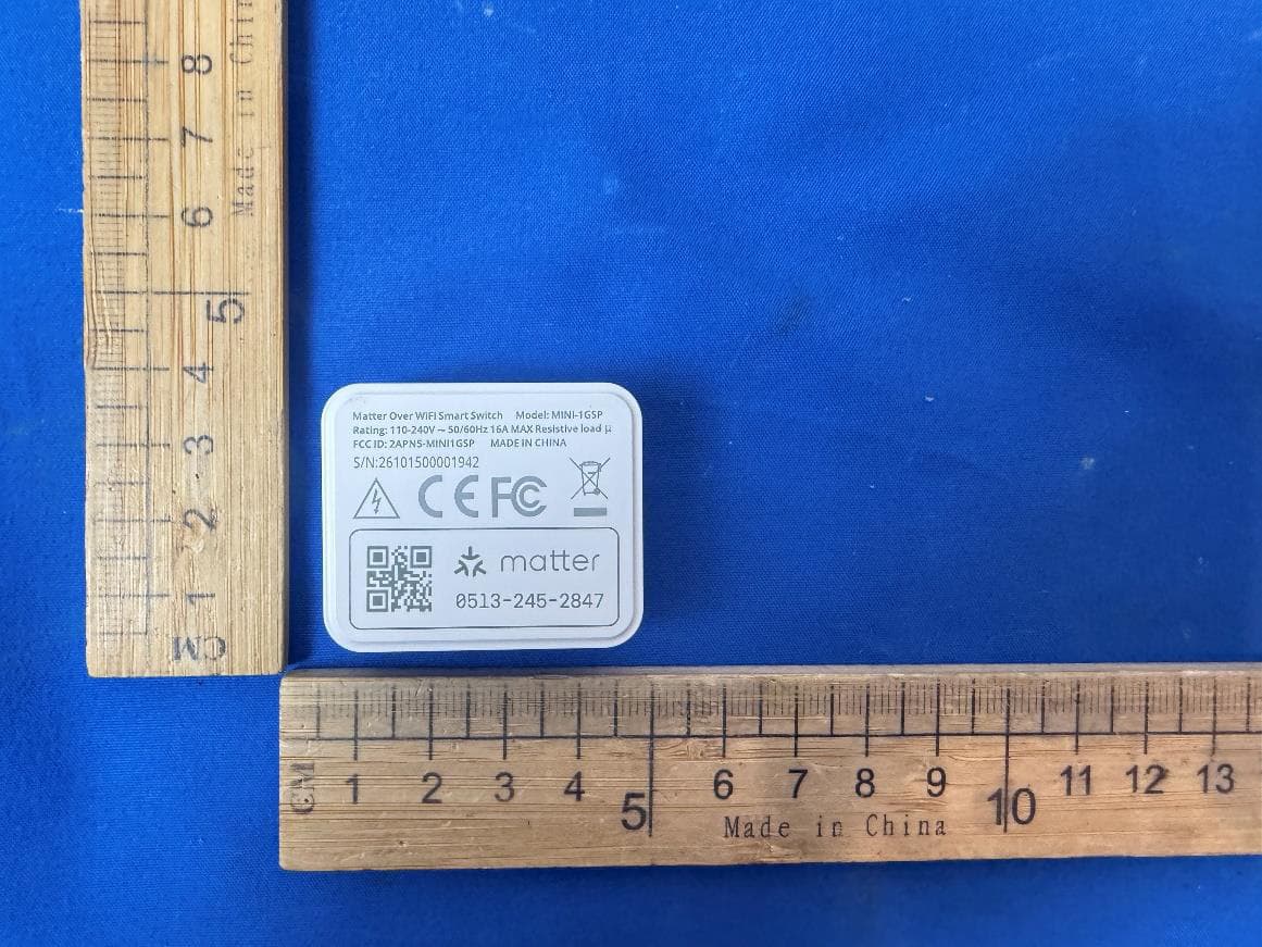
2APN5-MINI1GSP
Jul 15, 2026Matter Over WiFi Smart Switch
Equipment Class
DTS - Digital Transmission System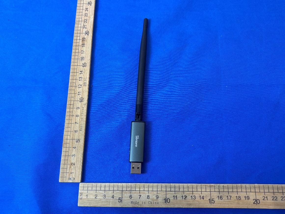
2APN5-DONGLEPP10
Jul 13, 2026Zigbee/Thread USB Dongle
Equipment Class
DTS - Digital Transmission System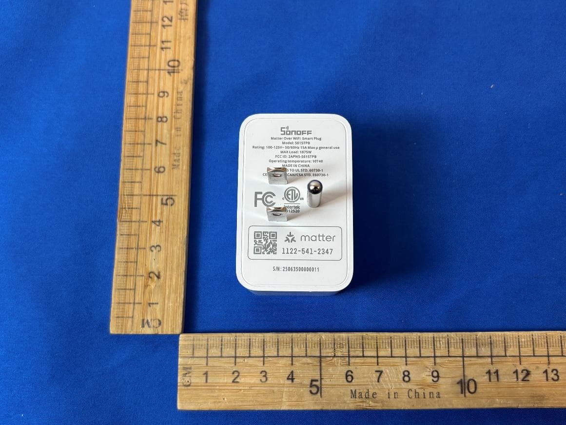
2APN5-S61STPB
Jul 10, 2026Matter Over WiFi Smart Plug
Equipment Class
DTS - Digital Transmission System
2APN5-SNZB09P
Jul 08, 2026Zigbee Siren
Equipment Class
DTS - Digital Transmission System