2APQ9-S5CHandheld 3-axis Gimbal Stabilizer
Shenzhen JX ROBOT Technology Co., Ltd.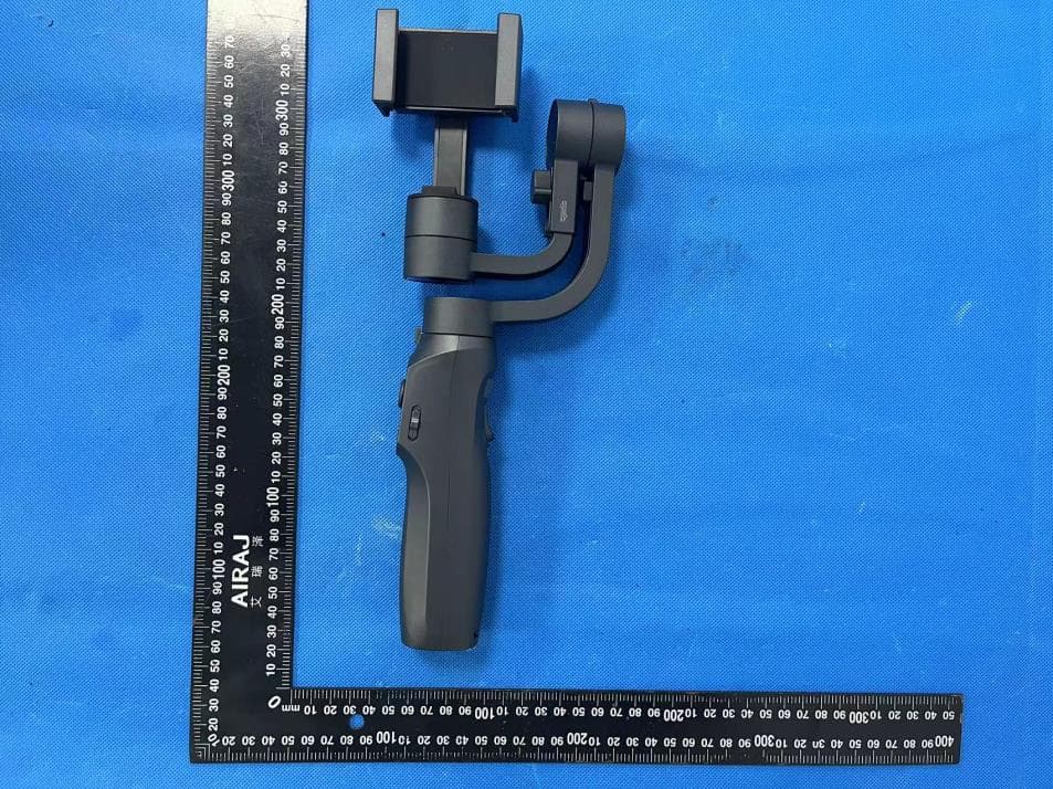
Click to zoom
Application Details
- Equipment Class
- DSS - Part 15 Spread Spectrum Transmitter
- Date of Grant
- Jul 02, 2024
- Application Purpose
- Original Equipment
- Date of Application
- Jul 02, 2024
- Equipment Note
- Handheld 3-axis Gimbal Stabilizer
- Frequency Range
- 2402.00000000 - 2480.00000000
- Country
- China
Documents & Files
Document Text
Text extracted from the exhibit documents filed with the FCC. Open a document above to read the original.
Users Manual
* Smartphone is not included S5C Handheld 3-axis Gimbal Stabilizer Quick start01 P ow er on/o 02 Bluetooth connect by native camera02 I nstructions for f our modes03 Gimbal overview05 Hor izontal & vertical swit ch07 Charging08 About APP09 Speci cation11 C aution12 Storage and maintenance12 CONTENTS Quick start (Don’t power on) 1. Remove the smartphone case before installing, and put the smartphone on the phone holder according to the sticker(as below picture shows), make it is at the middle of holder. 2. Put the smartphone in the phone holder, and let it resists the motor as below picture shows, to avoid the vibration while working. 3. Loosen the balance knob, and adjust the balance arm until the smartphone in nearly balance condition. Balance knob Before power-on, mount your mobile phone according to the arrow sign direction 0102030405060708091011 Power On/O Power on Press the power button until the indicators are on. Bluetooth connect by native camera Power on the gimbal, turn on the bluetooth on the phone, enter smartphone bluetooth setting page, choose the device name “GP5-xxxx” to connect. After connect to the bluetooth, press the shutter button on gimbal to take picture or start & stop video recording. Power o Press the power button until the indicators are o . Power on/o 0102030405060708091011 0102030405060708091011 Instructions for four modes All Follow(AF): The Roll axis is locked, the Pan (left/right) and Tilt(up/down) axes will follow the handle movement. Default mode upon powering on Half Follow(HF): Tilt & Roll axes are locked. Pan axis rotates left/right smoothly with the handle movement. 0102030405060708091011 Lock Full(LF): Pan,Tilt, Roll axis are all locked. The camera remains still and stable, which means the camera cannot follow the movement of the handle First person view(FPV)Pan, Tilt, Roll axis follow the movement of the handle 0102030405060708091011 Phone Go Long press the shutter button until the AF light is ashing, gimbal enters Phone Go mode, release the shutter button, gimbal will exist Phone Go mode. Other Working Mode 0102030405060708091011 Gimbal Overview 1.Mobblie Phone Holder 2.Handle 3.Pitch Motor 4.Adjustable Arm 5.Pan Motor 6.Mode indicator 7.Battery indicator 8.Power Button 9.Joystick 10.Mode switch button 11.Tigger Button 12.Zooming Wheel 13.Micro USB 14.Roll Motor 15.Rope hanging hole 0102030405060708091011 Horizontal & Vertical Switch (Three switching ways) Way 1: 1. Put the gimbal as the below picture shows 2. Press the mode button 3 times, switch from horizontal mode to vertical mode; 3. Press the mode button three times again, switch from vertical back to horizontal mode; Reminder: FPV mode doesn’t support this operation. Way 2: Rotate the smartphone clamp Grasp the holder and rotate the holder directly with 90° 0102030405060708091011 Charging Charge for gimbal Charge for smartphone (when smartphone is put on the clamp horizontally, need use the L-type charging connector) Way 3: Gesture switch 1. Hold the gimbal perpendicular to the ground; 2. Tilt the gimbal left or right with 70°; 3. Gimbal will go to vertical mode automatically; 4. Gimbal will back to horizontal model automatically when hold the gimbal upright; Reminder: FPV mode doesn’t support this operation. About APP This product supports native camera, can do basic stable shooting without APP with native camera. If you want to use more functions (such as zoom, tracking, panoramic and time lapse), need download the app. Gimbal Pro requires iOS 12.0 system and later or Android 8.0 system and later Connect to Gimbal Pro APP 1. Go to setting page on smartphone 2. Go to Bluetooth setting, nd and click the device name “GP5_xxxx” to pair, app will work after connect successfully. Support iOS and Android Download the Gimbal Pro APP Scan the QR code or search “Gimbal pro2” on the Google play store or “Gimbal pro” on App store. 0102030405060708091011 APP interface overview: App 1 2 3 4 76 5 89 15 12 10 14 13 11 1. Video/Photo mode 2. Shooting function select 3. Shoot button 4. Front/Rear camera switch 5. Album 6. Bluetooth icon 7. Face/object tracking 8. Gimbal condition display 9. Gimbal power display 10. Phone power display 11. Flash 12. Home page 13. Camera parameters 14. Gimbal mode adjust 15. Settings 0102030405060708091011 Speci cation 0102030405060708091011 Gimbal Dimension 112 *70 *289mm Tilt Angle330° Roll Angle160° Pan Angle360° Net Weight473g Payload280g Working temperature 0~40 Controllable Tilt Angle+75°/-245° Controllable Roll Angle+80°/-80° Controllable Pan Angle Working Voltage3.4~4.2V(Standard 3.7V) Input Voltage5V Working Time 500mins Input Currency1A Charging Time 210mins Working Currency 150~3000mA (Standard 1500mA) Compatible smartphone range width: 55-90mm diagonal: no more than 192mm/7.72inch; thickness: 7-12mm 1560mins Standby Time: +360°/-360° Caution 1. Ensure the motor rotation is not blocked by external force during and after the stabilizer is powered on; 2. Please do not contact with sea water or corrosive liquid; 3. Please do not disassemble the stabilizer (except for the detachable accessories in the manual); 4. If the motor works continuously for a long time, the surface temperature of the motor may be too high. 5. It is strictly forbidden to drop or collide with the stabilizer, which may damage it and cause abnormal operation; Storage and maintenance 1. Please keep this product away from children and pets; 2. It is forbidden to put the product near the heat source(furnace or heater, etc.) and in the car at hot weather; 3. Please store the product in a dry environment; 4. Do not overcharge or discharge the battery, otherwise the battery cell will be damaged; 5. Do not use the product in the environment with too high or too low temperature; 12 FCC Warning Statement Changes or modifications not expressly approved by the party responsible for compliance could void the userʼs authority to operate the equipment. This equipment has been tested and found to comply wit…
Text truncated - open the document above for the full version.
Attestation Statements
U.S. Agent Designation for Service of Process (Applicant and U.S. Agent are Separate Parties) TO: Federal Communications Commission 7435 Oakland Mills Road Columbia, MD 21046 ATTENTION: FCC Certification – Section 2.911(d)(7) Information Designated U.S. Agent Company Name: HOPEK CORPORATION INC Address: 4358 S BANNOCK ST ENGLEWOOD, CO 80110 United States FRN:0034562900 Contact Name: Peter Davis Tel.: 561-235-6113 Email: [email protected] This letter is to confirm that we (“the Designated U.S. Agent) have accepted the responsibility to act as the Designated U.S. Agent for Service of Process as required by section 47 CFR 2.911(d)(7) on behalf of the Applicant noted below. U.S. Agent Signature: Date: July 2, 2024 Signed by (Printed Name): Peter Davis The Applicant acknowledges that they must maintain an agent for no less than one year after terminating all marketing and importation OR the conclusion of any Commission-related proceeding involving the equipment. The applicant further acknowledges their responsibility to inform the FCC whenever the Designated U.S. Agent information above changes. Applicant Company name: Shenzhen JX ROBOT Technology Co., Ltd Address: 903, Building 1, 7th Industrial Zone, Yulv Community,Yutang Street, Guangming District, Shenzhen, Guangdong, China Contact Name: Alice Chen FRN: 0027506021 FCC ID: 2APQ9-S5C Telephone No: 18664339433 Email: [email protected] Applicant Signature: Date: July 2, 2024 Signed by (Printed Name): Alice Chen
Attestation Statements
(Shenzhen JX ROBOT Technology Co., Ltd) (2024.6.25) Eurofins Electrical and Electronic Testing NA, Inc. 914 West Patapsco Avenue Baltimore, MD 21230 RE: Attestation Statements Part 2.911(d)(5)(i) request for (FCC ID: 2APQ9-S5C) [Shenzhen JX ROBOT Technology Co., Ltd] (“the applicant”) certifies that the equipment for which authorization is sought is not “covered” equipment prohibited from receiving an equipment authorization pursuant to section 2.903 of the FCC rules. Sincerely, (Applicant signature) (Applicant printed name) Alice Chen (Shenzhen JX ROBOT Technology Co., Ltd) (2024.6.25) Eurofins Electrical and Electronic Testing NA, Inc. 914 West Patapsco Avenue Baltimore, MD 21230 RE: Attestation Statements Part 2.911(d)(5)(ii) request for (FCC ID: 2APQ9-S5C) [Shenzhen JX ROBOT Technology Co., Ltd] (“the applicant”) certifies that, as of the date of the filing of the application, the applicant is not identified on the Covered List as an entity producing “covered” equipment. Sincerely, (Applicant signature) (Applicant printed name) Alice Chen
Cover Letter(s)
Shenzhen JX ROBOT Technology Co., Ltd 2024.6.25 Eurofins Electrical and Electronic Testing NA, Inc. 914 W. Patapsco Avenue Baltimore, MD 21230 USA RE: LETTER OF AGENT AUTHORIZATION To Whom It May Concern: We, the undersigned, hereby authorize Shenzhen BCTC Testing Co., Ltd to act on our behalf in all matters relating to application for equipment authorization, including the signing of all documents relating to these matters. We also hereby certify that no party to the application authorized hereunder is subject to the denial of benefits, including FCC benefits, pursuant to Section 5301 of the Anti-Drug Abuse Act of 1988, 21 U.S.C.853(a). This agreement expires one year from the current date. Sincerely, Client’s signature: Client’s name / title : Alice Chen / Manager Contact information / address: 903, Building 1, 7th Industrial Zone, Yulv Community,Yutang Street, Guangming District, Shenzhen, Guangdong, China
Cover Letter(s)
Shenzhen JX ROBOT Technology Co., Ltd 2024.6.25 Eurofins Electrical and Electronic Testing NA, Inc. 914 W. Patapsco Avenue Baltimore, MD 21230 USA RE: CONFIDENTIALITY REQUEST FOR EUT NAME: Handheld 3-axis Gimbal Stabilizer Trademark: N/A MODEL: S5C S5Cpro, S5, S5pro, S5B, S5Bpro FCC ID: 2APQ9-S5C To Whom It May Concern: This letter serves as an official request for confidentiality under sections 0.457 and 0.459 of CFR 47. We have requested that the - Block Diagram - Schematics - Operational Description required to be submitted with this application be permanently withheld from public review. The above materials contain trade secrets and proprietary information not customarily released to the public. The public disclosure of these materials may be harmful to the applicant and provide unjustified benefits to its competitors. Please contact me if there is any information you may need. Sincerely, Client’s signature: Client’s name / title : Alice Chen / Manager Contact information / address: 903, Building 1, 7th Industrial Zone, Yulv Community,Yutang Street, Guangming District, Shenzhen, Guangdong, China
Cover Letter(s)
Shenzhen JX ROBOT Technology Co., Ltd Model Difference 2024/6/25 EUT NAME: Handheld 3-axis Gimbal Stabilizer Trademark: N/A MODEL: S5C S5Cpro, S5, S5pro, S5B, S5Bpro FCC ID: 2APQ9-S5C All the models are the same circuit and RF module, except model names and appearance of the color. Regards Sincerely Client’s signature: Client’s name / title : Alice Chen / Manager Contact information / address: 903, Building 1, 7th Industrial Zone, Yulv Community,Yutang Street, Guangming District, Shenzhen, Guangdong, China
External Photos
External Photos
ID Label/Location Info
Label & label location Label: FCC ID: 2APQ9-S5C
Internal Photos
Internal Photos Antenna
RF Exposure Info
RF EXPOSURE EVALUATION METHOD FCC ID: 2APQ9-S5C Applicable standard: In accordance with FCC 47 CFR part 2 (2.1093) this device has been defined as a portable device which is defined as a transmitting device designed to be used so that the radiating structure(s) of the device is/are within 20 centimeters of the body of the user. Portable devices must be evaluated using the specified in FCC 47 CFR part 2 (2.1093) and ANSI/IEEEC95.1-1992. and had been tested in accordance with the measurement methods and procedures specified in IEEE 1528-2003. Per FCC KDB 447498 D01 v06, the 1-g and 10-g SAR test exclusion thresholds for 100 MHz to 6 GHz at test separation distances s 50 mm are determined by: SAR Test Exclusion Thresholds for 100 MHz – 6 GHz and ≤ 50 mm Approximate SAR Test Exclusion Power Thresholds at Selected Frequencies and Test Separation Distances are illustrated in the following Table. The 1-g and 10-g SAR test exclusion thresholds for 100 MHz to 6 GHz at test separation distances ≤ 50 mm are determined by: [(max. power of channel, including tune-up tolerance, mW)/(min. test separation distance, mm)] · [√f(GHz)] ≤ 3.0 for 1-g SAR and ≤ 7.5 for 10-g extremity SAR,where f(GHz) is the RF channel transmit frequency in GHz Power and distance are rounded to the nearest mW and mm before calculation The result is rounded to one decimal place for comparison The test exclusions are applicable only when the minimum test separation distance is ≤ 50 mm and for transmission frequencies between 100 MHz and 6 GHz. When the minimum test separation distance is < 5 mm, a distance of 5 mm is applied to determine SAR test exclusion. BT Frequency Maximum Conducted Output Power(PK) Conducted Output Power Limit (MHz) (dBm) dBm GFSK 2402 -2.04 21 2441 -1.76 21 2480 -2.22 21 π/ 4 DQPSK 2402 -1.25 21 2441 -1.04 21 2480 -1.52 21 8DPSK 2402 -0.81 21 2441 -0.62 21 2480 -1.05 21 max possible output power (PK,conducted):0±1dBm 1dBm=1.26mW 2402MHz [(max. power of channel, including tune-up tolerance, mW)/(min. test separation distance,mm)] · [√f(GHz)]= 1.26/5*√2.402=0.391≤3.0 2441MHz [(max. power of channel, including tune-up tolerance, mW)/(min. test separation distance,mm)] · [√f(GHz)]= 1.26/5*√2.441=0.394≤3.0 2480MHz [(max. power of channel, including tune-up tolerance, mW)/(min. test separation distance,mm)] · [√f(GHz)]= 1.26/5*√2.48=0.397≤3.0 Conclusion: 1. [(max. power of channel, including tune-up tolerance, mW)/(min. test separation distance, mm)] * [√f(GHz)] < 3.0. 2. SAR Test Exclusion Thresholds is 3.0 for separation distance 5mm. Therefore, SAR test is not required.
Test Report
OA-C07规格书 广州寒武纪电子科技有限公司 OA-C07_V01 1 SMD Antenna Spec. OverAir ® SMD 天线系列 符合RoHS规范 PN: OA-C07 2.4 GHz ISM antenna OA-C07规格书 广州寒武纪电子科技有限公司 OA-C07_V01 2 特点 1.尺寸仅3.5 X 1.7 X 1.2 mm 3 的小尺寸SMD贴片天线. 2.低能量损耗,高天线效率。 3.在温湿度变化的情况下具有高稳定性。 应用 1.2.4GHz ISM 频段天线应用 2.蓝牙、ZigBee、无线应用、智能家居应用等 3.WIFI(仅2.4G) 结构 不区分天线两端的馈电焊盘和固定焊盘 尺寸Size 三视图 符号 尺寸(mm) L 3.5±0.2 w 1.7±0.1 T 1.2±0.1 a 0.4±0.1 Manufacturer: Guangzhou Hanwuji Electronic Technology Co.,Ltd OA-C07规格书 广州寒武纪电子科技有限公司 OA-C07_V01 3 电气特性 OA-C07 Specification 工作频率范围Working Frequency 2450±50MHz 带宽Band Width >100MHz 阻抗Impedance 50Ω 增益Gain(dBi) 3.74(peak) 驻波比VSWR <2 工作温度Operation Temperature -40°C~+95°C 可承受功率Power Capacity 3W 天线2.4G工作频率需要通过阻抗匹配器件调试来实现. 天线焊盘和走线设计 PCB原理图 PCB设计尺寸图 OA-C07规格书 广州寒武纪电子科技有限公司 OA-C07_V01 4 匹配器件值 串联器件Series 1 高频电感 5.6nh 并联器件Shunt 1高频电感 4.7nh 串联器件Series 2 电阻0Ω OA-C07规格书 广州寒武纪电子科技有限公司 OA-C07_V01 5 测试板上天线测试 (板厚 1.0mm)Test plate antenna test (plate thickness 1.0mm) Antenna S11 characteristics Antenna VSWR characteristics OA-C07规格书 广州寒武纪电子科技有限公司 OA-C07_V01 6 效率和辐射图 Efficiency and radiation maps 效率、辐射图、增益等性能是基于测试板设计得到的。 OA- C07 天线的规格特性测试数据是 基于测试 PCB 板尺寸以及下图所示的测试方向所得到的。以下数据是在 ET S 3D 微波暗室测 试完成的. 增益和效率 带宽 2.4G-2.5GHz 峰值增益Peak Gain 3.74dBi 带内平均增益 Average Gain across the band 3.66dBi 带内增益范围 Gain Range across the band 3.42dBi~3.74dBi 峰值效率Peak Efficiency 58.9% 带内平均效率 Average Efficiency across the band 55.9% Z Y X OA-C07规格书 广州寒武纪电子科技有限公司 OA-C07_V01 7 带内效率范围 Efficiency Range across the band 53.0%~58.9% Theta @2.45 GHz Phi @2.45 GHz Total @2.45 GHz 焊接条件 可靠无损的典型焊接规范如下图所示: OA-C07规格书 广州寒武纪电子科技有限公司 OA-C07_V01 8 包装 塑胶载带规格 (单位:mm) OA-C07规格书 广州寒武纪电子科技有限公司 OA-C07_V01 9 Index Ao Bo ΦD T W Dimension (mm) 2.0±0.1 4.0±0.1 1.55±0.05 1.8±0.1 12±0.1 Index E F Po P1 P2 Dimension (mm) 1.5±0.1 5.4±0.1 4.0±0.1 4.0±0.1 2.0±0.1 卷盘尺寸 Index A B C Dimension(mm) 330 100 13.5 标准数量: 3000 PCS/盘. 存储环境 产品存储时应满足下列条件: 温度 : -10°C~+40°C 湿度 : 30% 至 70% 相对湿度 产品放置的位置不要接触腐蚀性气体,如硫磺等。氯气或酸可能导致产品电极氧化 造成可焊接性变差。 产品应放置在工具箱里且避免受潮、灰尘的影响。 产品应存放在仓库中且避免热、振动、阳光直射。 产品应在密闭条件下储存。
Test Report
No.:BCTC/RF-EMC-005 Page: 1 of 85 Edition:B.2 TEST REPORT Shenzhen BCTC Testing Co., Ltd. Report No.: BCTC2406219375E Applicant: Shenzhen JX ROBOT Technology Co., Ltd Product Name: Handheld 3-axis Gimbal Stabilizer Test Model: S5C Tested Date: 2024-06-03 to 2024-06-18 Issued Date: 2024-06-19 Report No.: BCTC2406219375E No.:BCTC/RF-EMC-005 Page: 2 of 85 Edition:B.2 FCC ID: 2APQ9-S5C The test report is effective only with both signature and specialized stamp.This result(s) shown in this report refer only to the sample(s) tested. Without written approval of Shenzhen BCTC Testing Co., Ltd, this report can’t be reproduced except in full.The tested sample(s) and the sample information are provided by the client. Product Name: Handheld 3-axis Gimbal Stabilizer Trademark: N/A Model/Type Reference: S5C S5Cpro, S5, S5pro, S5B, S5Bpro Prepared For: Shenzhen JX ROBOT Technology Co., Ltd Address: 903, Building 1, 7th Industrial Zone, Yulv Community,Yutang Street, Guangming District, Shenzhen, Guangdong, China Manufacturer: Shenzhen JX ROBOT Technology Co., Ltd Address: 903, Building 1, 7th Industrial Zone, Yulv Community,Yutang Street, Guangming District, Shenzhen, Guangdong, China Prepared By: Shenzhen BCTC Testing Co., Ltd. Address: 1-2/F., Building B, Pengzhou Industrial Park, No.158, Fuyuan 1st Road, Zhancheng, Fuhai Subdistrict, Bao'an District, Shenzhen, Guangdong, China Sample Received Date: 2024-06-03 Sample Tested Date: 2024-06-03 to 2024-06-18 Issue Date: 2024-06-19 Report No.: BCTC2406219375E Test Standards: FCC Part15.247 ANSI C63.10-2013 Test Results: PASS Remark: This is Bluetooth Classic radio test report. Tested by: Approved by: Shanshan. Zhang / Project Handler Zero Zhou/Reviewer Report No.: BCTC2406219375E No.:BCTC/RF-EMC-005 Page: 3 of 85 Edition:B.2 Table Of Content Test Report Declaration Page 1. Version .................................................................................................................. 5 2. Test Summary ....................................................................................................... 6 3. Measurement Uncertainty ..................................................................................... 7 4. Product Information And Test Setup ..................................................................... 8 4.1 Product Information ............................................................................................... 8 4.2 Test Setup Configuration ...................................................................................... 9 4.3 Support Equipment ............................................................................................... 9 4.4 Channel List ........................................................................................................ 10 4.5 Test Mode ........................................................................................................... 10 4.6 Table Of Parameters Of Text Software Setting ................................................... 10 5. Test Facility And Test Instrument Used ............................................................... 11 5.1 Test Facility ......................................................................................................... 11 5.2 Test Instrument Used .......................................................................................... 11 6. Conducted Emissions .......................................................................................... 13 6.1 Block Diagram Of Test Setup .............................................................................. 13 6.2 Limit .................................................................................................................... 13 6.3 Test procedure .................................................................................................... 13 6.4 EUT operating Conditions ................................................................................... 13 6.5 Test Result .......................................................................................................... 14 7. Radiated emissions ............................................................................................. 16 7.1 Block Diagram Of Test Setup .............................................................................. 16 7.2 Limit .................................................................................................................... 17 7.3 Test procedure .................................................................................................... 18 7.4 EUT operating Conditions ................................................................................... 19 7.5 Test Result .......................................................................................................... 19 8. Radiated Band Emission Measurement And Restricted Bands Of Operation ..... 25 8.1 Block Diagram Of Test Setup .............................................................................. 25 8.2 Limit .................................................................................................................... 25 8.3 Test procedure .................................................................................................... 26 8.4 EUT operating Conditions ................................................................................... 26 8.5 Test Result .......................................................................................................... 27 9. Spurious RF Conducted Emissions ..................................................................... 28 9.1 Block Diagram Of Test Setup .............................................................................. 28 9.2 Limit .................................................................................................................... 28 9.3 Test procedure .................................................................................................... 28 9.4 …
Text truncated - open the document above for the full version.
Test Report
Report No.: BCTC2406219375E No.:BCTC/RF-EMC-005 Page: 45 of 85 Edition:B.2 Band Edge(Hopping) NVNT 1-DH1 2480MHz Hopping Ref Band Edge(Hopping) NVNT 1-DH1 2480MHz Hopping Emission Report No.: BCTC2406219375E No.:BCTC/RF-EMC-005 Page: 46 of 85 Edition:B.2 Band Edge(Hopping) NVNT 2-DH1 2402MHz Hopping Ref Band Edge(Hopping) NVNT 2-DH1 2402MHz Hopping Emission Report No.: BCTC2406219375E No.:BCTC/RF-EMC-005 Page: 47 of 85 Edition:B.2 Band Edge(Hopping) NVNT 2-DH1 2480MHz Hopping Ref Band Edge(Hopping) NVNT 2-DH1 2480MHz Hopping Emission Report No.: BCTC2406219375E No.:BCTC/RF-EMC-005 Page: 48 of 85 Edition:B.2 Band Edge(Hopping) NVNT 3-DH1 2402MHz Hopping Ref Band Edge(Hopping) NVNT 3-DH1 2402MHz Hopping Emission Report No.: BCTC2406219375E No.:BCTC/RF-EMC-005 Page: 49 of 85 Edition:B.2 Band Edge(Hopping) NVNT 3-DH1 2480MHz Hopping Ref Band Edge(Hopping) NVNT 3-DH1 2480MHz Hopping Emission Report No.: BCTC2406219375E No.:BCTC/RF-EMC-005 Page: 50 of 85 Edition:B.2 10. 20 dB Bandwidth 10.1 Block Diagram Of Test Setup 10.2 Limit N/A 10.3 Test procedure 1. Set RBW = 30kHz. 2. Set the video bandwidth (VBW) ≥ 3 x RBW. 3. Detector = Peak. 4. Trace mode = max hold. 5. Sweep = auto couple. 6. Allow the trace to stabilize. 7. Measure the maximum width of the emission that is constrained by the frequencies associated with the two outermost amplitude points (upper and lower frequencies) that are attenuated by 6 dB relative to the maximum level measured in the fundamental emission. 10.4 Test Result Condition Mode Frequency (MHz) -20 dB Bandwidth (MHz) Verdict NVNT 1-DH1 2402 0.833 Pass NVNT 1-DH1 2441 0.874 Pass NVNT 1-DH1 2480 0.863 Pass NVNT 2-DH1 2402 1.242 Pass NVNT 2-DH1 2441 1.276 Pass NVNT 2-DH1 2480 1.288 Pass NVNT 3-DH1 2402 1.201 Pass NVNT 3-DH1 2441 1.244 Pass NVNT 3-DH1 2480 1.223 Pass Report No.: BCTC2406219375E No.:BCTC/RF-EMC-005 Page: 51 of 85 Edition:B.2 Test Graphs -20dB Bandwidth NVNT 1-DH1 2402MHz -20dB Bandwidth NVNT 1-DH1 2441MHz Report No.: BCTC2406219375E No.:BCTC/RF-EMC-005 Page: 52 of 85 Edition:B.2 -20dB Bandwidth NVNT 1-DH1 2480MHz -20dB Bandwidth NVNT 2-DH1 2402MHz Report No.: BCTC2406219375E No.:BCTC/RF-EMC-005 Page: 53 of 85 Edition:B.2 -20dB Bandwidth NVNT 2-DH1 2441MHz -20dB Bandwidth NVNT 2-DH1 2480MHz Report No.: BCTC2406219375E No.:BCTC/RF-EMC-005 Page: 54 of 85 Edition:B.2 -20dB Bandwidth NVNT 3-DH1 2402MHz -20dB Bandwidth NVNT 3-DH1 2441MHz Report No.: BCTC2406219375E No.:BCTC/RF-EMC-005 Page: 55 of 85 Edition:B.2 -20dB Bandwidth NVNT 3-DH1 2480MHz Report No.: BCTC2406219375E No.:BCTC/RF-EMC-005 Page: 56 of 85 Edition:B.2 11. Maximum Peak Output Power 11.1 Block Diagram Of Test Setup 11.2 Limit FCC Part15 (15.247) , Subpart C Section Test Item Limit Frequency Range (MHz) Result 15.247(b)(1) Peak Output Power 0.125 watt or 21dBm 2400-2483.5 PASS 11.3 Test procedure 1. Remove the antenna from the EUT and then connect a low RF cable from the antenna port to the spectrum. 2. Set the spectrum analyzer: RBW = 2MHz. VBW = 6MHz. Sweep = auto; Detector Function = Peak. 3. Keep the EUT in transmitting at lowest, medium and highest channel individually. Record the max value. 11.4 Test Result Condition Mode Frequency (MHz) Conducted Power (dBm) Limit (dBm) Verdict NVNT 1-DH1 2402 -2.04 21 Pass NVNT 1-DH1 2441 -1.76 21 Pass NVNT 1-DH1 2480 -2.22 21 Pass NVNT 2-DH1 2402 -1.25 21 Pass NVNT 2-DH1 2441 -1.04 21 Pass NVNT 2-DH1 2480 -1.52 21 Pass NVNT 3-DH1 2402 -0.81 21 Pass NVNT 3-DH1 2441 -0.62 21 Pass NVNT 3-DH1 2480 -1.05 21 Pass Report No.: BCTC2406219375E No.:BCTC/RF-EMC-005 Page: 57 of 85 Edition:B.2 Test Graphs Power NVNT 1-DH1 2402MHz Power NVNT 1-DH1 2441MHz Report No.: BCTC2406219375E No.:BCTC/RF-EMC-005 Page: 58 of 85 Edition:B.2 Power NVNT 1-DH1 2480MHz Power NVNT 2-DH1 2402MHz Report No.: BCTC2406219375E No.:BCTC/RF-EMC-005 Page: 59 of 85 Edition:B.2 Power NVNT 2-DH1 2441MHz Power NVNT 2-DH1 2480MHz Report No.: BCTC2406219375E No.:BCTC/RF-EMC-005 Page: 60 of 85 Edition:B.2 Power NVNT 3-DH1 2402MHz Power NVNT 3-DH1 2441MHz Report No.: BCTC2406219375E No.:BCTC/RF-EMC-005 Page: 61 of 85 Edition:B.2 Power NVNT 3-DH1 2480MHz Report No.: BCTC2406219375E No.:BCTC/RF-EMC-005 Page: 62 of 85 Edition:B.2 12. Hopping Channel Separation 12.1 Block Diagram Of Test Setup 12.2 Limit Frequency hopping systems shall have hopping channel carrier frequencies separated by a minimum of 25 kHz or the 20 dB bandwidth of the hopping channel, whichever is greater. Alternatively, frequency hopping systems operating in the 2400-2483.5 MHz band may have hopping channel carrier frequencies that are separated by 25 kHz or two-thirds of the 20 dB bandwidth of the hopping channel, whichever is greater, provided the systems operate with an output power no greater than 0.125W. 12.3 Test procedure 1. Remove the antenna from the EUT and then connect a low RF cable from the antenna port to the spectrum. 2. Set the spectrum analyzer: RBW = 30kHz. VBW = 100kHz , Span = 2.0MHz. Sweep = auto; Detector Function = Peak. Trace = Max hold. 3. Allow the trace to stabilize. Use the marker-delta function to determine the separation between the peaks of the adjacent channels. The limit is specified in one of the subparagraphs of this Section Submit this plot. 12.4 Test Result odulation Test Channel Separation (MHz) Limit(MHz) Result GFSK Low 1.002 0.555 PASS GFSK Middle 1.000 0.583 PASS GFSK High 1.000 0.575 PASS π/4 DQPSK Low 1.000 0.828 PASS π/4 DQPSK Middle 1.000 0.851 PASS π/4 DQPSK High 1.000 0.859 PASS 8DPSK Low 1.002 0.801 PASS 8DPSK Middle 1.000 0.829 PASS 8DPSK High 0.998 0.815 PASS Report No.: BCTC2406219375E No.:BCTC/RF-EMC-005 Page: 63 of 85 Edition:B.2 Test Graphs CFS NVNT 1-DH1 2402MHz CFS NVNT 1-DH1 2441MHz Report No.: BCTC2406219375E No.:BCTC/RF-EMC-005 Page: 64 of 85 Edition:B.2 CFS NVNT 1-DH1 2480MHz CFS NVNT 2-DH1 2402MHz Report No.: BCTC2406219375E No.:BCTC/RF-EMC-005 Page: 65 of 85 Edition:B.2 CFS NVNT 2-DH1 2441MHz CFS NVNT 2-DH1 2480MHz Report No.: BCTC2406219375E No.:BCTC/RF-EMC-005 Page: 66 of…
Text truncated - open the document above for the full version.
Test Setup Photos
Conducted emissions Radiated Measurement Photos
Contact Information
Applicant
Alice Chen(Manager)
Test Firm
Shenzhen BCTC Testing Co., Ltd.Sally He
[email protected]15999690624
Technical Specifications
| # | Rule Parts | Frequency Range | Power Output |
|---|---|---|---|
| 1 | 15C | 2.40 GHz - 2.48 GHz | 870.00 µW |
Other Applications from Shenzhen JX ROBOT Technology Co., Ltd.
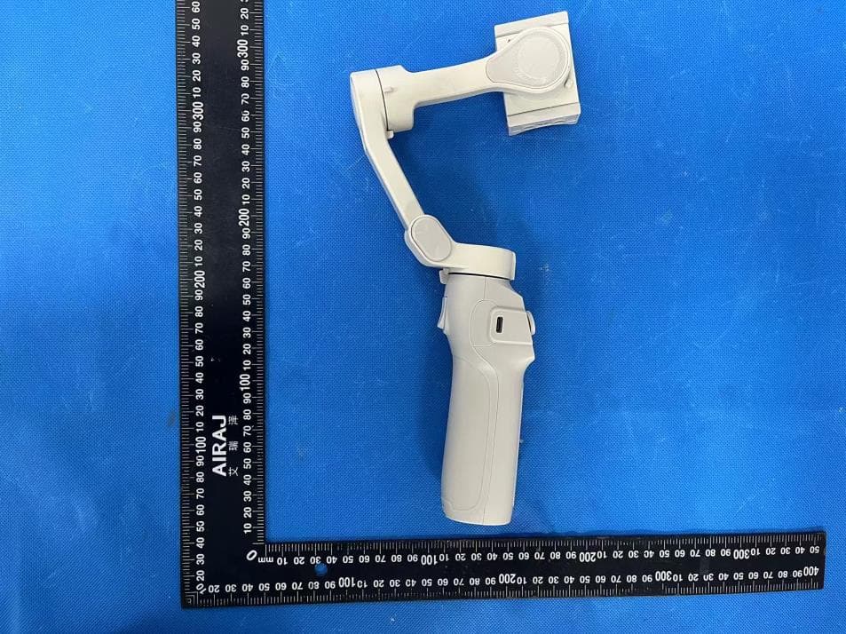
2APQ9-L9-LITE
Jul 02, 20243 axis foldable gimbal
Equipment Class
DSS - Part 15 Spread Spectrum Transmitter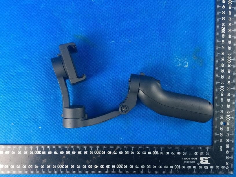
2APQ9-L7-1
Jan 11, 2021Foldable 3 axis gimbal stabilizer
Equipment Class
DSS - Part 15 Spread Spectrum Transmitter