2APU5BWPC100Wireless Charger
JMTek Industries( Shenzhen) Co.,Ltd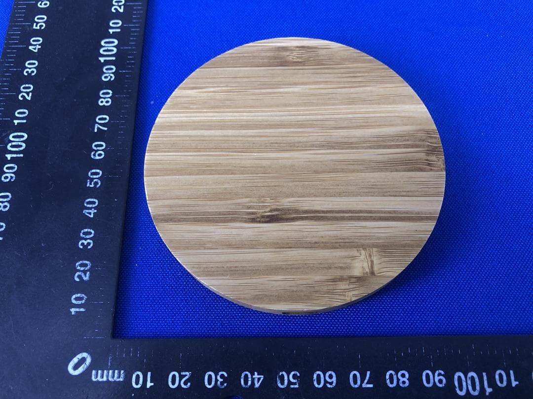
Click to zoom
Application Details
- Equipment Class
- DCD - Part 15 Low Power Transmitter Below 1705 kHz
- Date of Grant
- Aug 25, 2021
- Application Purpose
- Original Equipment
- Date of Application
- Aug 25, 2021
- Equipment Note
- Wireless Charger
- Frequency Range
- 0.11000000 - 0.20500000
- Country
- China
Documents & Files
Document Text
Text extracted from the exhibit documents filed with the FCC. Open a document above to read the original.
Users Manual
Wireless Charger Instruction Manual Congratulations on your purchase of this Wireless Charger. To ensure a long service life and optimal functionality of this product we recommend that you read this manual carefully. Package Content 1 Wireless Charger 1 USB Charging Cable 1 User Manual Specifications Input: 5V⎓2A,9V⎓2A,12V⎓1.5A Wireless Output: 5W, 7.5W, 10W, 15W Charging distance≤6mm Instructions 1. Connect the wireless charger with the included USB charging cable to the wall charger and plug the charger into an electronic socket. while the red led will light up. 2. Place the smartphone with the display facing up on the center of the wireless charger or adjust the placement position until the charging process starts. Then the blue led lightsup. 3. When the smartphone is fully charged, remove it from the wirelesscharger. . When the charging is completed, your smartphone will indicate that the battery is full. (check the smartphone’s battery status using the charging icon displayed on the screen) 4. Tosave energy, unplug the charger when not in use. General usage tips . Do not place any metal objects between the smartphone and the wireless charger . To ensure more effective charging, remove protective cases. . Charging time depends on battery capacity, phone input specifications, current phone energy consumption, phone position on the wireless charger, charging distance, etc. Possible causes of wireless charging problems . Your device is not compatible with the Qi wireless charging standard. . Your device is placed on the wireless charger in a wrong way. See the manual of your smartphone to find the exact place of the built-in Qi wireless charging receiver. . A protective case of the smartphone or another object on the back of the smartphone is blocking the charging process. . The USB charger is too weak, defective or unplugged from the electric socket. . The charging cable is unplugged, broken or too weak for correct functioning. Safety information BWPC100 . Do not drop or cause an impact on the device. . Do not disassemble, modify or repair your device. . Keep away from humidity and heat. . Keep it beyond the reach of children. FCC Statement Changes or modifications not expressly approved by the party responsible for compliance could void the user's authority to operate the equipment. This equipment has been tested and found to comply with the limits for a Class B digital device, pursuant to Part 15 of the FCC Rules. These limits are designed to provide reasonable protection against harmful interference in a residential installation. This equipment generates uses and can radiate radio frequency energy and, if not installed and used in accordance with the instructions, may cause harmful interference to radio communications. However, there is no guarantee that interference will not occur in a particular installation. If this equipment does cause harmful interference to radio or television reception, which can be determined by turning the equipment off and on, the user is encouraged to try to correct the interference by one or more of the following measures: -- Reorient or relocate the receiving antenna. -- Increase the separation between the equipment and receiver. -- Connect the equipment into an outlet on a circuit different from that to which the receiver is connected. -- Consult the dealer or an experienced radio/TV technician for help This device complies with part 15 of the FCC rules. Operation is subject to the following two conditions (1)this device may not cause harmful interference, and (2) this device must accept any interference received, including interference that may cause undesired operation. This equipment complies with FCC radiation exposure limits set forth for an uncontrolled environment. This equipment should be installed and operated with minimum distance 20cm between the radiator & your body.
Cover Letter(s)
JMTek Industries(Shenzhen) Co., Ltd. Office of Engineering Technology Federal Communications Commission 7435 Oakland Mills Road Columbia, MD 21046 USA Date: 2021-07-28 Subject; Request for Long Term Confidentiality FCC ID: 2APU5BWPC100 To Whom It May Concern, Pursuant to the provisions of the Commission’s rules Title 47 Sections §0.457 and §0.459, we are requesting the Commission to withhold the following attachment(s) as confidential documents from public disclosure indefinitely. These documents contain detailed system and equipment descriptions and are considered as proprietary information in operation of the equipment. The public disclosure of these documents might be harmful to our company and would give competitors an unfair advantage in the market. Schematic Diagram Block Diagram Parts List Operational Description Tune-up Procedure It is our understanding that all measurement test reports, FCC ID label format and correspondence during the certification review process cannot be granted as confidential documents and this information will be available for public review once the grant of equipment authorization is issued. Sincerely, Signature: Name: Cici Jiang Title: GM
Cover Letter(s)
JMTek Industries(Shenzhen) Co., Ltd. 14G, Innovation Tech Building, Quanzhi Science and Technology innovation Park, ShaJing Street, Baoan District, ShenZhen 518104, China Agent Authorization Company: JMTek Industries(Shenzhen) Co., Ltd. Address: 14G, Innovation Tech Building, Quanzhi Science and Technology innovation Park, ShaJing Street, Baoan District, ShenZhen,518104, China Product Name: Wireless Charger Model Number(s): BWPC100, BWPC200 Product Description: Wireless Charger We authorize MiCOM Labs Inc., 575 Boulder Court, Pleasanton, California 94566, USA, to act on our behalf on all matters concerning the certification of above named equipment. We declare that MiCOM Labs Inc. is allowed to forward all information related to the approval and certification of equipment to the regulatory agencies as required and to discuss any issues concerning the approval application. Any and all acts carried out by MiCOM Labs on our behalf shall have the same effect as acts of our own. Signature: Date: 2021-07-28 Name: Cici Jiang Title: GM Company: JMTek Industries(Shenzhen) Co., Ltd.
External Photos
Page 1 of 4 Appendix B: Photographs of EUT Product: Wireless Charger Model: BWPC100 External Photos Page 2 of 4 Page 3 of 4 Page 4 of 4
ID Label/Location Info
Label Artwork and Location Model: BWPC100 Label: Size: L*W=35*20mm Location
Internal Photos
Page 1 of 3 Appendix B: Photographs of EUT Product: Wireless Charger Model: BWPC100 Internal Photos Page 2 of 3 Page 3 of 3 ANT
RF Exposure Info
RF Exposure Considerations 1. Measuring Standard KDB 680106 D01 RF Exposure Wireless Charging Apps v03 2. Requirements According to the item 5.b of KDB 680106 D01v03: Inductive wireless power transfer applications with supporting field strength results and meeting all of the following requirements are not required to submit a KDB inquiry for devices approved using SDoC or a PAG for equipment approved using certification to address RF exposure compliance. However, the responsible party is required to keep a copy of the test report in accordance with KDB 865664 D02. A copy of the test report is to be submitted with the application if the device is approved using certification. (1) Power transfer frequency is less than 1 MHz. (2) Output power from each primary coil is less than or equal to 15 watts. (3) The transfer system includes only single primary and secondary coils. This includes charging systems that may have multiple primary coils and clients that are able to detect and allow coupling only between individual pairs of coils. (4) Client device is placed directly in contact with the transmitter. (5) Mobile exposure conditions only (portable exposure conditions are not covered by this exclusion). (6) The aggregate H-field strengths at 15 cm surrounding the device and 20 cm above the top surface from all simultaneous transmitting coils are demonstrated to be less than 50% of the MPE limit. Limits For Maximum Permissible Exposure (MPE) 3. Test Setup Note: Measurements should be made from all sides and the top of the primary/client pair, with the 15cm measured from the center of the probe(s) to the edge of the device. 4.Test Procedure 1) The RF exposure test was performed in anechoic chamber. 2) The measurement probe was placed at 15 cm surrounding the device and 20 cm above the top surface of the charger and the geometric center of probe. 3) The highest emission level was recorded and compared with limit as soon as measurement of each points (A, B, C, D, E) were completed. 4) The EUT was measured according to the dictates of KDB 680106 D01 v03. Remark; The EUT’s test position A, B, C, D and E is valid for the E and H field measurements. 5. Test Equipment List Equipment Manufacturer Model No. Calibration Due Magnetic field meter NARDA ELT-400 Mar. 07, 2022 Mobile Phone SAMSUNG SM-G9350 / Adapter SAMSUNG EP-TA20CBC / 6. Test Result E-Filed Strength 15 cm surrounding the device and 20 cm above the top surface of the EUT (V/m) Frequency Range (KHz) Operation condition Test Position A Test Position B Test Position C Test Position D Test Position E Reference Limits Test (V/m) Limits Test (V/m) 110 ~ 205 Full load 1.59 1.60 1.65 1.77 1.50 307 614 110 ~ 205 Half load 1.31 1.56 1.53 1.62 1.39 307 614 110 ~ 205 No load 1.28 1.35 1.47 1.51 1.39 307 614 H-Filed Strength 15 cm surrounding the device and 20 cm above the top surface of the EUT (A/m) Frequency Range (KHz) Operation condition Test Position A Test Position B Test Position C Test Position D Test Position E Reference Limits Test (A/m) Limits Test ((A/m) 110 ~ 205 Full load 0.204 0.189 0.197 0.193 0.185 0.815 1.63 110 ~ 205 Half load 0.195 0.187 0.192 0.186 0.181 0.815 1.63 110 ~ 205 No load 0.195 0.170 0.189 0.184 0.173 0.815 1.63 According to KDB 680106 D01 v03 section 5, b, satisfy the following conditions. Requirement of KDB 680106 D01 Yes/No Description Power transfer frequency is less than 1MHz Yes The device operate in the frequency range 110KHz -205KHz Output power from each primary coil is less than or equal to 15 watts Yes The maximum output power of the primary coil is 10W. The transfer system includes only single primary and secondary coils.This includes charging system that may have multiple primary coils and clients that are able to detect and allow coupling only betmeen individual pairs of coils. Yes The transfer system includes single coil that is able to detect receiver device. Client device is placed directly in contact with the transmitter. Yes Client device is placed directly in contact with the transmitter. Mobile exposure conditions only(portable exposure conditions are not covered by this exclusion). Yes Mobile exposure conditions only The aggregate H-field strengths at 15 cm surrounding the device and 20cm above the top surface from all simultaneous transmitting coils are demonstrated to be less than 50% of the MPE limit. Yes The EUT H-filed strengths at 15 cm surrounding the device and 20cm above the top surface from all simultaneous transmitting coils are demonstrated to be less than 50% of the MPE limit. 7. Test Set-up Photo
Test Report
Hotline: 400-6611-140 Tel: 86-755-27673339 Fax: 86-755-27673332 http://www.tct-lab.com TEST REPORT FCC ID. ............................ : 2APU5BWPC100 Test Report No. ............... : TCT210720E011 Date of issue ................... : Jul. 27, 2021 Testing laboratory .......... : SHENZHEN TONGCE TESTING LAB Testing location/ address: TCT Testing Industrial Park Fuqiao 5th Industrial Zone, Fuhai Street, Bao'an District Shenzhen, Guangdong, 518103, People's Republic of China Applicant's name ............ : JMTek Industries(Shenzhen) Co., Ltd. Address ........................... : 14G, Innovation Tech Building, Quanzhi Science and Technology innovation Park, ShaJing Street, Baoan District, ShenZhen 518104, China Manufacturer's name ... : JMTek Industries(Shenzhen) Co., Ltd. Address ........................... : 14G, Innovation Tech Building, Quanzhi Science and Technology innovation Park, ShaJing Street, Baoan District, ShenZhen 518104, China Standard(s) ..................... : FCC CFR Title 47 Part 15 Subpart C Test item description ..... : Wireless Charger Trade Mark ...................... : N/A Model/Type reference..... : BWPC100, BWPC200 Rating(s).......................... : DC 5V(Adapter Input AC 120V/60Hz) Date of receipt of test item ......................................... : Jul. 20, 2021 Date (s) of performance of test ................................... : See dates for each test case Tested by (+signature) ... : Brave Zeng Check by (+signature) .... : Beryl Zhao Approved by (+signature): Tomsin General disclaimer: This report shall not be reproduced except in full, without the written approval of SHENZHEN TONGCE TESTING LAB. This document may be altered or revised by SHENZHEN TONGCE TESTING LAB personnel only, and shall be noted in the revision section of the document. The test results in the report only apply to the tested sample. Report No.: TCT210720E011 Page 2 of 28 Hotline: 400-6611-140 Tel: 86-755-27673339 Fax: 86-755-27673332 http://www.tct-lab.com Table of Contents 1. General Product Information .................................................................. 3 1.1. EUT description ..................................................................................................... 3 1.2. Model(s) list ............................................................................................................ 3 2. Test Result Summary .............................................................................. 4 3. General Information ................................................................................. 5 3.1. Test environment and mode ................................................................................. 5 3.2. Description of Support Units ................................................................................ 5 4. Facilities and Accreditations .................................................................. 6 4.1. Facilities ................................................................................................................. 6 4.2. Location ................................................................................................................. 6 4.3. Measurement Uncertainty ..................................................................................... 6 5. Test Results and Measurement Data ..................................................... 7 5.1. Antenna requirement ............................................................................................ 7 5.2. Conducted Emission ............................................................................................. 8 5.3. Radiated Spurious Emission Measurement ...................................................... 12 Appendix A: Photographs of Test Setup Appendix B: Photographs of EUT Report No.: TCT210720E011 Page 3 of 28 Hotline: 400-6611-140 Tel: 86-755-27673339 Fax: 86-755-27673332 http://www.tct-lab.com 1. General Product Information 1.1. EUT description Test item description ........... : Wireless Charger Model/Type reference........... : BWPC100 Sample Number....................: TCT210720E011-0101 Operation Frequency ........... : 110kHz - 205kHz Modulation Technology ....... : Load modulation Antenna Type ........................ : Inductive loop coil Antenna Rating(s)................................ : DC 5V(Adapter Input AC 120V/60Hz) Remark ................................ : / Note: The antenna gain listed in this report is provided by applicant, and the test laboratory is not responsible for this parameter. 1.2. Model(s) list No. Model No. Rating(s) Tested with 1 BWPC100 Other models BWPC200 Note: BWPC100 QI is tested model, other models are derivative models. The models are identical in circuit and PCB layout, only different on the model names. So the test data of BWPC100 QI can represent the remaining models. Report No.: TCT210720E011 Page 4 of 28 Hotline: 400-6611-140 Tel: 86-755-27673339 Fax: 86-755-27673332 http://www.tct-lab.com 2. Test Result Summary Requirement CFR 47 Section Result Antenna requirement §15.203 PASS AC Power Line Conducted Emission §15.207 PASS Spurious Emission §15.209(a)(f) PASS Note: 1. PASS: Test item meets the requirement. 2. Fail: Test item does not meet the requirement. 3. N/A: Test case does not apply to the test object. 4. The test result judgment is decided by the limit of test standard. Report No.: TCT210720E011 Page 5 of 28 Hotline: 400-6611-140 Tel: 86-755-27673339 Fax: 86-755-27673332 http://www.tct-lab.com 3. General Information 3.1. Test environment and mode Operating Environment: Condition Conducted Emission Radiated Emission Temperature: 25.0 C 25.0 C Humidity: 55 % RH 55 % RH Atmospheric Pressure: 1010 mbar 1010 mbar Test Mode: Engineering mode: Keep the EUT in continuous transmitting by select channel and modulations. The worst case(Full Load) was used to test. The sample was placed 0.8m & 1.5m for the measurement below & above 1GHz above the ground plane of 3m chamber. Measurements in …
Text truncated - open the document above for the full version.
Test Setup Photos
Page 1 of 2 Appendix A: Photographs of Test Setup Product: Wireless Charger Model: BWPC100 Radiated Emission Page 2 of 2 Conducted Emission
Contact Information
Applicant
Cici Jiang(GM)
Technical Contact
Test Firm
SHENZHEN TONGCE TESTING LABBeryl Zhao
[email protected]+8675527208735
Technical Specifications
| # | Rule Parts | Frequency Range | Power Output |
|---|---|---|---|
| 1 | 15C | 0.11 MHz - 0.205 MHz | - |
Other Applications from JMTek Industries( Shenzhen) Co.,Ltd
2APU5-NP100
Sep 03, 2024Power Polio
Equipment Class
DCD - Part 15 Low Power Transmitter Below 1705 kHz
2APU5-MPBC500
Mar 09, 2024Power Bank
Equipment Class
DCD - Part 15 Low Power Transmitter Below 1705 kHz
2APU5-WPC40
Sep 04, 20234 in 1 Foldable Wireless Charging Station
Equipment Class
DCD - Part 15 Low Power Transmitter Below 1705 kHz
2APU5-ANC100
Jul 02, 2023Bluetooth Active Noise Cancelling Headphone
Equipment Class
DSS - Part 15 Spread Spectrum Transmitter
2APU5TWSEARBUD
May 16, 2023TWS Earbud
Equipment Class
DSS - Part 15 Spread Spectrum Transmitter