2APYI-WBSL22WBSLink - Wireless gateway for ON-Blade Sensors
eologix sensor technology gmbh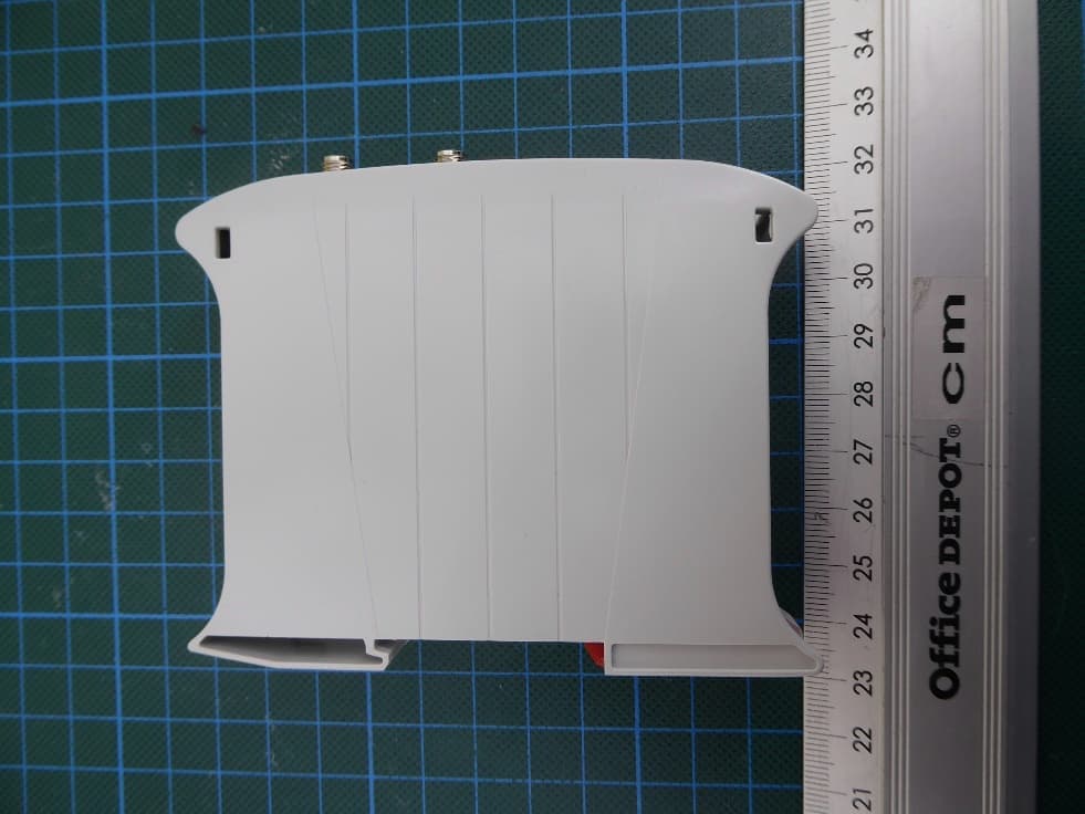
Click to zoom
Application Details
- Equipment Class
- DTS - Digital Transmission System
- Date of Grant
- Apr 10, 2026
- Application Purpose
- Original Equipment
- Equipment Note
- WBSLink - Wireless gateway for ON-Blade Sensors
- Frequency Range
- 913.00000000 - 913.00000000
- Country
- Austria
Documents & Files
Document Text
Text extracted from the exhibit documents filed with the FCC. Open a document above to read the original.
Users Manual
eologix sensor technology gmbh Kratkystrasse 2 | 8020 Graz | Austria Created on 09/10/2018 Language EN Last update 06/02/2023 OPERATION AND SERVICE MANUAL Sensor system Base station BET214 Ice sensor CET214 OperationandServiceManual_V1_4_EN_eologix © eologix sensor technology gmbh 2023 eologix.com 2 | 125 Disclosure and reproduction of this documentation as well as processing and sharing its content are prohibited, unless explicitly permitted. Any breach or infringement will result in liability for damages. All rights reserved, especially for the event of grant of a patent or registration of a utility model. © eologix sensor technology gmbh 2023 All rights reserved. We have inspected the content of this documentation regarding accordance with the described hardware and software. Nevertheless, deviations, remaining errors and omissions cannot be excluded, which is why no liability is assumed for damages resulting from this. However, the information in this printed document is regularly revised and necessary corrections will be included in the editions to follow. We appreciate any suggestions for improvement. Technical modifications reserved! PREFACE We thank you for your trust and for choosing our product. Our product has been designed and manufactured in accordance with Europeans norms and regulations. Please read this operation manual carefully before commissioning/use. Please contact us in the event of uncertainties, questions or damages to the product. Anybody who in any way works with this product must have read, understood and accepted this document and implement it to the best of their knowledge and belief. OperationandServiceManual_V1_4_EN_eologix © eologix sensor technology gmbh 2023 eologix.com 3 | 125 TABLE OF CONTENTS 1 Introduction .......................................................................................................................................... 11 1.1 Contact information manufacturer ................................................................................................. 11 1.2 Identification ........................................................................................................................................ 11 1.3 Marking ................................................................................................................................................ 12 1.4 Technical specifications .................................................................................................................. 12 1.5 Copyright ............................................................................................................................................. 13 1.6 Liability ................................................................................................................................................. 13 1.7 Content and purpose of this documentation ............................................................................. 13 2 Limit of use .......................................................................................................................................... 15 2.1 Intended use ....................................................................................................................................... 15 2.2 Reasonably foreseeable misuse ................................................................................................... 16 2.3 Limits of the product ......................................................................................................................... 17 2.4 Target group and prior knowledge .............................................................................................. 18 2.5 Principle ............................................................................................................................................... 19 3 Safety .................................................................................................................................................. 20 3.1 Safety instructions ........................................................................................................................... 20 3.1.1 Structure of safety instructions .............................................................................................. 21 3.1.2 Signal words used in safety instructions ............................................................................... 22 3.1.3 Warning, mandatory and prohibition signs used in safety instructions ........................ 23 3.2 Notices ................................................................................................................................................ 25 3.3 Information ......................................................................................................................................... 25 3.4 Residual risks ..................................................................................................................................... 26 3.4.1 Base station .................................................................................................................................. 26 3.4.2 Residual risk sensor.................................................................................................................... 29 3.5 General safety instructions and regulations............................................................................... 31 3.6 Personal protective equipment .................................................................................................... 32 3.7 Warning, mandatory and prohibition signs on the product .................................................. 33 3.7.1 Notices on the base station ...................................................................................................... 34 OperationandServiceManual_V1_4_EN_eologix © eologix sensor technology gmbh 2023 eologix.com 4 | 125 3.7.2 Notices on the sensor ................................…
Text truncated - open the document above for the full version.
Users Manual
1 | 4 eologix sensor technology flexco eologix-ping.com Waagner-Biro-Strasse 124 E: [email protected] FN420349k Stmk. Bank & Sparkassen AG 8020 Graz | Austria T: +43 (0)316 931 215 100 CEO: DI Dr. Thomas Schlegl IBAN AT93 2081 5000 4016 6647 VAT-ID: ATU68883336 BIC STSPAT2GXXX eologix sensor technology flexco, Waagner-Biro-Strasse 124, 8020 Graz, Austria User Manual Product: WBSLink – Eologix Wireless Receiv Manufacturer: eologix sensor technology gmbh 1 Product Overview The WBSLink wr is part of the eologix wireless blade monitoring system for wind turbines. The system consists of several wireless blade sensors installed on rotor blades and a receiver unit installed inside the turbine nacelle. The sensors measure parameters such as: • ice formation on rotor blades • surface temperature • optional pitch angle measurements and other physical quantities The measured data is transmitted wirelessly to the WBSLink and then forwarded to a host system for processing and visualization. The system allows wind turbine operators to detect icing conditions and automatically trigger protective actions such as turbine shutdown or restart when blades are ice-free. 2 Intended Use The device is intended to be used as part of the eologix wireless on-blade sensor system for wind turbines. The system detects icing on rotor blades and supports turbine control functions such as: • ice detection (turbine stop) • automatic restart after ice melting • optional monitoring of ice load and pitch angle measurements and other physical quantities The product must only be used under the conditions described in this manual and in accordance with applicable safety regulations. 3 System Components The complete system typically consists of: • Wireless on-blade sensors installed on rotor blades • Wireless receiver (WBSLink) installed inside the turbine • Host system or industrial PC for data processing and monitoring The sensors transmit measurement data wirelessly to the receiver. The receiver processes the incoming data packets and forwards them to the monitoring system via wired communication interfaces. 2 | 4 eologix sensor technology flexco eologix-ping.com Waagner-Biro-Strasse 124 E: [email protected] FN420349k Stmk. Bank & Sparkassen AG 8020 Graz | Austria T: +43 (0)316 931 215 100 CEO: DI Dr. Thomas Schlegl IBAN AT93 2081 5000 4016 6647 VAT-ID: ATU68883336 BIC STSPAT2GXXX 4 Installation and Setup Installation of the system must be performed by trained and authorized personnel. General setup procedure: 1. Install the receiver unit in a dry and protected location inside the wind turbine (typically part of a control box or eologix on-blade base station. 2. Connect the power supply and communication interface. 3. Connect the external antennas to the RF antenna ports. 4. Install blade sensors according to the sensor installation instructions. 5. Power on the system and verify communication between sensors and receiver. Commissioning of the system may only be performed by qualified personnel trained by the manufacturer. 5 Operation During operation, the blade sensors periodically transmit measurement data to the receiver. The WBSLink performs the following functions: • receives wireless sensor data packets • processes and validates the received information • forwards measurement data to the host system • enables synchronized measurements across multiple sensors by sending sync pulses Status LEDs on the device indicate system operation, communication activity, and network connectivity. 6 Maintenance The device requires minimal maintenance. Recommended measures include: • periodic inspection of cables and antenna connections • verification of system status indicators • ensuring proper power supply Maintenance and repair work may only be carried out by qualified personnel. 7 Safety Information The product must only be installed and operated by trained personnel. Improper installation or modification of the device may lead to equipment damage or unsafe operating conditions. Do not modify the device hardware or antennas. Only manufacturer-approved components may be used. 3 | 4 eologix sensor technology flexco eologix-ping.com Waagner-Biro-Strasse 124 E: [email protected] FN420349k Stmk. Bank & Sparkassen AG 8020 Graz | Austria T: +43 (0)316 931 215 100 CEO: DI Dr. Thomas Schlegl IBAN AT93 2081 5000 4016 6647 VAT-ID: ATU68883336 BIC STSPAT2GXXX 8 FCC Compliance Statement This device complies with Part 15 of the FCC Rules. Operation is subject to the following two conditions: 1. This device may not cause harmful interference. 2. This device must accept any interference received, including interference that may cause undesired operation. Changes or modifications not expressly approved by the party responsible for compliance could void the user’s authority to operate the equipment. To comply with the FCC radiation exposure limits set forth for an uncontrolled environment the external antennas must be fixed installed to assure a minimum separation distance of at least 20 cm to any human body. 9 ISED Canada Compliance Statement This device complies with Innovation, Science and Economic Development Canada license-exempt RSS standards. Operation is subject to the following two conditions: 1. This device may not cause interference. 2. This device must accept any interference, including interference that may cause undesired operation of the device. L’émetteur/récepteur exempt de licence contenu dans le présent appareil est conforme aux CNR d’Innovation, Sciences et Développement économique Canada applicables aux appareils radio exempts de licence. L’exploitation est autorisée aux deux conditions suivantes: 1. L’appareil ne doit pas produire de brouillage; 2. L’appareil doit accepter tout brouillage radioélectrique subi, même si le brouillage est susceptible d’en compromettre le fonctionnement. To comply with the ISED RSS-102 radiation exposure limits set forth for an uncontrolled environment the external antennas must …
Text truncated - open the document above for the full version.
Attestation Statements
SPE-24-8-237-B Part No: FG.91.A Description 915MHz 7dBi Panel Antenna With 300mm RG-58 Pigtail and N-Type (M) Connector Features: High-performance 7dBi 915MHz Panel Antenna Includes Wall/Pole Mounting Plate and Bolts Dimensions: 190 x 190mm x 25mm Cable: 300mm of RG-58 Connector: N-Type (Male) RoHS & Reach Compliant 2 www.taoglas.com SPE-24-8-237-B 1. Introduction 3 2. Specification 4 3. Mechanical Drawing 5 4. Installation Guide 6 5. Packaging 7 6. Antenna Characteristics 9 7. Radiation Patterns 13 Changelog 15 Taoglas makes no warranties based on the accuracy or completeness of the contents of this document and reserves the right to make changes to specifications and product descriptions at any time without notice. Taoglas reserves all rights to this document and the information contained herein. Reproduction, use or disclosure to third parties without express permission is strictly prohibited. 3 www.taoglas.com SPE-24-8-237-B 1. Introduction This Taoglas High Gain ISM Panel Antenna Series The Taoglas FG Series of compact 868MHz and 915MHz Panel Antennas are specially designed to provide directional wireless communication for ISM band applications The panel design combines a sleek, low-profile design with high-performance, delivering superior performance characteristics. Focused on high- performance signal transmission and reception, they are perfect for applications requiring long range, resilient connections. The FG.81 covers 868MHz with a peak gain of up to 6dBi and the FG.91 operated at 915MHz with a 7dBi peak gain. Both antennas in the series exhibit exceptional efficiencies of approx. 90% at the centre bands. Typical Applications Include: • Industrial Wireless Communication • Environmental and Agricultural monitoring • Medical and Healthcare • RFID Systems for Asset Tracking and Access Control The IP67 waterproof rated antenna enclosure is made from UV resistant ABS making it ideal for use in challenging environments and wide temperature ranges. It is supplied with a robust mounting bracket that allows for pole or wall mounting. The FG Series is supplied with RG-58 cable and N-Type connectors as standard, both of which can be fully customised to suit your requirements pending MOQ. For further information or samples please contact your regional Taoglas customer support team. 4 www.taoglas.com SPE-24-8-237-B 2. Specification RFID/ISM Electrical Band Frequency (MHz) Efficiency (%) Average Gain (dB) Peak Gain (dBi) HPBW (degrees) FtB Ratio (dB) Impedance Polarization Radiation Pattern Max. input power 915MHz 902-928 87.47 -0.58 7.68 63 @ H 69 @ V 15 max. 50 Ω Linear Directional 10W Mechanical Dimensions 190 x 190 x 25mm Material ABS Connector N Type (M) Cable 300mm RG-58 Environmental Operation Temperature -40°C to 85°C Storage Temperature -40°C to 85°C Waterproof IP67 Relative Humidity Non-condensing 65°C 95% RH 5 www.taoglas.com SPE-24-8-237-B 3. Mechanical Drawing 6 www.taoglas.com SPE-24-8-237-B 4. Installation Guide 7 www.taoglas.com SPE-24-8-237-B 5. Packaging Bracket set 1 Pcs per zipper bag 1 pcs per PE bag Bag dimensions: 300 x 260mm 1pcs per box Box dimensions: 200 x 200 x 50mm Weight: 0.74Kg 8 www.taoglas.com SPE-24-8-237-B 20pcs per carton Carton dimensions: 560 x 430 x 220mm Weight: 15.7Kg 9 www.taoglas.com SPE-24-8-237-B 6. Antenna Characteristics 6.1 Test Setup VNA Test Set-up 10 www.taoglas.com SPE-24-8-237-B 6.2 Return Loss 6.3 VSWR 11 www.taoglas.com SPE-24-8-237-B 6.4 Efficiency 6.5 Average Gain 12 www.taoglas.com SPE-24-8-237-B 6.6 Peak Gain 13 www.taoglas.com SPE-24-8-237-B 7. Radiation Patterns 7.1 Test Setup Chamber Test Set-up 14 www.taoglas.com SPE-24-8-237-B 7.2 Patterns at 915 MHz XZ Plane YZ Plane XY Plane 15 www.taoglas.com SPE-24-8-237-B Changelog for the datasheet SPE-24-8-237 – FG.91.A Revision: B (Current Version) Date: 2025-06-10 Notes: Updated performance table. Author: Paul Liu Previous Revisions Revision: A Date: 2024-09-25 Notes: Initial Datasheet Release Author: Gary West 16 www.taoglas.com SPE-24-8-237-B Mouser Electronics Authorized Distributor Click to View Pricing, Inventory, Delivery & Lifecycle Information: Taoglas: FG.91.A
Attestation Statements
SPE-12-8-061/H/PK Page 1 of 11 SPECIFICATION Part No. : OMB.915.B03F21 Description : Barracuda - 915MHz 3dBi ISM Band Indoor/Outdoor Omnidirectional Antenna Features : Omni-Directional Radiation Pattern Collinear 3.5 dBi Peak Gain Efficiency > 61% Robust Design for all Weather operation IP65 Waterproof Length: 320mm, Weight: 350g Connector: N-type Female Wall/Pole Mount Bracket Included RoHS compliant SPE-12-8-061/H/PK Page 2 of 11 1. Introduction The OMB.915.B03F21 is a fiberglass omnidirectional outdoor antenna, operating in the 902-915MHz ISM band, is designed to offer long distance coverage. The antenna is designed for applications such as metering, industrial / environmental monitoring, remote asset monitoring, and mesh network applications. The OMB.915 operates at 915MHz, one of the most widely used license free ISM bands, with a 3.5dBi peak gain. The omnidirectional antenna radiates uniformly in the azimuth. This collinear design characteristic provides the best performance, giving optimized coverage and therefore longer range in the horizontal plane over 360 degrees, thus minimizing the amount of nodes needed for a mesh network. The UV resistant fiberglass housing enables the OMB antenna to be utilized in all kinds of harsh environments, making it more robust and safer than traditional whip antennas. It can be connected directly to the access point or telemetry unit, or can be mounted on wall or device surface via the N-type connector. SPE-12-8-061/H/PK Page 3 of 11 2. Specification ELECTRICAL Standard ISM 915 Band 902~928MHz Antenna Type Collinear Gain(max) 3.5dBi Polarization Vertical Impedance 50 ohms Max Input Power 50 watts VSWR <1.5:1 Radiation Omnidirectional Vertical Bandwidth 78 Deg Horizontal Bandwidth 360 Deg Antenna Design Dipole Array Internal Material Copper Connector N Type Female MECHANICAL Length 320mm(Max) Bracket Dimension 70*35mm(Max) Radome Diameter 24mm Antenna Weight 280g Mounting Accessories 70g Application Indoor/Outdoor Radome Material White Fiberglass Mount Style Pole Mount/Wall Mount Mounting Stainless Steel Wind Resistance >150mph (>241km/h) Waterproof IP65 ENVIRONMENTAL Storage Temperature -40°C to +80°C Operating Temperature -40°C to +60°C Operating Humidity 10%~90% non-condensing Storage Humidity 5%~90% non-condensing SPE-12-8-061/H/PK Page 4 of 11 3. Antenna Characteristics 3.1 Return Loss 3.2 Maximum Gain SPE-12-8-061/H/PK Page 5 of 11 3.3 Average Gain 3.4 Efficiency SPE-12-8-061/H/PK Page 6 of 11 4. 3D Radiation Property Z X Y SPE-12-8-061/H/PK Page 7 of 11 XY Plane XZ Plane X Y Z X SPE-12-8-061/H/PK Page 8 of 11 5. Drawing SPE-12-8-061/H/PK Page 9 of 11 6. Packaging SPE-12-8-061/H/PK Page 10 of 11 7. Antenna Installation Guide SPE-12-8-061/H/PK Page 11 of 11 Taoglas makes no warranties based on the accuracy or completeness of the contents of this document and reserves the right to make changes to specifications and product descriptions at any time. Taoglas reserves all rights to this document and the information contained herein. Reproduction, use or disclosure to third parties without express permission is strictly prohibited. Copyright © Taoglas
Attestation Statements
SPE-22-8-119-A Barracuda Part No: OMB.915.B05F21 Description: 915MHz 5.9dBi Omni Antenna, with N Type Female Connector Features: Suitable to use in Robust Outdoor Environment 5.9dBi Peak Gain – optimized for Helium Mining Connector: N Type Female Dimensions: 1094.55mm x Ø26.6mm Wall and Pole Mount RoHS and REACH C ompliant 2 SPE-22-8-119-A www.taoglas.com Taoglas makes no warranties based on the accuracy or completeness of the contents of this document and reserves the right to make changes to specifications and product descriptions at any time without notice. Taoglas reserves all rights to this document and the information contained herein. Reproduction, use or disclosure to third parties without express permission is strictly prohibited. 1. Introduction 3 2. Specifications 4 3. Antenna Characteristics 5 4. Radiation Patterns 7 5. Mechanical Drawing 9 6. Packaging 10 7. Antenna Installation Guide 11 Changelog 12 3 SPE-22-8-119-A www.taoglas.com The Barracuda OMB.915.B05F21 is a fiberglass omnidirectional outdoor antenna, operating in the 915MHz ISM band and is designed to offer long distance coverage. The antenna is designed for applications such as metering, industrial & environmental monitoring, remote asset monitoring and mesh network applications. The 915MHz band is one of the most widely used license free ISM bands. Typical applications are in SigFox, Helium, LoRa and LPWA networks. With a 5.9dBi peak gain, the OMB.915.B05F21omnidirectional antenna radiates uniformly in the azimuth. This collinear design characteristic provides the best performance, giving optimized coverage and therefore longer range in the horizontal plane over 360 degrees, thus minimizing the amount of nodes needed for a mesh network. The UV resistant fiberglass housing enables the OMB antenna to be utilized in all kinds of harsh environments making it more robust and safer than traditional whip antennas. It can be connected directly to the access point or telemetry unit or can be mounted on wall or device surface via the N-type connector and a pole-mount and wall-mount bracket is included. This antenna is an ideal product for developing your own Helium Network on the 915MHz spectrum. Custom antenna modifications are subject to possible NRE and minimum order quantity. For further information please contact your regional Taoglas customer support team. 1. Introduction 4 SPE-22-8-119-A www.taoglas.com Electrical Frequency (MHz) Band Efficiency (%) Average Gain (dB) Peak Gain (dBi) Impedance Polarization Radiation Pattern Max Input Power 915MHz 902-928 75.7 -1.21 5.9 50Ω Linear Omni 30W Mechanical Length 1094±30mm Bracket Dimension 70*54mm Radome Diameter 24mm Antenna Weight 500g Mounting Accessories 70g Application Indoor/Outdoor Radome Material White Fiberglass Mount Style Pole Mount/Wall Mount Mounting Stainless Steel Wind Resistance >150mph (>241km/h) Waterproof IP65 E nvironmental Storage Temperature -20°C to +80°C Operating Temperature -20°C to +60°C Operating Humidity 10%~80% Non-condensing Storage Humidity 5%~80% Non-condensing 2. Specifications 5 SPE-22-8-119-A www.taoglas.com 3.1 Return Loss 3.2 Efficiency 3. Antenna Characteristics 6 SPE-22-8-119-A www.taoglas.com 3.3 Average Gain 3.4 Peak Gain 7 SPE-22-8-119-A www.taoglas.com 4. 4.1 Test Setup Free space 4. Radiation Patterns X Y Z 8 SPE-22-8-119-A www.taoglas.com 4.2 915MHz_2D & 3D Radiation Patterns XY Plane XZ Plane YZ Plane 9 SPE-22-8-119-A www.taoglas.com 5. Mechanical Drawing ( Units: mm) 10 SPE-22-8-119-A www.taoglas.com 10pcs OMB.915.B05F21 per carton Dimensions - 1170*410*180mm 1pcs OMB.915.B05F21 per Tube Dimensions – Ø80*1150 6. Packaging 180mm 410mm 1170mm 11 SPE-22-8-119-A www.taoglas.com 7. Antenna Installation Guide 12 SPE-22-8-119-A www.taoglas.com 13 SPE-22-8-119-A www.taoglas.com Changelog for the datasheet SPE-22-8-119 – OMB.915.B05F21 Revision: A (Initial Release) Date: 2022-08-02 Changes: Initial Release Changes Made by: Gary West Previous Revisions 14 SPE-22-8-119-A www.taoglas.com www.taoglas.com © Taoglas
Attestation Statements
To: Federal Communications Commission 7435 Oakland Mills Road Columbia, MD 21046 USA FCC ID: 2APYI-WBSL22 Part 15 – PROFESSIONAL INSTALLATION ATTESTATION The applicant eologix sensor technology flexco hereby declares that the requirements of KDB 353028 D01 Antennas Part 15 Transmitters v01r01 have been met and shown on the following questions. 1. Professional installation must be justified. Description: The WBSLink is part of the eologix wireless blade monitoring system for wind turbines. The system consists of several wireless blade sensors installed on rotor blades and a receiver unit installed inside the turbine nacelle. 2. Professional installation does not permit use of any antenna with the transmitter; the permitted types of antenna specified as below. Description: The device will be marketed with the below listed antennas that are covered by the FCC compliance measurements and documented accordingly with antenna data sheets: External 7 dBi Panel Antenna with SMA connector TAOGLAS FG.91.A External 5.9 dBi Dipole Antenna with N-type female connector TAOGLAS OMB.915.B05F21 External 3.5 dBi Dipole Antenna with N-type female connector TAOGLAS OMB.915.B03F21 3. The applicant should address the following items when justifying professional installation. (1) To qualify for professional installation, please explain why the hardware is not readily available to average consumer. Description: This device cannot be used by consumer because it communicates only with the on- blade sensors (913 MHz, one channel, proprietary) and will not be sold directly to the general public through retail store, therefore the hardware is not readily available to average consumer. (2) Marketing — Applicant must ensure device cannot be sold via retail to the general public or by mail order. Description: This product is not available to consumers and will not be sold directly to the general public through retail store. It will be sold to authorized dealers or installers only. (3) Applicant must show that device intended use is not for consumers and general public. Description: This device is exclusively for used in the industrial/commercial environment (wind power plants). It is intended to be used only as part of the eologix wireless on-blade sensor system for wind turbines. The system detects icing on rotor blades, temperatures, acceleration and supports turbine control functions. (4) Explain what is unique, sophisticated, complex, or specialized about the equipment that REQUIRES it to be installed by a professional installer? Description: The WBSLink must be installed inside the turbine nacelle – the external antennas will be installed with site-specific antenna cable routings either inside or outside on the turbine housing. The entire installation is subject to professional engineers. 4. Other professional installation requirements (1) Installation must be controlled. Description: The installation and later maintenance are fully under control of the wind power plant operator with their special trained professional installers. If you have any questions, please feel free to contact me. Yours sincerely, Authorized Agent
Cover Letter(s)
EOLOGIX-PING eologix sensor technology flexco, Waagner-Biro-Strasse 124,8020 Graz, Austria PHOENIX TESTLAB GmbH Product Certification Department Koenigswinkel 10 32825 Blomberg, Germany Power of Attorney To Whom It May Concern: Please be advised that we, eologix sensor technology flexco, authorize the following persons from PHOENIX TESTLAB GmbH: - Sabrina Berghahn - Bernd Steiner to act on our behalf in all matters relating to application for equipment authorization, including the signing of all documents relating to these matters in the following countries: USA and Canada PHOENIX TESTLAB GmbH has our permission to use our technical documents for the approvals for the following name device: Product decription: WBSLink - Wireless gateway for On-Blade Sensors FCC ID: 2APYI-WBSL22 1C: 24932-WBSL22 HVIN:WBSL22 PMN: WBSLink FVIN: WBSL22-W913-26 Unless future correspondence from eologix sensor technology gmbh please extend your full cooperation to PHOENIX TESTLAB GmbH regarding matters to the above mentioned products to 12 months after the signatory date of this authorization. Contact person Michael Moser Position in the companyCTO Dafe of signatory 26.02.2026 Signatory (signature of the applicant) eologix sensor technology flexco Waagner-Biro-Strasse 124 8020 Graz | Austria eologix-ping.com E: [email protected] T:+43 (0)316 931215 100 FN420349k CEO: DI Dr. Thomas Schlegl VAT-ID: ATU68883336 Stmk. Bank & Sparkassen AG IBAN AT93 2081 5000 4016 6647 BIC STSPAT2GXXX i|i
Cover Letter(s)
Long/Short-term Confidentiality Request To: Federal Communications Commission 7435 Oakland Mills Road Columbia, MD 21046 USA FCC ID: 2APYI-WBSL22 To Whom It May Concerns, Pursuant to sections 0.457(d) and 0.459 of CFR 47 and to avoid premature release of sensitive information prior to marketing or release of the product to the public, the Grantee hereby requests long-term confidential treatment of information accompanying this application as outlined below: ☒ Schematics ☒ Parts List ☒ Block Diagram ☐ Tune-Up Info ☒ Operational Description In addition, the Grantee requests the following exhibits contained in this application to be temporarily (short-term confidentiality) withheld from the public disclosure ☐ for an initial period of days ☐ until: ☒ not applicable ☐ External Photos ☐ Test Setup Photos ☐ Internal Photos ☐ Users Manual The above materials contain trade secrets and proprietary information not customarily released to the public. The public disclosure of these matters might be harmful to the applicant and provide unjustified benefits to its competitors. The applicant understands that pursuant to rule 0.457(d), disclosure of this application and all accompanying documentation will not be made before the date of the GRANT for this application. If you have any questions, please feel free to contact me. Yours sincerely, Authorised Agent
External Photos
External photos Examiner:Mohamed Yassine KHALEK Date of issue: 09.04.2026Order Number: 25-111882page 1 of 3 EUTfront view EUTrear view External photos Examiner:Mohamed Yassine KHALEK Date of issue: 09.04.2026Order Number: 25-111882page 2 of 3 EUTtop view EUTbottom view External photos Examiner:Mohamed Yassine KHALEK Date of issue: 09.04.2026Order Number: 25-111882page 3 of 3 EUTside view 1 EUT side view 2
ID Label/Location Info
1 | 1 eologix sensor technology flexcoeologix-ping.com Waagner-Biro-Strasse 124E: [email protected]. Bank & Sparkassen AG 8020 Graz | AustriaT: +43 (0)316 931 215 100CEO: DI Dr. Thomas SchleglIBAN AT93 2081 5000 4016 6647 VAT-ID: ATU6888…
Text truncated - open the document above for the full version.
Contact Information
Applicant
Michael Moser(Managing Director)
[email protected]Fax: +43-316-931215200
Technical Contact
FCC US Agent LLCTim Payne
3722 Illinois Avenue, · Saint Charles, Illinois, 60174 · Germany
Test Firm
PHOENIX TESTLAB GmbHHolger Bentje
[email protected]Fax: 49-5235-9500-28
Technical Specifications
| # | Rule Parts | Frequency Range | Power Output |
|---|---|---|---|
| 1 | 15C | 913 MHz - 913 MHz | 3.30 mW |
Other Applications from eologix sensor technology gmbh
2APYI-WBSU26
Aug 19, 2026WBS - Wireles ON-Blade Sensor
Equipment Class
DTS - Digital Transmission System