2APZ9RP12BLINX TPMS MODULE
Vision Automotive Technology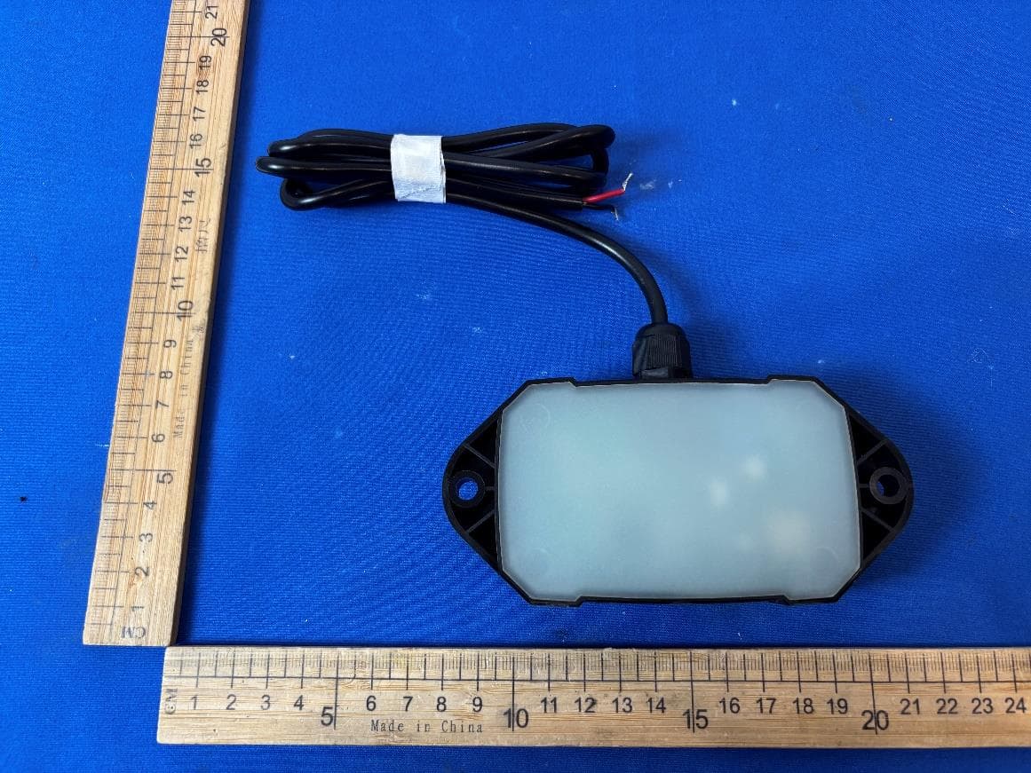
Click to zoom
Application Details
- Equipment Class
- DTS - Digital Transmission System
- Date of Grant
- Jun 03, 2026
- Application Purpose
- Original Equipment
- Equipment Note
- LINX TPMS MODULE
- Frequency Range
- 2402.00000000 - 2480.00000000
- Company
- Vision Automotive Technology
- Country
- Australia
Documents & Files
Document Text
Text extracted from the exhibit documents filed with the FCC. Open a document above to read the original.
Users Manual
LINX TPMS MODULE Part Number: Latest Revision Date: 01/04/2019 Page 1 of 2 Fitting Instruction Number: 3789891 QUICK START GUIDE This module enables communication between ARB LINX and the ARB TPMS sensors. Installation The LINX TPMS Module should be positioned in a fairly central location in the vehicle, equidistant for all wheels. This will ensure the best performance from all TPMS tyre sensors. Under the armrest centre console is a good location. It is a central location and in most vehicles it also has 12VDC outlet which can be used to power the module. The LINX TPMS module should be secured in place using at least one of the screw holes or using cable ties. Test for a 12VDC circuit that turns on when the vehicle key is in the ACC or ON position. The circuit must also be off when the vehicle key is in the off position, hence not a permanent battery connection or else the module will continue to draw power from the vehicle battery when the vehicle is turned off. Connect the RED wire to this circuit using a suitable method such as an insulated wire tap, or a solder and tap. A 12VDC power outlet or cigarette lighter socket provides this functionality and is the ideal place to piggy back power from. Connect the BLACK wire to the vehicle ground. Connection to LINX To connect the LINX TPMS module to LINX, turn the vehicle key to the ACC position so that both the TPMS module and LINX are on. Navigate LINX to the main icon screen and activate the TPMS module. In the TPMS module settings screen, tap the ‘Connect to TPMS’ button, and select your TPMS module from the list. When connected the vehicle icon on the TPMS module will be highlighted as shown. To learn the TPMS tyre sensors that are associated to your vehicle follow the instructions in the latest LINX Operation Guide. 7450126 LINX TPMS MODULE Part Number: Latest Revision Date: 01/04/2019 Page 2 of 2 Fitting Instruction Number: 3789891 ARB PRODUCTS WARRANTY AGAINST DEFECTS ARB warrants the ARB Products against defects in workmanship and materials for the Warranty Period. If defective workmanship or materials become apparent in the Warranty Period, ARB will replace or repair the defective Product. The benefits to the customer given by this warranty are in addition to other rights and remedies of the customer under a law in relation to the goods or services to which the warranty relates. 1) In this warranty: • ARB means ARB Corporation Limited (ABN 31 006 708 756) of 42-44 Garden St, Kilsyth Victoria 3137 • ARB Outlet means an outlet which has been authorised by ARB to sell and fit ARB Products • ARB Product means products which ARB manufacturers or for which ARB is the exclusive supplier • Product Information means the information about the relevant ARB Product which may be contained in any of: documentation provided with the ARB Product, owner’s manual, operating manual, service manual or the manufacturer’s manual or labels attached to the ARB Product • Warranty Period means, in respect of an ARB Product, the period that this warranty against defects applies and which is set out in paragraph 8. 2) To be entitled to claim the warranty, the customer must: a) have the ARB Product fitted in accordance with the Product Information b) carry out normal care and maintenance of the ARB Product, including any required by the Product Information c) provide proof of purchase of the ARB Product d) make the claim in the Warranty Period. 3) The warranty will not apply in circumstances where the defect is caused by: a) unusual, improper or negligent use or misuse of the ARB Product b) incorrect fitting of the ARB Product other than at an ARB Outlet c) use of non-genuine ARB components in or with the ARB Product d) use of the ARB Product outside of the requirements of the Product Information. 4) The procedure for the customer to claim the warranty is: a) return the ARB Product to the nearest ARB Outlet or contact ARB to arrange a time to bring a vehicle fitted with the ARB Product to an ARB Outlet for inspection. Contact details are in paragraph 7 below if further information is required regarding local outlet details b) bring proof of purchase of the ARB Product to the ARB Outlet c) ARB will review the ARB Product and advise whether the conditions of this warranty have been met 5) Where ARB accepts a customer’s warranty claim, ARB will rectify any defective workmanship or materials at its own expense. 6) Expenses incurred by the customer in claiming the warranty are to be borne by the customer. 7) This warranty is given by: ARB Corporation Limited 42-44 Garden Street Kilsyth VIC 3137, Australia. Phone: 03 9761 6622. Fax: 03 9721 9090. www.arb.com.au 8) The period within which a defect in the ARB Products must appear if the customer is to be entitled to claim the warranty is 3 years starting on the date of purchase unless: The ARB Product is used in Commercial Use. Commercial Use means use in industry or commerce including (without limitation) use in the mining industry or as a hire vehicle. In this case, the Warranty Period is 1 year 9) The warranty against defects contained in this document replaces any other warranty against defects or voluntary warranty given in relation to the Products. Our goods come with guarantees that cannot be excluded under the Australian Customer Law. You are entitled to a replacement or refund for a major failure and compensation for any other reasonably foreseeable loss or damage. You are also entitled to have the goods repaired or replaced if the goods fail to be of acceptable quality and the failure does not amount to a major failure. USA - FCC Statement This device complies with part 15 of the FCC Rules. Operation is subject to the following two conditions: (1) this device may not cause harmful interference, and (2) this device must accept any interference received, including interference that may cause undesired operation. This equipment has been tested and found to comply with the limits for a Class B digital device, p…
Text truncated - open the document above for the full version.
Attestation Statements
* the applicant must designate a contact located in the United States for purposes of acting as the applicant’s agent for service of process, regardless of whether the applicant is a domestic or foreign entity. An applicant located in the United States may designate itself as the agent for service of process. SC6059116 U.S. Agent Designation for Service of Process - Certification Attestation Letter 5/28/2026 TO: Federal Communications Commission 7435 Oakland Mills Road Columbia, MD 21046 ATTN.: Reviewing Engineer FCC ID: 2APZ9RP12B FRN of applicant: 0027526631 Per section 2.911(d)(7) of the FCC rules, Vision Automotive Technology FRN:0027526631(“the applicant”) certifies that the equipment for which authorization is sought is designated to thefollowing U.S. agent* for service of process: Company Name: Global Product Services and Consultation LLC FCC Registration Number (FRN): 0033406703 Physical U.S. Company Address: 328 W Palm Ave. Monrovia, CA91016 Contact Person: Michael Chan Tel: +1 626 366 4358 Agent Email Address: [email protected] The above contact person accepts the obligation for service of process. The applicant accepts to maintain an agent for no less than one year after the grantee has terminated all marketing and importation or the conclusion of any Commission-related proceeding involving the equipment. Applicant Signed:Agent Signed (if different from Applicant): Signed: Printed name: Daniel Regodeiro Title: Project Engineer Company Name: Vision Automotive Technology Date: 5/28/2026 Signed: Printed name: Michael Chan Title: Technical Director Company Name: Global Product Services and Consultation LLC Date: 5/29/2026
Attestation Statements
Vision Automotive Technology 2026-05-20 Eurofins Electrical and Electronic Testing NA, Inc. 914 West Patapsco Avenue Baltimore, MD 21230 RE: Attestation Statements Part 2.911(d)(5)(i) request for (FCC ID: 2APZ9RP12B ) [Vision Automotive Technology] (“the applicant”) certifies that the equipment for which authorization is sought is not“covered” equipment prohibited from receiving an equipment authorization pursuant to section 2.903 of the FCC rules. We also certify that, as of the date of the filing of the application, the equipment does not utilize cyber-security or anti-virus software from Kaspersky Lab, Inc, or any of its successors and assignees, which is also on the “covered list”. Sincerely, Daniel Regodeiro Project Engineer Vision Automotive Technology 600 Waterdale Road, Heidelberg West, Melbourne, 3081 Australia Vision Automotive Technology 2026-05-20 Eurofins Electrical and Electronic Testing NA, Inc. 914 West Patapsco Avenue Baltimore, MD 21230 RE: Attestation Statements Part 2.911(d)(5)(ii) request for (FCC ID: 2APZ9RP12B ) [Vision Automotive Technology] (“the applicant”) certifies that, as of the date of the filing of the application, the applicant is notidentified on the Covered List as an entity producing “covered” equipment. Sincerely, Daniel Regodeiro Project Engineer Vision Automotive Technology 600 Waterdale Road, Heidelberg West, Melbourne, 3081 Australia
Cover Letter(s)
Vision Automotive Technology 2026-05-20 Eurofins Electrical and Electronic Testing NA, Inc. 914 West Patapsco Avenue Baltimore, MD 21230 RE: LETTER OF AGENT AUTHORIZATION To Whom It May Concern: We, the undersigned, hereby authorizeGuangdong Global Testing Technology Co., Ltd.to act on our behalf in all matters relating to application for equipment authorization, including the signing of all documents relating to these matters. We also hereby certify that no party to the application authorized hereunder is subject to the denial of benefits, including FCC benefits, pursuant to Section 5301 of the Anti-Drug Abuse Act of 1988, 21 U.S.C.853(a). This agreement expires one year from the current date. Sincerely, Daniel Regodeiro Project Engineer Vision Automotive Technology 600 Waterdale Road, Heidelberg West, Melbourne, 3081 Australia
Cover Letter(s)
Vision Automotive Technology 2026-05-20 Eurofins Electrical and Electronic Testing NA, Inc. 914 West Patapsco Avenue Baltimore, MD 21230 RE: CONFIDENTIALITY REQUEST FOR (EUT Name: LINX TPMS MODULE /Model: 7450126/FCC ID: 2APZ9RP12B) To Whom It May Concern: This letter serves as an official request for confidentiality under sections0.457 and 0.459 of CFR 47. We have requested that the (Block Diagram, Operational Description, Schematics) required to be submitted with this application be permanentlywithheld from public review. The above materials contain trade secrets and proprietary information not customarily released to the public. The public disclosure of these materials may be harmful to the applicant and provide unjustified benefits to its competitors. Please contact me if there is any information you may need. Sincerely, Daniel Regodeiro Project Engineer Vision Automotive Technology 600 Waterdale Road, Heidelberg West, Melbourne, 3081 Australia
External Photos
External
ID Label/Location Info
7450126 Label: Size: 42*19mm Printing: Laser engraving Label Location: Product Name: LINX TPMS MODULE Model: 7450126 Input: DC 12~24V, 0.015A FCC ID: 2APZ9RP12B
Internal Photos
Internal Bluetooth Antenna 433MHz RX Antenna
RF Exposure Info
RF EXPOSURE EVALUATION According to FCC 1.1310: The criteria listed in the following table shall be used to evaluate the environment impact of human exposure to radio frequency(RF) Radiation as specified in ß1.1307(b) FCC ID: 2APZ9RP12B EUT Specification EUT LINX TPMS MODULE Frequency band (Operating) BT: 2.402GHz ~ 2.480GHz BLE: 2.402GHz ~ 2.480GHz WIFI: 2.412GHz ~ 2.462GHz WIFI: 5.180GHz ~ 5.240GHz WIFI: 5.260GHz ~ 5.320GHz WIFI: 5.500GHz ~ 5.700GHz WIFI: 5.745GHz ~ 5.825GHz Device category Portable (<20cm separation) Mobile (>20cm separation) Exposure classification Occupational/Controlled exposure (S = 5mW/cm 2 ) General Population/Uncontrolled exposure (S=1mW/cm 2 ) Antenna diversity Single antenna Multiple antennas Tx diversity Rx diversity Tx/Rx diversity Max. output power -1.97 dBm Antenna gain (Max) 0.5 dBi Evaluation applied MPE Evaluation SAR Evaluation Limits for Maximum Permissible Exposure(MPE) Frequency Range(MHz) Electric Field Strength(V/m) Magnetic Field Strength(A/m) Power Density(mW/cm 2 ) Average Time (A) Limits for Occupational/Control Exposures 300-1500 -- -- F/300 6 1500-100000 -- -- 5 6 (B) Limits for General Population/Uncontrol Exposures 300-1500 -- -- F/1500 6 1500-100000 -- -- 1 30 2 / 3 Friis transmission formula: Pd=(Pout*G)\(4*pi*R2) Where P d = Power density in mW/cm 2 , P out =output power to antenna in mW. G= gain of antenna in linear scale, Pi=3.1416 R= distance between observation point and center of the radiator in cm=20cm P d the limit of MPE, 1mW/cm 2 . If we know the maximum gain of the antenna and total power input to the antenna, through the calculation, we will know the distance where the MPE limit is reached. For multiple RF sources: Multiple RF sources are exempt if: in the case of fixed RF sources operating in the same time-averaging period, or of multiple mobile or portable RF sources within a device operating in the same time averaging period, if the sum of the fractional contributions to the applicable thresholds is less than or equal to 1 as indicated in the following equation Evaluated k : the maximum reported SAR or MPE of fixed, mobile, or portable RF source k either in the device or at the transmitter site from an existing evaluation at the location of exposure. Exposure Limit k : either the general population/uncontrolled maximum permissible exposure (MPE) or specific Absorption rate (SAR) limit for each fixed, mobile, or portable RF source k. 3 / 3 Measurement Result Operation Mode Channel Frequency (MHz) Max Measured Power (dBm) Tune up tolerance (dBm) Max tune up conducted power (dBm) Output Peak power (mW) Ant. Gain (dBi) Ant. Gain (numeric) Power density at 20cm (mW/ cm2) Power density Limits (mW/ cm2) Results BLE 1Mbps 2440 -1.97 -2±1 -1 0.794 0.5 1.122 0.000177 1 PASS No need to test SAR. Signature: Alan He Date: 2026-05-19
Test Report
Appendix A Duty Cycle Condition Mode Frequency (MHz) Antenna Duty Cycle (%) Correction Factor (dB) 1/T (kHz) NVNT BLE 1M 2402 Ant1 61.76 2.09 2.59 NVNT BLE 1M 2440 Ant1 61.84 2.09 2.59 NVNT BLE 1M 2480 Ant1 61.79 2.09 2.59 2 / 22 Duty Cycle NVNT BLE 1M 2402MHz Ant1 Duty Cycle NVNT BLE 1M 2440MHz Ant1 3 / 22 Duty Cycle NVNT BLE 1M 2480MHz Ant1 4 / 22 Maximum Peak Conducted Output Power Condition Mode Frequency (MHz) Antenna Conducted Power (dBm) Duty Factor (dB) Total Conducted Power (dBm) Total Conducted Power (W) Limit Conducted (dBm) Verdict NVNT BLE 1M 2402 Ant1 -2.08 0 -2.08 0.00062 30 Pass NVNT BLE 1M 2440 Ant1 -1.97 0 -1.97 0.00064 30 Pass NVNT BLE 1M 2480 Ant1 -2.09 0 -2.09 0.00062 30 Pass 5 / 22 Peak Power NVNT BLE 1M 2402MHz Ant1 Peak Power NVNT BLE 1M 2440MHz Ant1 6 / 22 Peak Power NVNT BLE 1M 2480MHz Ant1 7 / 22 -6dB Bandwidth Condition Mode Frequency (MHz) Antenna -6 dB Bandwidth (MHz) Limit -6 dB Bandwidth (MHz) Verdict NVNT BLE 1M 2402 Ant1 0.7593 0.5 Pass NVNT BLE 1M 2440 Ant1 0.7788 0.5 Pass NVNT BLE 1M 2480 Ant1 0.777 0.5 Pass 8 / 22 -6dB Bandwidth NVNT BLE 1M 2402MHz Ant1 -6dB Bandwidth NVNT BLE 1M 2440MHz Ant1 9 / 22 -6dB Bandwidth NVNT BLE 1M 2480MHz Ant1 10 / 22 Occupied Channel Bandwidth Condition Mode Frequency (MHz) Antenna 99% OBW (MHz) NVNT BLE 1M 2402 Ant1 1.0555 NVNT BLE 1M 2440 Ant1 1.0593 NVNT BLE 1M 2480 Ant1 1.0493 11 / 22 OBW NVNT BLE 1M 2402MHz Ant1 OBW NVNT BLE 1M 2440MHz Ant1 12 / 22 OBW NVNT BLE 1M 2480MHz Ant1 13 / 22 Maximum Power Spectral Density Level Condition Mode Frequency (MHz) Antenna Conducted PSD (dBm/3kHz) Duty Factor (dB) Total PSD (dBm/3kHz) Limit (dBm/3kHz) Verdict NVNT BLE 1M 2402 Ant1 -16.73 0 -16.73 8 Pass NVNT BLE 1M 2440 Ant1 -16.48 0 -16.48 8 Pass NVNT BLE 1M 2480 Ant1 -16.54 0 -16.54 8 Pass 14 / 22 PSD NVNT BLE 1M 2402MHz Ant1 PSD NVNT BLE 1M 2440MHz Ant1 15 / 22 PSD NVNT BLE 1M 2480MHz Ant1 16 / 22 Band Edge Condition Mode Frequency (MHz) Antenna Max Value (dBc) Limit (dBc) Verdict NVNT BLE 1M 2402 Ant1 -51.31 -20 Pass NVNT BLE 1M 2480 Ant1 -54.4 -20 Pass 17 / 22 Band Edge NVNT BLE 1M 2402MHz Ant1 Ref Band Edge NVNT BLE 1M 2402MHz Ant1 Emission 18 / 22 Band Edge NVNT BLE 1M 2480MHz Ant1 Ref Band Edge NVNT BLE 1M 2480MHz Ant1 Emission 19 / 22 Conducted RF Spurious Emission Condition Mode Frequency (MHz) Antenna Max Value (dBc) Limit (dBc) Verdict NVNT BLE 1M 2402 Ant1 -34.07 -20 Pass NVNT BLE 1M 2440 Ant1 -36.28 -20 Pass NVNT BLE 1M 2480 Ant1 -41.26 -20 Pass 20 / 22 Tx. Spurious NVNT BLE 1M 2402MHz Ant1 Ref Tx. Spurious NVNT BLE 1M 2402MHz Ant1 Emission 21 / 22 Tx. Spurious NVNT BLE 1M 2440MHz Ant1 Ref Tx. Spurious NVNT BLE 1M 2440MHz Ant1 Emission 22 / 22 Tx. Spurious NVNT BLE 1M 2480MHz Ant1 Ref Tx. Spurious NVNT BLE 1M 2480MHz Ant1 Emission
Test Report
TRF No.: 04-E001-0B TRF Originator: GTG TRF Date: 2023-12-13 Web: www.gtggroup.com E-mail: [email protected] Tel.: 86-400 755 8988 CFR 47 FCC PART 15 SUBPART C TEST REPORT For LINX TPMS MODULE MODEL NUMBER: 7450126 REPORT NUMBER: E04A26040774F00201 ISSUE DATE: May 19, 2026 FCC ID: 2APZ9RP12B Prepared for Vision Automotive Technology 600 Waterdale Road, Heidelberg West, Melbourne, 3081 Australia Prepared by Guangdong Global Testing Technology Co., Ltd. Room 101-105, 203-210, Building 1, No.2, Keji 8 Road, Songshan Lake Park, Dongguan city, Guangdong, People’s Republic of China, 523808 This report is based on a single evaluation of the submitted sample(s) of the above mentioned product, it does not imply an assessment of the production of the products. This report shall not be reproduced, except in full, without the written approval of Guangdong Global Testing Technology Co., Ltd. REPORT NO.: E04A26040774F00201 Page 2 of 42 TRF No.: 04-E001-0B Global Testing , Great Quality. Revision History Rev. Issue Date Revisions Revised By V0 May 19, 2026 Initial Issue REPORT NO.: E04A26040774F00201 Page 3 of 42 TRF No.: 04-E001-0B Global Testing , Great Quality. Summary of Test Results Test Item Clause Limit/Requirement Result Antenna Requirement N/A FCC Part 15.203/15.247 (c) RSS-GEN Clause 6.8 Pass AC Power Line Conducted Emission ANSI C63.10-2020, Clause 6.2 FCC Part 15.207 RSS-GEN Clause 8.8 N/A Conducted Output Power ANSI C63.10-2020, Clause 11.9.1.2 FCC Part 15.247 (b)(3) RSS-247 Clause 6.3.2 Pass 6dB Bandwidth and 99% Occupied Bandwidth ANSI C63.10-2020, Clause 11.8.1 FCC Part 15.247 (a)(2) RSS-247 Clause 6.3.1(a) ISED RSS-Gen Clause 6.7 Pass Power Spectral Density ANSI C63.10-2020, Clause 11.10.2 FCC Part 15.247 (e) RSS-247 Clause 6.3.1(b) Pass Conducted Band edge and spurious emission ANSI C63.10-2020, Clause 11.11 FCC Part 15.247(d) RSS-247 Clause 6.6 Pass Radiated Band edge and Spurious Emission ANSI C63.10-2020, Clause 11.12 FCC Part 15.247(d) FCC Part 15.205/15.209 RSS-247 Clause 6.6 RSS-GEN Clause 8.9 Pass Duty Cycle ANSI C63.10-2020, Clause 11.6 None; for reporting purposes only. Pass Note: 1. For ISED, this report is also performed according to ANSI C63.10-2020 + Cor.1-2023 + C63.10a-2024 + Errata to C63.10a-2024 standards. 2. N/A: In this whole report not applicable. *This test report is only published to and used by the applicant, and it is not for evidence purpose in China. *The measurement result for the sample received is <Pass> according to < CFR 47 FCC PART 15 SUBPART C, ISED RSS-247 Issue 4> when <Accuracy Method> decision rule is applied. REPORT NO.: E04A26040774F00201 Page 4 of 42 TRF No.: 04-E001-0B Global Testing , Great Quality. CONTENTS 1. ATTESTATION OF TEST RESULTS ..................................................................................... 5 2. TEST METHODOLOGY ......................................................................................................... 6 3. FACILITIES AND ACCREDITATION ..................................................................................... 6 4. CALIBRATION AND UNCERTAINTY ................................................................................... 7 4.1. MEASURING INSTRUMENT CALIBRATION ........................................................... 7 4.2. MEASUREMENT UNCERTAINTY ............................................................................ 7 5. EQUIPMENT UNDER TEST .................................................................................................. 8 5.1. DESCRIPTION OF EUT ........................................................................................... 8 5.2. CHANNEL LIST ........................................................................................................ 8 5.3. MAXIMUM CONDUCTED OUTPUT POWER ........................................................... 9 5.4. TEST CHANNEL CONFIGURATION ........................................................................ 9 5.5. THE WORSE CASE POWER SETTING PARAMETER ............................................ 9 5.6. DESCRIPTION OF AVAILABLE ANTENNAS ........................................................... 9 5.7. SUPPORT UNITS FOR SYSTEM TEST ................................................................... 9 5.8. SETUP DIAGRAM .................................................................................................... 9 6. MEASURING EQUIPMENT AND SOFTWARE USED......................................................... 11 7. ANTENNA PORT TEST RESULTS ..................................................................................... 13 7.1. Conducted Output Power ........................................................................................ 13 7.2. 6dB Bandwidth and 99% Occupied Bandwidth ....................................................... 14 7.3. Power Spectral Density ........................................................................................... 16 7.4. Conducted Band edge and spurious emission ........................................................ 17 7.5. Duty Cycle .............................................................................................................. 19 8. RADIATED TEST RESULTS ............................................................................................... 20 8.1. Radiated Band edge and Spurious Emission .......................................................... 26 9. ANTENNA REQUIREMENT ................................................................................................ 38 10. AC POWER LINE CONDUCTED EMISSION ......................................................... 40 11. TEST DATA - APPENDIX A ................................................................................... 42 REPORT NO.: E04A26040774F00201 Page 5 of 42 TRF No.: 04-E001-0B Global Testing , Great Quality. 1. ATTESTATION OF TEST RESULTS Applicant Information Company Name: Vision Automotive Technology Address: 600 Waterdale Road, Heidelberg West, Melbo…
Text truncated - open the document above for the full version.
Test Report
Onboard PCB antenna Features Onboard PCB antenna with small, low-profile and light-weight type. Wide bandwidth Applications Bluetooth/Wireless LAN/Home RF ISM band 2.4GHz applications Specifications Part Number Frequency Range (MHz) Peak Gain (XZ-total) Average Gain (XZ-total) VSWR Impedance PCB ANT 2400~2500 0.5dBi typ. 0dBi typ. 2.0 max. 50 Ω Dimensions Mark L W Dimensions 11.0±0.2 4.5±0.2 Return Loss-without matching circuits Radiation Patterns
Test Setup Photos
Setup Photographs Radiated Band edge and Spurious Emission .
Contact Information
Applicant
Daniel Regodeiro(Project Engineer)
[email protected]Fax: +66026719370
Technical Contact
Global Product Services and Consultation LLCMichael Chan
328 W Palm Ave. · Monrovia, California, 91016 · United States
Test Firm
Guangdong Global Testing Technology Co., Ltd.Shawn Wen
Technical Specifications
| # | Rule Parts | Frequency Range | Power Output |
|---|---|---|---|
| 1 | 15C | 2.40 GHz - 2.48 GHz | 600.00 µW |