2AQ34-LDLT002Smart Leak Sensor
Meshify Inc
Click to zoom
Application Details
- Equipment Class
- DSS - Part 15 Spread Spectrum Transmitter
- Date of Grant
- Apr 11, 2023
- Application Purpose
- Original Equipment
- Date of Application
- Apr 11, 2023
- Equipment Note
- Smart Leak Sensor
- Frequency Range
- 902.30000000 - 914.90000000
- Company
- Meshify Inc
- Country
- United States
Documents & Files
Document Text
Text extracted from the exhibit documents filed with the FCC. Open a document above to read the original.
Users Manual
The Smart Leak Sensor, part of the Meshify Defender™ sensor solution suite, detects leaks near your equipment and systems on your property. With early leak detection, either caused by frozen burst pipes, equipment or system failures, you can help prevent extensive property damage with a leak sensor. The Smart Leak Sensor communicates with the Gateway using LoRaWAN™ protocol providing you with wireless connectivity over long distances without the need for Wi-Fi. Smart Leak Sensor Cellular LoRaWAN ® Solution Help protect your property and equipment with smart leak monitoring Key Features: Product Data Sheet • Wireless, battery-powered LoRaWAN ® water sensor • Detects water on contact • IP66 (Ingress Protection) rated for protection against dust and high-pressure water jets • Easy activation and alert monitoring via the Meshify Protect app • Optional temperature probe, leak probe, and leak rope attachments For more information, contact: HSB Sensor Solutions Email: [email protected] www.hsb-ats.com Meshify’s next generation LoRaWAN ® sensor that supports a variety of property and equipment monitoring applications with long range and extended battery life. Proprietary mobile app for activating Meshify sensors and monitoring locations, even when no one is there. Available for iOS and Android. Mechanical Dimensions3.41” x 1.3” (8.67 cm x 3.3 cm) Sensor Weight Without Batteries: 3.28 oz (93 g) With Batteries: 4.34 oz (123 g) Mounting Bracket Weight0.42 oz (12 g) Operating Temperature-40°F to +176°F (-40°C to +80°C) Operating Humidity Range<80% Constant Humidity Case MaterialWhite PC-ABS IP RatingIP66 Physical Interface/Connections Device Interface/Connector(s)3.5mm Female Jack for Optional Sensor Attachments Power Requirements Internal Battery 2 x Lithium Ion AA 1.5v Batteries (Replaceable) Sensors Water Sensitivity 400k Ohm trigger point. Water less conductive than this will not set off the detector. Temperature Accuracy-4°F to 176°F, ± 1.8°F (20°C to +80°C, ± 0.2°C) Accelerometer3-Axis, Motion, Vibration, Shock Optional Attachments (via Female Jack) Temperature Probe Leak Rope Leak Probe LoRa Connectivity and Certifications RF Frequency:915MHz Wireless Range: Indoors: Max 350 ft (106.7 m) Outdoors: Max 1000 ft (304.8 m) RegulatoryFCC, IC, LoRa Alliance ® Technical and Functional System Specifications © 2023 Meshify, Inc. All rights reserved. Meshify is a trademark of Hartford Steam Boiler Inspection and Insurance Company (HSB). This device complies with part 15 of the FCC Rules. Operation is subject to the following two conditions: (1) this device may not cause harmful interference, and (2) this device must accept any interference received, including interference that may cause undesired operation. CAUTION: The grantee is not responsible for any changes or modifications not expressly approved by the party responsible for compliance. Such modifications could void the user’s authority to operate the equipment. NOTE: This equipment has been tested and found to comply with the limits for a Class B digital device, pursuant to part 15 of the FCC Rules. These limits are designed to provide reasonable protection against harmful interference in a residential installation. This equipment generates, uses, and can radiate radio frequency energy, and if not installed and used in accordance with the instructions, may cause harmful interference to radio communications. However, there is no guarantee that interference will not occur in a particular installation. If this equipment does cause harmful interference to radio or television reception, which can be determined by turning the equipment off and on, the user is encouraged to try to correct the interference by one or more of the following measures: – Reorient or relocate the receiving antenna. – Increase the separation between the equipment and receiver. – Connect the equipment into an outlet on a circuit different from that to which the receiver is connected. – Consult the dealer or an experienced radio/TV technician for help. This equipment complies with the FCC RF radiation exposure limits set forth for an uncontrolled environment. This equipment should be installed and operated with a minimum distance of 20cm between the radiator and any part of your body.
Users Manual
Device Specs Dimensions: DIA: 88mm, H: 33mm +- 1mm (w/o mount), H: 33.5mm +- 1mm (w/mount) Weight: w/o Battery: 93g (3.28 oz), w/Battery 123 g (4.34 oz) Mounting bracket: 12 g (0.42 oz) Temp Rating: -40degC to 60degC Device Activation Battery Pull Tab In order to turn on device, the pull tab must be removed from underneath the batteries To open device, using thumb tabs on bottom of case while holding the top lid (with wave design and logo tab), twist COUNTERCLOCKWISE until the UNLOCK symbol lines up with the smallest notch found on the top lid, below the colored logo tab separate the top and bottom to reveal the batteries and remove pull tab to close the sensor, position the UNLOCK symbol in line with the up arrow on the inside of the top lid, using the thumb tabs on the bottom of the case, twist CLOCKWISE until the LOCK symbol lines up with the smallest notch found on the top lid, below the colored logo tab ON Button To turn the device on, hold the button dountil you hear a beep, You will see a quick BLUE led flash, followed wn then release the button. by blinking PURPLE light for up to 40s followed by either: On Successful Join: IF GOOD Signal: Three beeps and blinking GREEN light IF OK Signal: Three beeps and blinking YELLOW light IF POOR SIgnal: Long Tone and blinking RED light On Fail to Join: Long Tone and solid RED for up to 30s. Device has powered down at this point Note: If the device was put in stealth mode and then turned off, you will need to press the button for 2-3s to power on and activate power on sequence above. Mounting The Device has two means of mounting Wall Mount With the wall side text facing AWAY from sensor, align mount to base of sensor then quarter turn CLOCKWISE until slight click. The mount should now be locked into place Attach wall mount strip to on the mounting bracketdesignated area Press sensor and mount assembly to desired surface for 30-60s to secure adhesive to surface. To remove sensor from mount, quarter turn sensor COUNTERCLOCKWISE Zip Tie Mount With ‘This side out’ text facing AWAY from sensor, align Mount to base of sensor, quarter turn clockwise until slight click. The mount should now be locked into place Slide a zip tie through the designated slots (2) on the mount Attach sensor and mount assembly to desired surface with zip tie To remove sensor from mount, quarter turn sensor COUNTERCLOCKWISE Leak Rope In order to connect your leak rope, plug the headphone jack of the rope into slot in the desired sensor. ensure the connector is pushed in as far as it will go Temperature Probe In order to connect your leak rope, plug the headphone jack of the rope into slot in the desired sensor. ensure the connector is pushed in as far as it will go Detecting a Water Event If a Water event is detected, the device will send an alert If the device is NOT in stealth mode, it to the designated user’s email or phone. will also begin to beep as soon as an event is detected, once every 5 seconds until the sensor is removed from the water event or the leak rope is dried There will be no LED indication on a water event v3.0 Product Overview Detecting a Temperature Event If a Temperature event is detected, device will send an alert to the designated user’s email or phone. Appropriate action should be taken by the customer Detecting a Motion Event If a Motion event is detected, device will send an alert to the designated user’s email or phone. Appropriate action should be taken by the customer Signal Strength Signal strength performs a check to see if the device is in an area where it is able to transmit and receive messages from the gateway, without interference To check signal strength of a sensor, press and hold the button for 1-2 seconds The device will begin flashing PURPLE light for 10-30 . seconds. IF GOOD Signal: Three beeps and blinking GREEN light IF OK Signal: Three beeps and blinking YELLOW light. It is recommended you find a place closer to the gateway and try the signal test again, to avoid the risk of missed messages or other problems IF POOR SIgnal: Long Tone and blinking RED light If NO SIGNAL is detected at all, the device will go solid red for 5 seconds and long tone Stealth Mode Stealth mode is the silencing of the beeping on devices. If stealth mode is desired, this process must be followed individually for each sensor via web platform: This capability is available and can be activated on a sensor by sensor basis via Protect when stealth entered, The device LED will go from GREEN BLUE when stealth exited The device LED will go from BLUE GREEN , with 2 short beeps the setting will be applied without any acknowledgement from the sensor. Low Battery Voltage Alert sent to platform for notification purposes Low Battery Voltage is indicated on the device through a beep and red flash of the LED once every 10s until the batteries are continuous replaced or batteriesThis is triggered when the device reaches 2.3V die. The 2.3V default listed above can be changed via a downlink message to the device. Chirp (finding a lost sensor) Once the sensor receives the downlink, it will begin beeping three times in quick succession every 5 seconds and blinks BLUE until the user finds the device and pushes the button, or the “chirp” session times out. The timeout of the chirp session is defined by the user and can be > 1 min and <900s, defaults to 900s Device OFF To turn the device off, hold the button down until it beeps. around 6 seconds. The button should be BLUE while you are holding it down and will turn RED when power down commences. After 6s, the device will beep once and the light will turn solid red until the device is powered off (up to 30s), then the light will turn off
Attestation Statements
Meshify Inc. 3500 Jefferson St. Suite 206 Austin, TX 78731 Date: 03/27/23 Federal Communications Commission Authorization and Evaluation Division 7435 Oakland Mills Road Columbia, MD 21046 FCC ID: 2AQ34-LDLT002 Attestation Statements Part 2.911(d)(5)(i) Filing To whom it may concern, Meshify Inc., certifies that the equipment is seeking authorization is not on the “List of Equipment and Services Covered by Section 2 of the Secure Networks Act,” which it is prohibited from receiving an equipment authorization pursuant to section 2.903 of the FCC rules. Sincerely, Signature: Lewis Wight CTO
Attestation Statements
Meshify Inc. 3500 Jefferson St. Suite 206 Austin, TX 78731 Date: 03/27/23 Federal Communications Commission Authorization and Evaluation Division 7435 Oakland Mills Road Columbia, MD 21046 FCC ID: 2AQ34-LDLT002 Attestation Statements Part 2.911(d)(5)(ii) Filing To whom it may concern, Meshify Inc. certifies that, as of the date of the filing of the application, Meshify Inc. is not identified on the “List of Equipment and Services Covered by Section 2 of the Secure Networks Act,” as an entity producing “covered” equipment. Sincerely, Signature: Lewis Wight CTO
Attestation Statements
Meshify Inc. 3500 Jefferson St. Suite 206 Austin, TX 78731 Date: 03/27/23 Federal Communications Commission Authorization and Evaluation Division 7435 Oakland Mills Road Columbia, MD 21046 FCC ID: 2AQ34-LDLT002 US Agent – Attestation Statement / Part 2.911(d)(7) To whom it may concern, Meshify Inc. certifies that, as of the date of the filing of the application, we designate ourselves as the U.S. agent for service of process. Designated U.S. Agent Information: Name: Meshify Inc. FRN: 0027815935 Address: 3500 Jefferson St. Suite 206, Austin, TX 78731 Contact Person: Lewis Wight Tel.: (855) 963-7443 Email: [email protected] Sincerely, Signature: Lewis Wight CTO
Cover Letter(s)
Meshify Inc. 3500 Jefferson St. Suite 206 Austin, TX 78731 Date: 03/27/23 Federal Communications Commission Authorization and Evaluation Division 7435 Oakland Mills Road Columbia, MD 21046 FCC ID: 2AQ34-LDLT002 Confidentiality Request To whom it may concern, Pursuant to Sections 0.457 and 0.459 of the Commission’s Rules, we hereby request confidential treatment of the information accompanying this application as outlined below: ☒Block Diagram ☐Tune-Up Information ☒Operational Description ☐Security Information ☒Schematics ☐Software Defined Radio (SDR) Information ☒Parts List The above materials contain trade secrets and proprietary information not customarily released to the public. The public disclosure of these matters might be harmful to the applicant and provide unjustified benefits to its competitors. The applicant understands that pursuant to Rule 0.457, disclosure of this application and all accompanying documentation will not be made before the date of the Grant for this application. Sincerely, Signature: Lewis Wight CTO
Cover Letter(s)
Meshify Inc. 3500 Jefferson St. Suite 206 Austin, TX 78731 Date: 03/27/23 Federal Communications Commission Authorization and Evaluation Division 7435 Oakland Mills Road Columbia, MD 21046 FCC ID: 2AQ34-LDLT002 Declaration of Authorization To whom it may concern, I, the undersigned, hereby authorize, Jandy So, of Waltek Testing Group (Shenzhen) Co., Ltd., (WALTEK) to act on our behalf in all manners relating to application for equipment authorization, including signing of all documents relating to these matters. Any and all acts carried out by Jandy So, of Waltek Testing Group (Shenzhen) Co., Ltd., (WALTEK) on our behalf shall have the same effects as acts of our own. I, the undersigned, hereby certify that we are not subject to a denial of federal benefits, that includes FCC benefits, pursuant to Section 5301 of the Anti-Drug Abuse Act of 1988, 21 U.S.C 853(a). This authorization is valid until further written notice from the applicant. Sincerely, Signature: Lewis Wight CTO
External Photos
Reference No.: WTX22X06125016W Page 3 of 10 Waltek Testing Group (Shenzhen) Co., Ltd. Http://www.waltek.com.cn EXHIBIT 2 - EUT EXTERNAL PHOTOGRAPHS EUT View 1 EUT View 2 Reference No.: WTX22X06125016W Page 4 of 10 Waltek Testing Group (Shenzhen) Co., Ltd. Http://www.waltek.com.cn EUT View 3 EUT View 4 Reference No.: WTX22X06125016W Page 5 of 10 Waltek Testing Group (Shenzhen) Co., Ltd. Http://www.waltek.com.cn EUT View 5 EUT View 6
ID Label/Location Info
Reference No.: WTX22X06125016W Page 1 of 10 Waltek Testing Group (Shenzhen) Co., Ltd. Http://www.waltek.com.cn ANNEX EXHIBIT 1 - PRODUCT LABELING Proposed FCC ID Label Format Product Label Box Label Specifications: The label shall be securely affixed to a permanently attached part of the device, in a location where it is visible or easily accessible to the user, and shall not be readily detachable. The label shall be sufficiently durable to remain fully legible and intact on the device in all normal conditions of use throughout the device’s expected lifetime. Proposed Label Location on EUT FCC ID Label Location (Label on Product) Reference No.: WTX22X06125016W Page 2 of 10 Waltek Testing Group (Shenzhen) Co., Ltd. Http://www.waltek.com.cn FCC ID Label Location (Label on Packaging Box)
Internal Photos
Reference No.: WTX22X06125016W Page 6 of 10 Waltek Testing Group (Shenzhen) Co., Ltd. Http://www.waltek.com.cn EXHIBIT 3 - EUT INTERNAL PHOTOGRAPHS EUT Housing and Board View 1 EUT Housing and Board View 2 Reference No.: WTX22X06125016W Page 7 of 10 Waltek Testing Group (Shenzhen) Co., Ltd. Http://www.waltek.com.cn Solder Board-Component View 1 Solder Board-Component View 2 Reference No.: WTX22X06125016W Page 8 of 10 Waltek Testing Group (Shenzhen) Co., Ltd. Http://www.waltek.com.cn Solder Board-Component View 3 Antenna View
RF Exposure Info
1. MAXIMUM PERMISSIBLE EXPOSURE (MPE) 1.1 General Information Client Information Applicant: Meshify Inc. Address of applicant: 3500 Jefferson St. Suite 206, Austin, TX 78731 Manufacturer: Meshify Inc. Address of manufacturer: 3500 Jefferson St. Suite 206, Austin, TX 78731 General Description of EUT: Product Name: Smart Leak Sensor Trade Name: / Model No.: LDLT002 Adding Model(s): / Rated Voltage: Battery: 2xAA, 3V Power Adapter / FCC ID: 2AQ34-LDLT002 Equipment Type: Fixed device Technical Characteristics of EUT: LoRa Frequency Range: 903MHz-914.2MHz RF Output Power: 19.01dBm (Conducted) Modulation: GFSK Quantity of Channels: 8 Channel Separation: 1600kHz Type of Antenna: Chip Antenna Antenna Gain: -1dBi LoRa Hopping Frequency Range: 902.3-914.9MHz RF Output Power: 18.91dBm (Conducted) Modulation: GFSK Quantity of Channels: 64 Channel Separation: 200kHz Type of Antenna: Chip Antenna Antenna Gain: -1dBi 1.2 Standard Applicable According to §1.1307(b)(1) and KDB 447498 D01 General RF Exposure Guidance v06, system operating under the provisions of this section shall be operating in a manner that the public is not exposed to radio frequency energy level in excess limit for maximum permissible exposure. (a) Limits for Occupational / Controlled Exposure Frequency range (MHz) Electric Field Strength (E) (V/m) Magnetic Field Strength (H) (A/m) Power Density (S) (mW/cm 2 ) Averaging Times | E | 2 , | H | 2 or S (minutes) 0.3-3.0 614 1.63 (100)* 6 3.0-30 1842/f 4.89/f (900/f)* 6 30-300 61.4 0.163 1.0 6 300-1500 / / F/300 6 1500-100000 / / 5 6 (b) Limits for General Population / Uncontrolled Exposure Frequency range (MHz) Electric Field Strength (E) (V/m) Magnetic Field Strength (H) (A/m) Power Density (S) (mW/cm 2 ) Averaging Times | E | 2 , | H | 2 or S (minutes) 0.3-1.34 614 1.63 (100)* 30 1.34-30 824/f 2.19/f (180/f)* 30 30-300 27.5 0.073 0.2 30 300-1500 / / F/1500 30 1500-100000 / / 1 30 Note: f = frequency in MHz: * = Plane-wave equivalents power density 1.3 MPE Calculation Method S = (30*P*G) / (377*R 2 ) S = power density (in appropriate units, e.g., mw/cm 2 ) P = power input to the antenna (in appropriate units, e.g., mw) G = power gain of the antenna in the direction of interest relative to an isotropic radiator, the power gain factor is normally numeric gain. R = distance to the center of radiation of the antenna (in appropriate units, e.g., cm) 1.4 MPE Calculation Result For LoRa(902.3MHz-914.9MHz) Maximum Tune-Up output power: 19.0(dBm) Maximum peak output power at antenna input terminal: 79.43(mW) Prediction distance: >20(cm) Prediction frequency: 902.3 (MHz) Antenna gain: -1 (dBi) Directional gain (numeric gain): 0.79 The worst case is power density at prediction frequency at 20cm: 0.0126(mw/cm 2 ) MPE limit for general population exposure at prediction frequency: 0.6015 (mw/cm 2 ) For LoRa(903MHz-914.2MHz) Maximum Tune-Up output power: 19.5(dBm) Maximum peak output power at antenna input terminal: 89.13(mW) Prediction distance: >20(cm) Prediction frequency: 903.0(MHz) Antenna gain: -1 (dBi) Directional gain (numeric gain): 0.79 The worst case is power density at prediction frequency at 20cm: 0.0141(mw/cm 2 ) MPE limit for general population exposure at prediction frequency: 0.6020 (mw/cm 2 ) Result: Pass
Test Report
Waltek Testing Group (Shenzhen) Co., Ltd. Http://www.waltek.com.cn Page 1 of 43 TEST REPORT Reference No. .................... : WTX22X06125016W001 FCC ID ................................ : 2AQ34-LDLT002 Applicant ........................... : Meshify Inc. Address.............................. : 3500 Jefferson St. Suite 206, Austin, TX 78731 Manufacturer ..................... : The same as Applicant Address.............................. : The same as Applicant Product Name ................... : Smart Leak Sensor Model No... ......................... : LDLT002 Standards .......................... : FCC Part 15.247 Date of Receipt sample .... : 2022-06-21 Date of Test........................ : 2022-06-21 to 2022-07-11 Date of Issue ..................... : 2022-07-11 Test Report Form No. ....... : WTX_Part 15_247W Test Result ......................... : Pass Remarks: The results shown in this test report refer only to the sample(s) tested, this test report cannot be reproduced, except in full, without prior written permission of the company. The report would be invalid without specific stamp of test institute and the signatures of approver. Prepared By: Waltek Testing Group (Shenzhen) Co., Ltd. Address: 1/F., Room 101, Building 1, Hongwei Industrial Park, Liuxian 2nd Road, Block 70 Bao'an District, Shenzhen, Guangdong, China Tel.: +86-755-33663308 Fax.: +86-755-33663309 Email: [email protected] Tested by: Approved by: Mike Shi Silin Chen Reference No.: WTX22X06125016W001 Waltek Testing Group (Shenzhen) Co., Ltd. Http://www.waltek.com.cn Page 2 of 43 TABLE OF CONTENTS 1. GENERAL INFORMATION ...................................................................................................................................4 1.1 PRODUCT DESCRIPTION FOR EQUIPMENT UNDER TEST (EUT) ...............................................................................4 1.2 TEST STANDARDS ...................................................................................................................................................5 1.3 TEST METHODOLOGY .............................................................................................................................................5 1.4 TEST FACILITY .......................................................................................................................................................5 1.5 EUT SETUP AND TEST MODE .................................................................................................................................6 1.6 MEASUREMENT UNCERTAINTY ..............................................................................................................................7 1.7 TEST EQUIPMENT LIST AND DETAILS .....................................................................................................................8 2. SUMMARY OF TEST RESULTS ......................................................................................................................... 10 3. ANTENNA REQUIREMENT ................................................................................................................................ 11 3.1 STANDARD APPLICABLE ....................................................................................................................................... 11 3.2 EVALUATION INFORMATION................................................................................................................................. 11 4. FREQUENCY HOPPING SYSTEM REQUIREMENTS.................................................................................... 12 5. QUANTITY OF HOPPING CHANNELS AND CHANNEL SEPARATION ................................................... 14 5.1 STANDARD APPLICABLE ....................................................................................................................................... 14 5.2 TEST SETUP BLOCK DIAGRAM ............................................................................................................................. 14 5.3 TEST PROCEDURE ................................................................................................................................................. 14 5.4 SUMMARY OF TEST RESULTS/PLOTS .................................................................................................................... 15 6. DWELL TIME OF HOPPING CHANNEL .......................................................................................................... 17 6.1 STANDARD APPLICABLE ....................................................................................................................................... 17 6.2 TEST SETUP BLOCK DIAGRAM ............................................................................................................................. 17 6.3 TEST PROCEDURE ................................................................................................................................................. 17 6.4 SUMMARY OF TEST RESULTS/PLOTS .................................................................................................................... 18 7. 20DB BANDWIDTH ............................................................................................................................................... 21 7.1 STANDARD APPLICABLE ....................................................................................................................................... 21 7.2 TEST SETUP BLOCK DIAGRAM ............................................................................................................................. 21 7.3 TEST PROCEDURE ................................................................................................................................................. 21 7.4 SUMMARY OF TEST RESULTS/PLOTS .................................................................................................................... 22 8. RF OUTPUT POWER .....................…
Text truncated - open the document above for the full version.
Test Report
915 MHz ISM Antenna for small form factor applciationsP/N 0915AT43A0026 Detail Specification: Page 1 of 4 Recommended Application ISM Part Number Explanation Mechanical Dimensions L ±± W ±± T ± +.004/-.008± +0.1/-0.2 a ±± www.johansontechnology.com 4001 Calle Tecate • Camarillo, CA 93012 • TEL 805.389.1166 FAX 805.389.1821 2013 Johanson Technology, Inc. All Rights Reserved 0915AT43A0026-EB1SMA Want the layout file of this? Send us a message at: www.johansontechnology.com/component/techquestion JTI P/N for Matching Circuit:** Inductor (4.7nH):L-07C4N7SV6T Inductor (10nH): L-07C10NJV6T Cap (0.5pF): 500R07S0R5BV4T Terminal Configuration 2 Function No. 0.80 NC* 0.031 2.00 In Feeding Point Input Power 0.012 Mounting Considerations I 0.079 eg. 0915AT43A0026S 0.020 eg. 0915AT43A0026(E or S) 0.500.30 T & R 0.008 100% TinSuffix = E or S Suffix = S Suffix = E Bulk (loose) 8.5 dB min. Recommended Storage Conditions 0.276 P/N Suffix "High Frequency Ceramic Solutions" 1 mm 7.000.20 +5 to +35°C, Humidity 45~75%RH Frequency (MHz) Peak Gain (XZ-total) Average Gain (XZ-total) Return Loss 0915AT43A0026 General Specifications Ver 2.0 1/23/2015 2W max. (CW) 0.008 Packing Style Evaluation Board eg. 0915AT43A0026E -40 to +85°C 1,000 Operating Temperature Reel Quanity 0.20 Part Number 902 - 928 Mhz -1.0 dBi typ. -4.0 dBi typ. L T a GND Plane GND Plane 2.0 5.5 8.0 1.0 5.0 7.0 2.5 0.5 0.5 pF 10 nH 4.7 nH * Mount these devices with maroon mark facing up. *Line width should be designed to provide 50 Ω impedance matching characteristics. **matching circuit and component values will depend on PCB layout, thickness, material, etc. 1 2 Matching circuit**: See Note 2 on next page! All units in: mm *This terminal must be soldered for anchoring and functionality purposes 915 MHz ISM Antenna for small form factor applciationsP/N 0915AT43A0026 Detail Specification: Page 2 of 4 Recommended Application ISM www.johansontechnology.com 4001 Calle Tecate • Camarillo, CA 93012 • TEL 805.389.1166 FAX 805.389.1821 2013 Johanson Technology, Inc. All Rights Reserved Ver 2.0 "High Frequency Ceramic Solutions" Johanson Technology, Inc. reserves the right to make design changes without notice. Please confirm the specifications Mounting Considerations II and delivery conditions when placing your order. All sales are subject to Johanson Technology, Inc. terms and conditions. 1/23/2015 Johanson Test Board (orderable) p/n: 0915AT43A0026‐EB1SMA Return Loss (with matching) 19mm (can be shortened as needed, won't influence performance) 50Feed Line (make sure proper calculation are applied to achieve this. 0.60.70.80.91.01.11.20.51.3 -40 -35 -30 -25 -20 -15 -10 -5 -45 0 freq, GHz dB(S(1,1)) m1 m2 m3 m1 freq= dB(S(1,1))=-11.21 7 902.0MHz m2 freq= dB(S(1,1))=-11.80 7 928.0MHz m3 freq= dB(S(1,1))=-43.25 7 915.0MHz Yellow area- complete GND and layer clearance free of metal below and above. **Note 2:It is recommended that the designer leave available slots for a "pi" (or shunt‐series‐shunt) network. The antenna matching network values above are used when antenna is mounted on Johanson's evaluation board. The matching values on client’s PCB will be different. Go to: http://johansontechnology.com/tuning and see how to obtain the new values. If you need further help, such as needing the layout file of the above, contact our RF Applications Eng. Team at: http://www.johansontechnology.com/component/techquestion/ 40mm 9.5mm GND Plane GND Plane 20mm 915 MHz ISM Antenna for small form factor applciationsP/N 0915AT43A0026 Detail Specification: Page 3 of 4 Recommended Application ISM www.johansontechnology.com 4001 Calle Tecate • Camarillo, CA 93012 • TEL 805.389.1166 FAX 805.389.1821 2013 Johanson Technology, Inc. All Rights Reserved Ver 2.0 "High Frequency Ceramic Solutions" Typical Radiation Performance @ 25° C using 0915AT43A0026‐EB1SMA Johanson Technology, Inc. reserves the right to make design changes without notice. Please confirm the specifications and delivery conditions when placing your order. All sales are subject to Johanson Technology, Inc. terms and conditions. 1/23/2015 Typical Radiation Patterns ) ) XY-V/XY-H 180° 270° 0° 90° X Z Y XY-cut scanning direction XY cut @915MHz Vertical Horizontal XZ-V/XZ-H YZ-V/YZ-H 180° 270° 0° 90° X Z Y XZ-cut scanning direction 180° 270° 0° 90° X Z Y YZ-cut scanning direction YZ cut @915MHz Vertical Horizontal XZ cut @915MHz Vertical Horizontal 915 MHz ISM Antenna for small form factor applciationsP/N 0433AT62A0020 Detail Specification: Page 4 of 4 www.johansontechnology.com 4001 Calle Tecate • Camarillo, CA 93012 • TEL 805.389.1166 FAX 805.389.1821 2014 Johanson Technology, Inc. All Rights Reserved www.johansontechnology.com/ipcantennaservices "High Frequency Ceramic Solutions" 1/23/2015 More SMD Chip Antennas at: www.johansontechnology.com/antennas Packaging information www.johansontechnology.com/ipcpackaging.html Soldering Information www.johansontechnology.com/ipcsoldering-profile Antenna layout and tuning techniques (How to obtain the new antenna matching values) www.johansontechnology.com/tuning Antenna layout review, tuning, and characterization services Jo…
Text truncated - open the document above for the full version.
Contact Information
Applicant
Lewis Wight(Chief Technical Officer)
Test Firm
Waltek Testing Group (Shenzhen) Co., Ltd.Jandy So
Technical Specifications
| # | Rule Parts | Frequency Range | Power Output |
|---|---|---|---|
| 1 | 15C | 902.3 MHz - 914.9 MHz | 77.80 mW |
Other Applications from Meshify Inc

2AQ34-LDLT003
Apr 16, 2023Smart Leak Sensor
Equipment Class
DTS - Digital Transmission System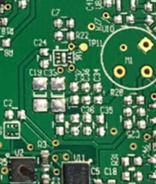
2AQ34-TDUS-05-04
May 24, 2020Meshify Pipe Temperature Sensor
Equipment Class
DSS - Part 15 Spread Spectrum Transmitter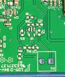
2AQ34-MDUS-05-04
May 24, 2020Meshify Ambient Temperature Sensor
Equipment Class
DTS - Digital Transmission System