2AQ5RNFCPN7150NFC Module
Shenzhen KTC Commercial Display Technology CO.,LTD.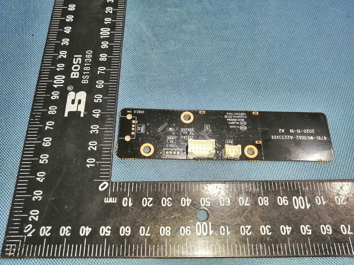
Click to zoom
Application Details
- Equipment Class
- DXX - Part 15 Low Power Communication Device Transmitter
- Date of Grant
- Apr 25, 2021
- Application Purpose
- Original Equipment
- Date of Application
- Apr 25, 2021
- Equipment Note
- NFC Module
- Frequency Range
- 13.56000000 - 13.56000000
- Country
- China
Documents & Files
Document Text
Text extracted from the exhibit documents filed with the FCC. Open a document above to read the original.
Users Manual
Shenzhen KTC Commercial Display Technology CO.,LTD. NFC Module Model Number: PN7150 Product Descrition: Best plug ́n play and high-performance full NFC solution PN7150 is a full NFC controller solution with integrated firmware and NCI interface designed for contactless communication at 13.56 MHz. It is compatible with NFC forum requirements.PN7150 is designed based on learnings from previous NXP NFC device generation. Product specification Frequency Band: 13.110 MHz to 14.010 MHz Nominal Operating Frequency: 13.56 MHz Work in Modes: Card Emulation Reader/Writer Peer-to-Peer NFC Type: NFC A Type NFC B Type NFC F Type NFC V Type Max. Data Rates: 848 Kbps Type of Modulation: ASK Number of Channels: 1 Antenna Type: Integral Antenna Maximum Field Strength: 61.07 dBμV/m at 3 meter Normal Test Voltage: 3.3 Vdc Extreme Test Voltage: 3.0 Vdc to 3.6 Vdc Extreme Test Temperature: -30 °C to +85 °C FCC Statement: This device complies with part 15 of the FCC rules. Operation is subject to the following two conditio ns: (1) this device may not cause harmful interference (2) this device must accept any interference received, including interference that may cause undesired operation. Changes or modifications not expressly approved by the party responsible for compliance could void the user’s authority to operate the equipment. NOTE: This equipment has been tested and found to comply with the limits for a Class B digital device, pursuant to part 15 of the FCC Rules. These limits are designed to provide reasonable protection against harmful interference in a residential installation. Shenzhen KTC Commercial Display Technology CO.,LTD. This equipment generates, uses and can radiate radio frequency energy and, if not installed and used in accordance with the instructions, may cause harmful interference to radio communications. However, there is no guarantee that interference will not occur in a particular installation. If this equipment does cause harmful interference to radio or television reception, which can be determined by turning the equipment off and on, the user is encouraged to try to correct the interference by one or more of the following measures: —Reorient or relocate the receiving antenna. —Increase the separation between the equipment and receiver. —Connect the equipment into an outlet on a circuit different from that to which the receiver is connected. —Consult the dealer or an experienced radio/TV technician for help. Important Note: In the event that these conditions cannot be met (for example certain laptop configurations or co- location with another transmitter), then the FCC authorization is no longer considered valid and the FCC ID cannot be used on the final product. In these circumstances, the OEM integrator will be responsible for re-evaluating the end product (including the transmitter) and obtaining a separate FCC authorization. Any company of the host device which install this modular with limit modular approval should perform the test of radiated emission and spurious emission according to FCC part 15C:15.225 and requirement.There is requirement that the grantee provide guidance to the host manufacturer for compliance with Part 15B requirements. Only if the test result comply with FCC part 15.225 and 15.209 requirement, then the host can be sold legally. Trace antenna designs: Not applicable. Antennas: Antenna type Antenna gain Integral Antenna Max gain: 0dBi End Product Labling: If the FCC identification number is not visible when the module is installed insideanother device, then the outside of the device into which the module is installed must also display a label referring to the enclosed module. This exterior label can use wording such as the following:Contains Transmitter Module FCC ID: 2AQ5RNFCPN7150. Information on test modes and additional testing requirements Any final host product with the modular transmitter installed should be under test according to guidance given in KDB 996369 D04. Individual modules enter test mode by burning firmware to the module,When something wrong happens in configuring test modes for host product with module, host product manufacturer should coordinate with module manufacturer for technical support. It is recommended that some investigative measurements should be taken to confirm that host product with module installed does not exceed the spurious emissions limits. Shenzhen KTC Commercial Display Technology CO.,LTD. Manual Information to the End User The OEM integrator has to be aware not to provide information to the end user regarding how to install or remove this RF module in the user’s manual of the end product which integrates this module. The end user manual shall include all required regulatory information/warning as show in this manual. When the module is installed inside another device, the user manual of this device must contain below warning statements; 1. This device complies with Part 15 of the FCC Rules. Operation is subject to the following two conditions: (1) This device may not cause harmful interference. (2) This device must accept any interference received, including interference that may cause undesired operation. 2. Changes or modifications not expressly approved by the party responsible for compliance could void the user's authority to operate the equipment. The devices must be installed and used in strict accordance with the manufacturer's instructions as described in the user documentation that comes with the product. Antenna type Antenna gain Integral Antenna Max gain: 0dBi The module must be installed in TV set and TV monitor have shielding. ISED Statement: - This device contains licence-exempt transmitter(s)/receiver(s) that comply with Innovation, Science and Economic Development Canada’s licence-exempt RSS(s). Operation is subject to the following two conditions: 1. This device may not cause interference. 2. This device must accept any interference, including interference that may cause undesired operation of the…
Text truncated - open the document above for the full version.
Cover Letter(s)
Shenzhen KTC Commercial Display Technology CO.,LTD. FCC ID: 2AQ5RNFCPN7150 To the certification reviewer: We are hereby applying for [Shenzhen KTC Commercial Display Technology CO.,LTD.] modular approval of the above-referenced FCC ID, based on compliance with all of the criteria as detailed below. Sincerely, [signature] [Hongbo Tang] [Certification Engineer] Part 15 Unlicensed Single Modular Transmitter Approval Justification per 15.212 Requirement per 15.212reference (i)The radio elements of the modular transmitter does not have their own RF shielding. (ii)The modular transmitter must have buffered modulation/data inputs (if such inputs are provided. All modulation and data inputs are buffered by circuitry on the transmitter chip. (iii)The modular transmitter must have its own power supply regulation. RF voltage regulation is handled on the module. (iv)The modular transmitter must comply with the antenna and transmission system requirements of §§ 15.203, 15.204(b) and 15.204(c). The modular with permanently antenna. (v)The modular transmitter must be tested in a stand-alone configuration, i.e., the module must not be inside another device during testing for compliance with Part 15 parameters. The modular transmitter must be tested in a stand-alone configuration, the module must not be inside another device during testing for compliance with part 15 requirements (vi)The modular transmitter must be equipped with either a permanently affixed label or must be capable of electronically displaying its FCC identification number. If the FCC ID is not visible when the module is installed inside another device, then the outside of the device into which the module is installed must also display a label referring to the enclosed module. A sample of the host label is provided as an exhibit, showing the FCC identifier of the module. the modular transmitter must have its own power supply and modular transmitter does not have its own RF shielding (vii)The modular transmitter must comply with any specific rules or operating requirements that ordinarily apply to a complete transmitter and the manufacturer must provide adequate instructions along with the module to explain any such requirements. A copy of these instructions must be included in the application for equipment authorization. The module complies fully with the operating requirements of Part 15 section C as demonstrated in the test report exhibit. (viii)The modular transmitter must comply with any applicable RF exposure requirements in its final configuration. FCC Rules in Sections 2.1091, 2.1093 and specific Sections of Part 15, RF Exposure to demonstrate compliance.
External Photos
Page 1 of 1 FCC ID: 2AQ5RNFCPN7150 IC:24301-NFCPN7150 Shenzhen UnionTrust Quality and Technology Co., Ltd. Address: Unit D/E of 9/F and 16/F, Block A, Building 6, Baoneng Science and Technology Park, Longhua District, Shenzhen, China Tel: +86-755-28230888 Fax: +86-755-28230886 E-mail: [email protected] Http://www.uttlab.com APPENDIX 2 PHOTOS OF EUT CONSTRUCTIONAL DETAILS EUT Photo EUT Photo ant
ID Label/Location Info
18.00mm 35.0mm PN7150 FCC ID:2AQ5RNFCPN7150 IC:24301-NFCPN7150 Label Location
Internal Photos
Page 1 of 1 FCC ID: 2AQ5RNFCPN7150 IC:24301-NFCPN7150 Shenzhen UnionTrust Quality and Technology Co., Ltd. Address: Unit D/E of 9/F and 16/F, Block A, Building 6, Baoneng Science and Technology Park, Longhua District, Shenzhen, China Tel: +86-755-28230888 Fax: +86-755-28230886 E-mail: [email protected] Http://www.uttlab.com APPENDIX 2 PHOTOS OF EUT CONSTRUCTIONAL DETAILS EUT Photo EUT Photo ant
RF Exposure Info
RF Exposure Requirements Product Description: NFC Module Model No.: PN7150 FCC ID: 2AQ5RNFCPN7150 IC: 24301-NFCPN7150 According to the KDB 447498 D01 V06, clause 4.3, the following RF exposure evaluation shall to demonstrate RF exposure compliance. 13.56 MHz Tx frequency: 13.56 MHz Type of Modulation: ASK Antenna Type: Integral antenna (Gain: 0 dBi) Nominal rated field strength: 61.07 dBμV/m at 3m Maximum allowed field strength of production tolerance: +/- 3dB Based on the Maximum allowed field strength of production tolerance was 64.07dBμV/m at 3m in frequency 13.56MHz, thus; The EIRP = [(FS*D) ^2*1000 / 30] = 0.0077 mW Thus; Conducted power = Radiated Power (EIRP) – Antenna Gain So; Conducted Power = 0.0077 mW. The SAR Exclusion Threshold Level for 13.56MHz when the minimum test separation distance is < 50mm: = [474 * (1 + log100/f(MHz))]/2 = 443mW Since the source-based time-averaging conducted output power is well below the SAR low threshold level, so the EUT is considered to comply with SAR requirement without testing. According to the RSS-102 Issue 5, the following RF exposure evaluation shall to demonstrate RF exposure compliance. Conducted Power = 0.0077 mW. The SAR Exclusion Threshold Level for 13.56MHz when the minimum test separation distance is < 50mm: Since the source-based time-averaging conducted output power is well below the SAR low threshold level, so the EUT is considered to comply with SAR requirement without testing.
Test Report
Page 2 of 27 Report No.: 210205008RFC-1 Shenzhen UnionTrust Quality and Technology Co., Ltd. Address: Unit D/E of 9/F and 16/F, Block A, Building 6, Baoneng science and technology park, Longhua district, Shenzhen, China Tel: +86-755-28230888 Fax: +86-755-28230886 E-mail: [email protected] http://www.uttlab.com UTTR-RF-RSS210-V1.1 Version Version No. Date Description V1.0 March 25, 2021 Original Page 3 of 27 Report No.: 210205008RFC-1 Shenzhen UnionTrust Quality and Technology Co., Ltd. Address: Unit D/E of 9/F and 16/F, Block A, Building 6, Baoneng science and technology park, Longhua district, Shenzhen, China Tel: +86-755-28230888 Fax: +86-755-28230886 E-mail: [email protected] http://www.uttlab.com UTTR-RF-RSS210-V1.1 CONTENTS 1. GENERAL INFORMATION ....................................................................................................................................... 4 1.1 CLIENT INFORMATION ........................................................................................................................................ 4 1.2 EUT INFORMATION ............................................................................................................................................ 4 1.2.1 GENERAL DESCRIPTION OF EUT ............................................................................................................ 4 1.2.2 DESCRIPTION OF ACCESSORIES .............................................................................................................. 4 1.3 PRODUCT SPECIFICATION SUBJECTIVE TO THIS STANDARD ................................................................................. 4 1.4 OTHER INFORMATION ......................................................................................................................................... 5 1.5 DESCRIPTION OF SUPPORT UNITS ...................................................................................................................... 5 1.6 TEST LOCATION ................................................................................................................................................. 5 1.7 TEST FACILITY ................................................................................................................................................... 5 1.8 DEVIATION FROM STANDARDS ............................................................................................................................ 5 1.9 ABNORMALITIES FROM STANDARD CONDITIONS .................................................................................................. 5 1.10 OTHER INFORMATION REQUESTED BY THE CUSTOMER ........................................................................................ 6 1.11 MEASUREMENT UNCERTAINTY ........................................................................................................................... 6 2. TEST SUMMARY ...................................................................................................................................................... 7 3. EQUIPMENT LIST .................................................................................................................................................... 8 4. TEST CONFIGURATION .......................................................................................................................................... 9 4.1 ENVIRONMENTAL CONDITIONS FOR TESTING ........................................................................................................ 9 4.1.1 NORMAL OR EXTREME TEST CONDITIONS ............................................................................................... 9 4.1.2 RECORD OF NORMAL ENVIRONMENT....................................................................................................... 9 4.2 TEST CHANNELS ............................................................................................................................................... 9 4.3 EUT TEST STATUS ............................................................................................................................................ 9 4.4 PRE-SCAN .................................................................................................................................................... 10 4.4.1 PRE-SCAN UNDER ALL DATA RATES ........................................................................................................ 10 4.4.2 USED FOR TESTING OF WORST-CASE DATA RATES .................................................................................. 10 4.5 TEST SETUP .................................................................................................................................................... 11 4.5.1 FOR RADIATED EMISSIONS TEST SETUP ................................................................................................ 11 4.5.2 FOR CONDUCTED EMISSIONS TEST SETUP ............................................................................................ 12 4.5.3 FOR CONDUCTED RF TEST SETUP ........................................................................................................ 12 4.6 SYSTEM TEST CONFIGURATION ........................................................................................................................ 13 5. RADIO TECHNICAL REQUIREMENTS SPECIFICATION .................................................................................... 14 5.1 REFERENCE DOCUMENTS FOR TESTING ............................................................................................................ 14 5.2 ANTENNA REQUIREMENT ................................................................................................................................. 14 5.3 99% & 20DB BANDWIDTH ............................................................................................................................... 14 5.4 THE FIELD STRENGTH OF ANY EMISSIONS APPEARING OUTSIDE OF THE 13.110-14…
Text truncated - open the document above for the full version.
Test Setup Photos
Page 1 of 2 FCC ID: 2AQ5RNFCPN7150 IC: 24301-NFCPN7150 Shenzhen UnionTrust Quality and Technology Co., Ltd. Address: Unit D/E of 9/F and 16/F, Block A, Building 6, Baoneng Science and Technology Park, Longhua District, Shenzhen, China Tel: +86-755-28230888 Fax: +86-755-28230886 E-mail: [email protected] Http://www.uttlab.com APPENDIX 1 PHOTOS OF TEST SETUP Radiated emission Test Setup (9KHz~30MHz) Radiated emission Test Setup (30 MHz~1 GHz) Page 2 of 2 FCC ID: 2AQ5RNFCPN7150 IC: 24301-NFCPN7150 Shenzhen UnionTrust Quality and Technology Co., Ltd. Address: Unit D/E of 9/F and 16/F, Block A, Building 6, Baoneng Science and Technology Park, Longhua District, Shenzhen, China Tel: +86-755-28230888 Fax: +86-755-28230886 E-mail: [email protected] Http://www.uttlab.com Conducted Emissio Test Setup
Contact Information
Applicant
Liu Huan(Certification Director)
Technical Contact
Shenzhen UnionTrust Quality and Technology Co., LtBilly Li
[email protected](86-755) 2823 0888
Unit D/E of 9/F and 16/F, Block A, Building 6, Bao · Shenzhen · China
Non-Technical Contact
Shenzhen UnionTrust Quality and Technology Co., LtBilly Li
[email protected](86-755) 2823 0888
Test Firm
Shenzhen UnionTrust Quality and Technology Co., LtGeorge Luo
[email protected]+86-755-28230888
Technical Specifications
| # | Rule Parts | Frequency Range | Power Output |
|---|---|---|---|
| 1 | 15C | 13.56 MHz - 13.56 MHz | - |
Other Applications from Shenzhen KTC Commercial Display Technology CO.,LTD.
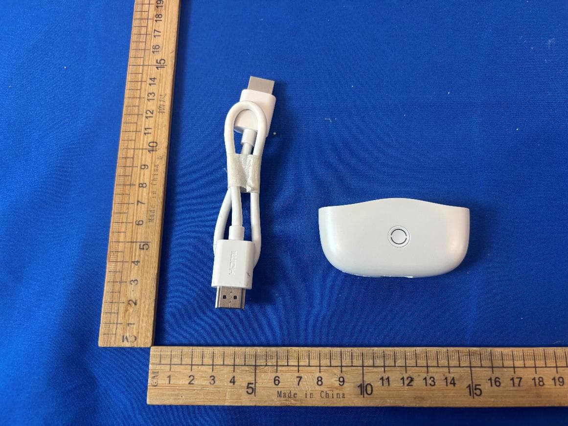
2AQ5R-HGP1RX
Aug 10, 2026Wireless Display Adapter
Equipment Class
NII - Unlicensed National Information Infrastructure TX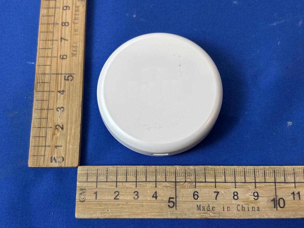
2AQ5R-HG-D2
Aug 05, 2026Wireless Display Adapter
Equipment Class
NII - Unlicensed National Information Infrastructure TX2AQ5R-HM-6P
Mar 30, 2026Speakerphone
Equipment Class
DSS - Part 15 Spread Spectrum Transmitter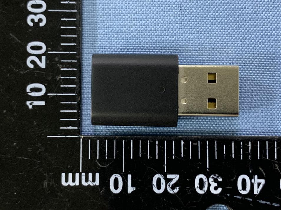
2AQ5R-UB01
Sep 28, 2024Dongle
Equipment Class
DTS - Digital Transmission System
2AQ5R-UD10
Sep 28, 2024Dongle
Equipment Class
DSS - Part 15 Spread Spectrum Transmitter