2AQ69SENTIMATEMulti sensor and multi wireless Product Accelerator for IoT
FAE TECHNOLOGY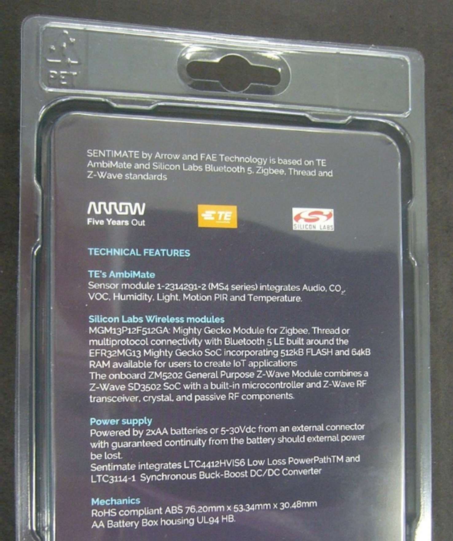
Click to zoom
Application Details
- Equipment Class
- DXX - Part 15 Low Power Communication Device Transmitter
- Date of Grant
- Feb 06, 2020
- Application Purpose
- Original Equipment
- Date of Application
- Feb 04, 2020
- Equipment Note
- Multi sensor and multi wireless Product Accelerator for IoT
- Frequency Range
- 908.40000000 - 916.00000000
- Company
- FAE TECHNOLOGY
- Country
- Italy
Documents & Files
Document Text
Text extracted from the exhibit documents filed with the FCC. Open a document above to read the original.
Users Manual
SENTIMATE Multi sensor and multi wireless Product Accelerator for IoT DATA SHEET | SENTIMATE Summary 1. INTRODUCTION 3 2. SENTIMATE IMAGES 4 3. DESCRIPTION AND BLOCK DIAGRAM 5 4. HARDWARE & COMPONENTS DETAIL 6 4.1. AmbiMate sensor module 6 4.1.1. Temperature Sensor: 6 4.1.2. Relative Humidity Sensor: 7 4.1.3. Ambient Light Photo Sensor: 7 4.1.4. Passive Infrared Motion Sensor (PIR): 7 4.1.5. Acoustic Microphone with Pre-Amp 7 4.1.6. Equivalent CO2 / VOC Gas Sensor 8 4.1.7. AmbiMate connection to MCUs 9 4.2. MGM13P 2.4GHz wireless module 10 4.3. ZGM130S Z-Wave module 12 4.4. Power supply 14 4.4.1. Battery input path 14 4.4.2. External DC input path 16 4.4.1. Power Path 16 5. SENTIMATE CONNECTOR, LED and PUSH BUTTON 18 6. RF ELECTRICAL SPECIFICATIONS 19 7. EU REGOLATORY DISCLOSURES 26 8. FCC COMPLIANCE STATEMENT (USA) 26 9. OPERATING ENVIRONMENT 26 10. DISCLAIMERS 26 DATA SHEET | SENTIMATE 1. INTRODUCTION This data sheet provides the description of the SENTIMATE product accelerator for IoT. SENIMATE is a complete electronics board and plastic housing system that includes short range wireless communication capabilities and multi sensor technology, powered by external DC supply or from a couple of AA non rechargeable bat- teries. As product accelerator, SENTIMATE can be used from makers, developers, professional engineers and from all who want the benefit of an off the shelf industrialized system and doesn’t have time and/or money to invest in a custom solution. For details about Product Accelerators, please visit: www.fae.technology https://fae.technology/product-accelerator-program/ DATA SHEET | SENTIMATE 2. SENTIMATE IMAGES DATA SHEET | SENTIMATE 3. DESCRIPTION AND BLOCK DIAGRAM Based on TE AmbiMate sensor, Bluetooth 5, Zigbee, Thread and Z-Wave from Silicon Labs, its construction and market certifications, its embedded power path and battery or 5-40V input power makes SENTIMATE ideal for test and Proof of Concept in the field. Ready to go Electronics, plastics and accessories present in the kit and ready to use in the market for PoC. Silicon Labs Simplicity Studio Easy firmware development with the free of charge programming tool from Silicon Labs with examples and drivers specifics for SENTIMATE. Smart home device oriented SENTIMATE is the perfect product accelerator for the smart home applications in which environmental sensors and multi radio protocols are embedded to help any developer to develop applications with several standards. Multisensor solution AmbiMate sensor module from TE embeds temperature, humidity, VOC, eCO2, microphone and PIR motion for a com- plete environmental analysis. Below is the block diagram of the SENTIMATE. DATA SHEET | SENTIMATE 4. HARDWARE & COMPONENTS DETAIL 4.1. AmbiMate sensor module TE Connectivity (TE)’s AmbiMate sensor module MS4 series provides an application specific set of sensors on a ready to attach PCB assembly for easy integration into a host product. Design resources are freed and time to market accel- erated by integrating the MS4 series pre-engineered, four core sensor solution for Motion / Light / Temperature / Hu- midity into your next product. The MS4 series sensor modules embedded in the SENTIMATE includes VOC (Volatile Organic Compound), eCO2 (equivalent carbon dioxide) and sound detection. Add the capability to monitor air quality through the capture of VOC concentrations. The MS4 series with a microphone can be used to augment motion detec- tion or to listen for sound events. All MS4 series sensor modules offer the flexibility of sharing a common seven posi- tion connection. 4.1.1. Temperature Sensor: The temperature sensor is combined with the relative humidity sensor in the same package. The sensor’s I 2C output is read by the AmbiMate’s microcontroller. Note: Actual performance may vary due to customer enclosure design. Enclo- sure should allow for air circulation to ensure sensor is responding to temperature changes within the intended envi- ronment of use. Please refer to 108- 133092 for performance of product. 3.4.2 DATA SHEET | SENTIMATE 4.1.2. Relative Humidity Sensor: The relative humidity sensor is combined with the temperature sensor in the same package. The sensor’s I 2C output is read by the AmbiMate’s microcontroller. Note: Actual performance may vary due to customer enclosure design. Enclo- sure should allow for air circulation to ensure sensor is responding to humidity changes within the intended environ- ment of use. Please refer to 108-133092 for performance of product. 3.4.3 4.1.3. Ambient Light Photo Sensor: The photo sensor mimics the responsivity of the human eye. The analog output from the sensor is read by the Ambi- Mate’s microcontroller’s analog to digital converter. Note: Ambient light impinges directly on the sensor, no light pipe. If in the final application the photo sensor becomes shadowed, then a light pipe will be required to achieve optimum performance. The light pipe design is dependent upon the final application and use and is beyond the scope of this application specification. Please refer to 108-133092 for performance of product. 4.1.4. Passive Infrared Motion Sensor (PIR): The PIR senses motion. The output from the sensor is read by the AmbiMate’s microcontroller. During design-in and mounting the AmbiMate consideration should be given for placement of the device on a ceiling, wall or in a corner to maximize the PIR sensors effectiveness. A Fresnel lens is required, please contact TE customer support for information on the lens. During a motion event, the Event_Out pin will go high. Related to the PIR sensor is the motion event LED. When the AmbiMate senses motion the motion event LED will illuminate. For enhanced motion detection, please con- tact TE customer support 4.1.5. Acoustic Microphone with Pre-Amp The microphone is omnidirectional with an analog output. The analog output from the microphone is read by the Am- biMate’s microcontroller’s analog to digital converter and is available to t…
Text truncated - open the document above for the full version.
Block Diagram
5 5 4 4 3 3 2 2 1 1 DD CC BB AA POWER PATH +3V3_ON +VBATT BATTERY 2xAA Alkaline +VCONN 5V-40V DC MGM MCU ZIGBEE BLE THREAD H-F Oscillator: 38.4MHz L-F Oscillator: 32.768 kHz Z-WAVE SIP MCU H-F Oscillator: 39MHz RGB PUSH BUTTON PWM WAKE IO I2C AMBIMATE 1Gb FLASH SPI WAKE IO AUDIO PROTECTION & FILTER PROTECTION & FILTER BUCK BOOST +3V3_CONN +3V3_BATT +3V3_AMBI UART +3V3_ZWAVE GPIO GPIO POWER SWITCH POWER SWITCH LEVEL TRANSLATOR I2C LEVEL TRANSLATOR I2C GPIO I2C POWER SWITCH GPIO+3V3_MGM WAKE IO PWM WAKE IO AUDIO Project Code Rev. changes Rev. Sheet / Board Approved Customer Project Code Page name Data Il presente progetto è tutelato dalla legge sul diritto d'autore, che vieta a terzi la riproduzione e l'utilizzo anche parziale senza il consenso di FAE Technology S.p.A. Designer Internal Code Thursday, October 17, 2019 ARROW Christian RaineriMartin Cossali - 01 - BLOCK DIAGRAMSENTIMATE SENTIMATE 52 See Revision Page Mail: [email protected] via C. Battisti 136, 24025, Gazzaniga (Bg), Italy Tel: +39 035738130 2019-0001 4 - Project Code Rev. changes Rev. Sheet / Board Approved Customer Project Code Page name Data Il presente progetto è tutelato dalla legge sul diritto d'autore, che vieta a terzi la riproduzione e l'utilizzo anche parziale senza il consenso di FAE Technology S.p.A. Designer Internal Code Thursday, October 17, 2019 ARROW Christian RaineriMartin Cossali - 01 - BLOCK DIAGRAMSENTIMATE SENTIMATE 52 See Revision Page Mail: [email protected] via C. Battisti 136, 24025, Gazzaniga (Bg), Italy Tel: +39 035738130 2019-0001 4 - Project Code Rev. changes Rev. Sheet / Board Approved Customer Project Code Page name Data Il presente progetto è tutelato dalla legge sul diritto d'autore, che vieta a terzi la riproduzione e l'utilizzo anche parziale senza il consenso di FAE Technology S.p.A. Designer Internal Code Thursday, October 17, 2019 ARROW Christian RaineriMartin Cossali - 01 - BLOCK DIAGRAMSENTIMATE SENTIMATE 52 See Revision Page Mail: [email protected] via C. Battisti 136, 24025, Gazzaniga (Bg), Italy Tel: +39 035738130 2019-0001 4 -
External Photos
EXTERNAL PHOTOS Top side Bottom side Labeling Packaging FRONT BOTTOM INTERNAL
ID Label/Location Info
FAE Technology s.p.a. Via C. Battisti, 136 Gazzaniga (BG) - Italia Model: Sentimate S/N: SEN000001 FCC ID: 2AQ69SENTIMATE CONTAINS FCC ID: QOQMGM13P
Internal Photos
INTERNAL PHOTOS TOP BOTTOM CLOSE UP OF MGM13P CERTIFIED MODULE
Operational Description
1 SENTIMATE board: getting started and FW examples 2 Document Revision REVISION DATE AUTHOR DESCRIPRION 1 10/06/2019 Ing. M.Gualdi First draft based on schematic V3 2 27/06/2019 Ing. M.Gualdi Added chapter 2 3 09/07/2019 Ing. L. Moioli English version 4 23/07/2019 Ing. L. Moioli Added example 13 5 29/07/2019 Ing. M.Gualdi Updated board images 6 13/12/2019 Ing. E.Limonta Added information on the antenna 3 Index 1. SYSTEM CONFIGURATION 4 AmbiMate multi-sensor module 2314291-2 (TE) 4 Radio module ZGM130S037HGN1 (Silicon Labs) 4 Radio module MGM13P12F512GA (Silicon Labs) 4 RGB LED 4 Antenna 4 .2 DEVELOPMENT ENVIRONMENT SETUP 6 Sentimate Board Setup 6 Power supply Setup 6 Debugger Setup 7 IDE Setup 8 Sentimate Examples 9 How to import the examples 11 Examples List 14 MGM13P12F512GA Module examples 15 ZGM130S Module examples 20 4 1. SYSTEM CONFIGURATION SENTIMATE board is equipped with the following macro elements: AmbiMate multi-sensor module 2314291-2 (TE) At the following link you can find the description of the module developed by TE. Radio module ZGM130S037HGN1 (Silicon Labs) At the following link you can find the description of the module developed by Silicon Labs. - Transmit frequencies: 908.4 MHz - 916.0 MHz - Maximum TX power 4 dBm Radio module MGM13P12F512GA (Silicon Labs) At the following link you can find the description of the module developed by Silicon Labs. - Transmit frequencies: 2400 MHz – 2483.5 MHz - Maximum TX power 19 dBm RGB LED At the following link you can find the description of the LED. Antenna At the following link you can find the description of the antenna . - Transmit frequencies: 908.4 MHz - 916.0 MHz - Peak gain: 1.4 dBi - The ZGM130S and MGM13P modules can transmit simultaneously 5 6 .2 DEVELOPMENT ENVIRONMENT SETUP In order to use the examples, the following tools are required: SENTIMATE Board Power supply access Segger J-Link (any version) or compatible and JTAG 10-Pole cable Simplicity Studio V4 Sentimate Board Setup In order to program the SENTIMATE board, two JTAG connectors compliant with 10-pole standard are available. The first one is dedicated to programming the M13P12F512GA module, while the second one is dedicated to programming the ZGM130S module. To access these connectors, it is necessary to remove the upper cover of the board. Below is a picture of the board with the two JTAG connectors highlighted in red. Power supply Setup The board can be powered in two different ways: External DC power supply (from 5 to 40Vdc on external 2 poles connector) Power supply through two AA alkaline type batteries During development phase, it is recommended to use external power supply, to avoid limitation due to battery duration. For example, you can use a power adapter with standard output of 5V, 12V, 19V o 24V, or you can use a power supply with adjustable voltage. The electric current required by the board depends on the provided supply voltage, in the worst case of 5V supply, it is necessary to provide a maximum current of 500 [mA]. In order to work properly, the board requires that supply jumpers are closed or that instead of a jumper, an ammeter is inserted to monitor power consumption. The following picture shows two closed jumpers that provide power supply to the AMBIMATE and MGM13P12F512GA modules, while ZGM130S module is not enabled. 7 Debugger Setup It is recommended to use the J-Link debugger with the latest software version installed, downloadable at this link. It is recommended to use the software package starting from version V6.46g, in which both devices MGM13P12F512GA and ZGM130S are fully supported. If you are in possession of a Silicon Labs wireless development kit, it is possible to use BRD4001A boards configured for debugging external devices. Below is a picture that shows the connection between the J-Link and the board through one of the JTAG ports. 8 IDE Setup The development environment used is Simplicity Studio V4, provided by Silicon Labs and downloadable from this link. Once you have downloaded the installation file suited for your platform, start it and follow the installation wizard. Silicon Labs provides AN0822 document on how to use the development environment. Once the installation phase is completed, you have to install the SDK libraries related to the radio modules mounted on the SENTIMATE board. To do this, start Simplicity Studio and once the IDE has loaded, use the “Installation manager” tool to select the additional components to install. In this screen select “Install by Product Group” and go to the next screen. 9 Here, select the needed radio components and complete the installation. Important Note: in order to download and access all the functionalities of the Zigbee and Z- Wave libraries it is necessary to register a Silicon Labs development kit. Sentimate Examples The first thing to do is downloading the archive containing the examples from the ARROW site and unzip it in any position on the disk. Folders structure Example folders are organized as in the following picture: BSP Inside this folder, there are the drivers to manage the hardware components mounted on the board. .2.5.2.1 Ambimate These drivers are dedicated to interfacing with the AMBIMATE module. .2.5.2.2 SENTIMATE These drivers help interfacing the microcontroller with the remaining peripherals available on the board. 10 NOTE: These drivers were developed for the MGM13P12F512GA radio module, but are easily adapted for the ZGM130S module as well. MGM13P12F512GA Inside this folder there are the various examples to use with the MGM13P12F512GA module. In table 1, of chapter 4, it is reported the example list with a brief description concerning the components involved in each example. ZGM130S Inside this folder there are the various examples to use with the ZGM130S module. 11 In table 2, of chapter 4, it is reported the example list with a brief description concerning the components involved in each example. How to import the examples To import the exam…
Text truncated - open the document above for the full version.
Test Report
The results of tests and checks reported in this Test Report refer exclusively to the samples tested and described in the Report itself. This Report shall not be reproduced partially the written approval of IMQ S.p.A.. The authenticity of this Test Report and its contents can be verified by contacting IMQ S.p.A., responsible for this Test Report. TEST REPORT No. AR19-0042423-01 performed in accordance with FCC Rules: Code of Federal Regulations (CFR) no. 47 Part 15 Subpart C Section 15.249 PRODUCT IoT device for environmental monitoring with Z-Wave wireless communication MODEL(s) TESTED SENTIMATE FCC ID 2AQ69SENTIMATE TRADE MARK(s) FAE TECHNOLOGY APPLICANT FAE TECHNOLOGY S.p.A. ∼ Via C. Battisti, 136 ∼ I-24025 Gazzaniga (BG) Tested by Robertino Torri [Laboratory technician] Approved by Giovanni Di Turi [Laboratory manager] Revision Sheet Release No. Date Revision Description Rev. 0 2019-09-25 First edition Digital signed - AR19-0042423-01_TR_FCC 15.249 - FAE TECHNOLOGY - SENTIMATE M od. TRF 3713 / 2 B.U. P ROD UCTS C ONFORMITY A SSESSMENT - R ADIO E QUIPMENT L ABORATORY Test Report No. AR19-0042423-01 Date: 2019-09-25 Page 2 of 25 Mod. TRF 3 713 / 2 B.U. P RODUCTS C ONFORMITY A SSESSMENT - R ADIO E QUIPMENT L ABORATORY 1. GENERAL DATA SAMPLE Samples received on 2019-09-03 (Item(s) sampled and sent by applicant) IMQ reference samples BEM 96822 Samples tested No. 1 Object under analysis recognition Not carried out Except where stated, characteristics of products were taken from client description and were not verified by the laboratory Date of acceptance of test item 2019-09-03 TEST LOCATION Testing dates 2019-09-05 ÷ 2019-09-25 Testing laboratory. IMQ S.p.A. - Via Quintiliano, 43 – I-20138 Milano Testing site Via Quintiliano, 43 – I-20138 Milano ENVIRONMENTAL CONDITIONING Parameter Measured Ambient Temperature 21.4 °C ÷ 23,8 Relative Humidity 53 % ÷ 59% Atmospheric Pressure 940 ÷ 1005 mbar The laboratory is monitored by a continuous environmental conditions measurements system. Temperature, humidity and pressure data are recorded on a weekly basis and stored in local archive. REMARKS Throughout this report a point is used as the decimal separator. The ability or reliability of this product to perform its intended function in a particular application has not been investigated. Unless otherwise specified, warnings, installation instruction and/or user manual provided with the sample have been checked in Italian or English version only. IMQ declines any responsibility derived from missing or wrong information provided aside by the applicant. Test Report No. AR19-0042423-01 Date: 2019-09-25 Page 3 of 25 Mod. TRF 3 713 / 2 B.U. P RODUCTS C ONFORMITY A SSESSMENT - R ADIO E QUIPMENT L ABORATORY 2. REFERENCE DOCUMENT DOCUMENT DATE TITLE 47 CFR Part 15 2015 Radio Frequency Device ANSI C63.4 2014 American National Standard for Methods of Measurement of Radio-Noise Emissions from Low-Voltage Electrical and Electronic Equipment in the Range of 9 kHz to 40 GHz ANSI C63.10 2013 American National Standard of Procedures for Compliance Testing of Unlicensed Wireless Devices Test Report No. AR19-0042423-01 Date: 2019-09-25 Page 4 of 25 Mod. TRF 3 713 / 2 B.U. P RODUCTS C ONFORMITY A SSESSMENT - R ADIO E QUIPMENT L ABORATORY 3. EQUIPMENT UNDER TEST (EUT) DETAILS GENERAL DATA (according to manufacturer declaration) MODEL (basic) Description SENTIMATE Z-wave radio module integrate in IoT device with wireless communication functions VARIANTS (derived) Description / / FCC ID 2AQ69SENTIMATE Manufacturer FAE TECHNOLOGY S.p.A. – Via C. Battisti, 136 – IT-24025 Gazzaniga BG Equipment classification According to the definition 15.3 (o) EUT is a Intentional Radiator operating within the bands 902 ÷ 928 MHz so it shall fulfill provisions of 47CFR Part 15 Subpart C – Intentional radiators – and Section 15.249 Type of equipment DTS - Digital transmission equipment Operating frequency 908.4 MHz ; 908.42 MHz; 916 MHz Field strength peak 90.96 dBμV/m @3m Modulation GFSK Channel 3 channel (CH0: 916.00 MHz; CH1: 908.400MHz; CH2: 908.420MHz) Antenna Dedicated Remarks None Test Report No. AR19-0042423-01 Date: 2019-09-25 Page 5 of 25 Mod. TRF 3 713 / 2 B.U. P RODUCTS C ONFORMITY A SSESSMENT - R ADIO E QUIPMENT L ABORATORY 4. TEST CONFIGURATION OF UNIT UNDER TEST EUT PORTS Port Description Max length Enclosure Plastic AC power / / DC power Internal supply by 2 x 1.5 V size AA alkaline battery; External supply 5 to 40 V by external source. / Earth / / Telecommunication / / Signal & Control / / Antenna Dedicated / STATE OF THE EUT DURING TESTS Ref. Transmission Mode Description #1 CW Continuous unmodulated transmission mode (constant tone) #2 Modulated Continuous modulated transmission (duty cycle close to 100%) #3 Normal operating Receiving mode / Normal transmission SUPPORT EQUIPMENT Defined as equipment needed for correct operation or loading of the EUT, but not considered as tested: Equipment Manufacturer Model PC with serial terminal software for RF transmission management / / EUT Antenna Port AC Power Port Earth Port Telecommunication Port Signal/Control Port DC Power Port Enclosure Port Test Report No. AR19-0042423-01 Date: 2019-09-25 Page 6 of 25 Mod. TRF 3 713 / 2 B.U. P RODUCTS C ONFORMITY A SSESSMENT - R ADIO E QUIPMENT L ABORATORY ELECTROMAGNETICALLY RELEVANT COMPONENTS Component No. Manufacturer Model Z-wave module 1 SILICON LABS ZGM130S Main Board 1 FAE TECHNOLOGY 20190001_V3 RFI SUPPRESSION DEVICES Component No. Manufacturer Model / / / / EMI PROTECTION DEVICES Component No. Manufacturer Model / / / / EUT TECHNICAL DOCUMENTATION Document Reference / / Test Report No. AR19-0042423-01 Date: 2019-09-25 Page 7 of 25 Mod. TRF 3 713 / 2 B.U. P RODUCTS C ONFORMITY A SSESSMENT - R ADIO E QUIPMENT L ABORATORY 5. METHODS OF MEASUREMENT All compliance measurements have been carried out using the procedures described in the standard ANSI C63.4-2014 (excluding sub-par. 4.1.5.2, 5.7 9 and 14) and Section 15.31 of CFR47 Part 15 –…
Text truncated - open the document above for the full version.
Test Setup Photos
FCC ID: 2AQ69SENTIMATE FAE TECHNOLOGY – Model: SENTIMATE Radiated Measurements Test Set-up
Contact Information
Applicant
Christian Raineri
Technical Contact
FAE TECHNOLOGY S.P.A.Christian Raineri
[email protected]+39035738130
Via C.Battisti,136 · Gazzaniga BG · Italy
Test Firm
Istituto Italiano del Marchio di Qualita S.p.A.Matteo Raimondi
Technical Specifications
| # | Rule Parts | Frequency Range | Power Output |
|---|---|---|---|
| 1 | 15C | 908.4 MHz - 916 MHz | - |