2AQ6KA1004Pulsed Coherent Radar
Acconeer AB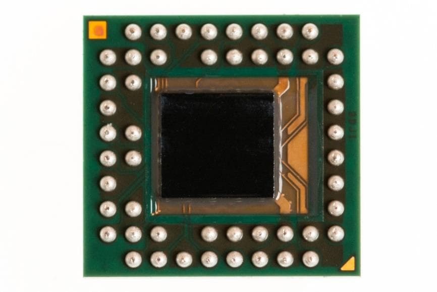
Click to zoom
Application Details
- Equipment Class
- FDS - Part 15 Field Disturbance Sensor
- Date of Grant
- Sep 04, 2023
- Application Purpose
- Original Equipment
- Date of Application
- Aug 20, 2023
- Equipment Note
- Pulsed Coherent Radar
- Frequency Range
- 57000.00000000 - 64000.00000000
- Company
- Acconeer AB
- Country
- Sweden
Documents & Files
Document Text
Text extracted from the exhibit documents filed with the FCC. Open a document above to read the original.
Users Manual
A111 – Pulsed Coherent Radar Operational description, User manual, and Installation instruction A111 Pulsed Coherent Radar (PCR) Operational description, User manual, and Installation instruction © 2023 Copyright by Acconeer 2023-07-22 Page 2 of 32 Features • Fully integrated sensor - 60 GHz Pulsed Coherent Radar (PCR) - Integrated Baseband, RF front-end and Antenna in Package (AiP) - 5.5 x 5.2 x 0.88 mm fcCSP, 0.5 mm pitch • Accurate distance ranging and movements - Measures absolute range up to 2 m (1) o Absolute accuracy in mm - Relative accuracy in μm - Possible to recognize movement and gestures for several objects - Support continuous and single sweep mode - HPBW typical of 65 (H-plane) and 53 degrees (E-plane) • Easy integration - One chip solution with integrated Baseband and RF - Can be integrated behind plastic or glass without any need for a physical aperture - Single reflowable component - 1.8 V single power supply, enable with Power on Reset (PoR) - Clock input for crystal 24 MHz - SPI interface for data transfer, up to 50 MHz SPI clock support - INTERRUPT support A111 Overview The A111 is a radar system based on pulsed coherent radar (PCR) technology and is setting a new benchmark for power consumption and distance accuracy – fully integrated in a small package of 29 mm 2 . The A111 60 GHz radar system is optimized for high precision and ultra-low power, delivered as a one package solution with integrated Baseband, RF front-end and Antenna in Package (AiP). This will enable easy integration into any portable battery driven device. The A111 is based on leading-edge patented sensor technology with pico-second time resolution, capable of measuring absolute distance with mm accuracy up to a range of 2 m (1) and with configurable update rate. The A111 60 GHz radar remains uncompromised by any natural source of interference, such as noise, dust, color and direct or indirect light. Applications • High precision distance measurements with mm accuracy and high update rate • Ultra-low power consumption, e.g. average power consumption 0.2 mW at 0.1 Hz update rate, 3 mW at 10 Hz update rate and 20 mW at 100 Hz update rate • Proximity detection with high accuracy and the possibility to define multiple proximity zones • Motion detection, Speed detection • Enables material detection • High precision object tracking, enabling gesture control • High precision tracking of 3D objects • Monitor vital life signs such as breathing and pulse rate (1) 2m ranging is guaranteed for an object size, shape and dielectric properties corresponding to a spherical corner reflector of 5 cm radius. A111 Pulsed Coherent Radar (PCR) Operational description, User manual, and Installation instruction Page 3 of 32 2023-07-22 © 2023 Copyright by Acconeer 1 Table of Contents 2 Revision History ............................................................................................................................ 4 3 Description ..................................................................................................................................... 5 3.1 Functional Block Diagram ................................................................................................... 6 4 Pin Configuration and Functions ................................................................................................ 7 5 Specifications ................................................................................................................................ 9 5.1 Absolute Maximum Ratings ................................................................................................ 9 5.2 Environmental Sensitivity .................................................................................................... 9 5.3 Recommended Operating Conditions ............................................................................. 10 5.4 Electrical Specification ....................................................................................................... 10 5.5 Power Consumption Summary ......................................................................................... 11 6 Timing Requirements ................................................................................................................. 13 6.1 Serial Peripheral Interface ................................................................................................. 13 7 Typical Characteristics ............................................................................................................... 15 7.1 Radar Loop Gain Pattern ................................................................................................... 15 7.2 Relative Phase Accuracy ................................................................................................... 16 8 Functional Description ............................................................................................................... 17 8.1 Acconeer Software ............................................................................................................. 18 8.2 Software Integration ........................................................................................................... 18 8.3 Power Sequences............................................................................................................... 19 9 Layout Recommendations ......................................................................................................... 22 9.1 XTAL ..................................................................................................................................... 23 9.2 Power Supply ...................................................................................................................... 24 10 Regulatory Approval ................................................................................................................... 26 10.1 ETSI .................................................................…
Text truncated - open the document above for the full version.
Attestation Statements
Date: 2 nd of Auguts 2023 Postal address Västra Varvsgatan 19 SE-211 77 Malmö Visiting address Västra Varvsgatan 19 SE-211 77 Malmö Telephone: +46 (0)10 218 92 00 E-mail [email protected] Website www.acconeer.com Federal Communication Commission Authorization and Evaluation Division 7435 Oakland Mills Road Columbia, MD 21046 USA 2023-08-02 Attestation Statement according to 2.911(d)(5)(i) and 2.911(d)(5)(ii) FCC ID: 2AQ6KA1004 TO WHOM IT MAY CONCERN: Hereby we certify that the equipment for which authorization is sought is not “covered” equipment prohibited from receiving an equipment authorization pursuant to section 2.903 of the FCC rules. Further we certify that, as of the date of the filing of the application, Acconeer AB is not identified on the Covered List as an entity producing “covered” equipment. Sincerely, Acconeer AB FRN: 0027831130 Mikael Egard +46 (0)10 218 92 00 [email protected]>
Cover Letter(s)
CONFIDENTIALITY REQUEST for Certification Service in USA Federal Communication Commission Equipment Authorization Division, Application Processing Branch 7435 Oakland Mills Road Columbia, MD 21048 <2023-07-22> TO WHOM IT MAY CONCERN Pursuant to Paragraphs §0.457 and 0.459 of the Commission’s Rules (47 C.F.R.) and Section §552(b) (4) of the Freedom of Information Act, we requests confidentiality for the following products: FCC ID Model name 2AQ6KA1004 A111 Module for SRD radar 60 GHz For the product stated above, we request that the following information be held confidential; Exhibits Long-Term Confidentiality Short-Term Confidentiality Short-Term Confidentiality Days External Photos Internal Photos Block Diagram Schematics Test Setup Photos User’s Manual Parts List Tune Up Operational Descriptions The long-term confidentiality exhibits contain our trade secrets and proprietary information that could be of benefit to our competitors. The short-term confidentiality on the basis of ensuring that business sensitive information remains confidential until the actual marketing of our new device. If you have any questions, please feel free to contact me at the address shown below. Sincerely, Name / Title: Mikael Egard / COO Company: Acconeer AB Adress: Västra Varvsgatan 19, 211 77 Malmö, Sweden Phone: +46 (0)10 218 92 00 E-Mail: [email protected]
Cover Letter(s)
Federal Communication Commission Equipment Authorization Division, Application Processing Branch 7435 Oakland Mills Road Columbia, MD 21048 Certification and Engineering Bureau Innovation, Science and Economic Development Canada Spectrum Engineering Branch 3701 Carling Avenue, Building 94 Ottawa, Ontario K2H 8S2 Subject: FCC / ISED Modular Approval Statement FCC ID: CN: (Company Number) UPN: (Unique Product Number) HVIN: (Hardware Version Id. Number) PMN: (Product Marketing Name) HMN: (Host Marketing Name) FVIN: ( Firmware Version Id . Number) TO WHOM IT MAY CONCERN Pursuant to Paragraphs RSP-100, Issue 12 and CFR § 15.212, we herewith declare for our module. Modular approval requirement Yes No * (a) The radio elements shall have the radio frequency circuitry shielded. Physical/discrete and tuning capacitors may be located external to the shield, but shall be on the module assembly. * Please provide a detailed explanation if the answer is “No.”: (b) If the module has modulation/data input(s), they shall be buffered in order to ensure that the module will comply with the requirements set out in the applicable Radio Standards Specification (RSS) and Part 15 under conditions of excessive data rates or over-modulation. * Please provide a detailed explanation if the answer is “No.”: (c) The module shall have its own power supply regulation on the module itself. This is to ensure that the module will comply with the requirements set out in the applicable standard regardless of the design of the power supplying circuitry in the host product that houses the module. * Please provide a detailed explanation if the answer is “No.”: (d) The module shall comply with the provisions for external power amplifiers and antennas detailed in the applicable RSS and rule part. The equipment certification application shall contain: i.a detailed description of the configuration of highest antenna gain for each type of transmitting antenna for licence-exempt modules; ii.the maximum transmitting antenna gain for licence modules; and iii. a detailed description of the configuration of lowest antenna gain for each type of receiving antenna for Dynamic Frequency Selection (DFS) modules with removable antenna(s). * Please provide a detailed explanation if the answer is “No.”: Modular Approval Attestation RSP-100, Issue 12, August 2019 Check your CN here. Check your GC here. Click Grantee Search. Grantee Code Equipment Product Cod e If you have any questions, please feel free to contact us at the address shown below Best regards, INFO for applicant: Limited Modolar Approval (LMA) may be granted when one or more of the requirements in the table above cannot be demonstrated. LMA will also be issued in those instances where applicants can demonstrate that they will retain control over the final installation of the device, such that compliance of the end product is assured. In such cases, an operating condition on t he LMA for the module must state that the module is only approved for use when installed in devices produced by a specificmanufacturer. When LMA is sought, the application for equipment certification must specifically state how control of the end product, into which the module will be installed, will be maintained, such that full compliance of the end product is always ensured. Company Name: Phone: Company Address: Fax: E-mail: Contact Name: Signature: Signature Date: Document Version 2.1 2020-10-30 Modular approval requirement Yes No * (e) The module shall be tested for compliance with the applicable standard in a stand-alone configuration (i.e. the module shall not be inside another product during testing). * Please provide a detailed explanation if the answer is “No.”: (f) The module complies or will comply with applicable RSS-102 exposure requirements and any applicable FCC RF exposure requirement (§§1.1307(b), 1.1310, 2.1091, and 2.1093) in its intended configuration/integration in a host. * Please provide a detailed explanation if the answer is “No.”: (g) The module must be labeled with its permanently affixed label (indicating ISED certification number, HVIN and FCC identifier), or use an electronic display (see KDB Publication 784748 and RSP-100, section 5). * Please provide a detailed explanation if the answer is “No.”: (h) The module must comply with all specific rules applicable to the transmitter, including all the conditions provided in the integration instructions by the grantee. * Please provide a detailed explanation if the answer is “No.”: (i) ( Only applicable for FCC) The module must contain a permanently attached antenna, or contain a unique antenna connector, and be marketed and operated only with specific antenna(s), per §§ 15.203, 15.204(b), 15.204(c), 15.212(a), 2.929(b). For further information concerning antenna connectors see: DA-00-1087. * Please provide a detailed explanation if the answer is “No.”:
External Photos
A111 Pulsed Coherent Radar module External photos A111 Pulsed Coherent Radar module External photo © 2023 Copyright by Acconeer 2023-07-18 Page 2 of 5 Table of Contents 1 Revision History ............................................................................................................................ 3 2 External Photos................................................................................................................................ 4 A111 Pulsed Coherent Radar module External photos Page 3 of 5 2023-07-18 © 2023 Copyright by Acconeer 1 Revision History Revision Comment v1.0 Released version A111 Pulsed Coherent Radar module External photo © 2023 Copyright by Acconeer 2023-07-18 Page 4 of 5 2 External Photos The A111 sensor, hereafter referred to as A111, is a component with physical dimensions of 5.2 x 5.5 x 0.88 mm. See figure 1 showing the frontside of the A111 sensor and figure 2 showing the backside of the A111 sensor. Figure 1, Frontside of the A111 sensor. Figure 2, Backside of the A111 sensor. A111 Pulsed Coherent Radar module External photos Page 5 of 5 2023-07-18 © 2023 Copyright by Acconeer Acconeer AB www.acconeer.com Västra Varvsgatan 19 [email protected] 211 77 Malmö +46 10 218 92 00 Sweden
External Photos
Annex A No.1-5794/23-01-01 July 20, 2023 DescriptionExternal photographs of EUT This document is electronically signed and valid without handwritten signature. Public keys for verification of the electronic signatures can be requested at the testing laboratory. Authorized Thomas Vogler Lab Manager Radio Labs cetecom advanced GmbH Untertürkheimer Str. 6-10, 66117 Saarbrücken Document No. 1-5794/23-01-01 Revision 1 - Page 1 of 3 Photo 1 Photo 2 cetecom advanced GmbH Untertürkheimer Str. 6-10, 66117 Saarbrücken Document No. 1-5794/23-01-01 Revision 1 - Page 2 of 3 Photo 3 Photo 4 - END OF DOCUMENT - cetecom advanced GmbH Untertürkheimer Str. 6-10, 66117 Saarbrücken Document No. 1-5794/23-01-01 Revision 1 - Page 3 of 3
ID Label/Location Info
A111 – Label declaration FCC A111 – Label declaration FCC © 2023 Copyright by Acconeer 2023-07-18 Page 2 of 4 Table of Contents 1 Revision History ............................................................................................................................ 3 2 A111 Label Declaration ............................................................................................................... 4 A111 - Label declaration FCC Page 3 of 4 2023-07-18 © 2023 Copyright by Acconeer 1 Revision History Revision Comment V1.0 Released version A111 – Label declaration FCC © 2023 Copyright by Acconeer 2023-07-18 Page 4 of 4 2 A111 Label Declaration The size of the A111 package is 5.2 x 5.5 x 0.88 mm and thus FCC ID label not possible to be placed on the module. Note that the A111 package includes A111 marking information and thus not possible to add FCC ID labelling information due to the small form factor. See figure 1. Figure 1, Acconeer A111 marking FCC ID is placed in the User Manual (chapter 9), see separate document. FCC ID is also placed on the device packaging, see following picture of the packaging artwork with correct markings:
Internal Photos
A111 Pulsed Coherent Radar module - XR112 - LH113 Internal photos A111 Pulsed Coherent Radar module - XR112 - LH113 Internal photos © 2023 Copyright by Acconeer 2023-07-18 Page 2 of 5 Table of Contents 1 Revision History ............................................................................................................................ 3 2 Internal Photos ................................................................................................................................. 4 A111 Pulsed Coherent Radar module - XR112 - LH113 Internal photos Page 3 of 5 2023-07-18 © 2019 Copyright by Acconeer 1 Revision History Revision Comment v1.0 Released version A111 Pulsed Coherent Radar module - XR112 - LH113 Internal photos © 2023 Copyright by Acconeer 2023-07-18 Page 4 of 5 2 Internal Photos Internal picture: A111 radar sensor Photo of the A111 radar sensor that shows the A111 integrated circuit (IC) separated from the A111 package substrate. External pictures: A111 radar sensor - top and bottom view: Top view of A111 package substrate with integrated antennas Bottom view of A111package substrate with on-chip Integrated Circuit included A111 Pulsed Coherent Radar module - XR112 - LH113 Internal photos Page 5 of 5 2023-07-18 © 2019 Copyright by Acconeer Acconeer AB www.acconeer.com Västra Varvsgatan 19 [email protected] 211 77 Malmö +46 10 218 92 00 Sweden
Internal Photos
Annex B No.1-5794/23-01-01 July 20, 2023 DescriptionInternal photographs of EUT This document is electronically signed and valid without handwritten signature. Public keys for verification of the electronic signatures can be requested at the testing laboratory. Authorized Thomas Vogler Lab Manager Radio Labs cetecom advanced GmbH Untertürkheimer Str. 6-10, 66117 Saarbrücken Document No. 1-5794/23-01-01 Revision 1 - Page 1 of 3 Photo 1 Photo 2 cetecom advanced GmbH Untertürkheimer Str. 6-10, 66117 Saarbrücken Document No. 1-5794/23-01-01 Revision 1 - Page 2 of 3 Photo 3 Photo 4 - END OF DOCUMENT - cetecom advanced GmbH Untertürkheimer Str. 6-10, 66117 Saarbrücken Document No. 1-5794/23-01-01 Revision 1 - Page 3 of 3
RF Exposure Info
Date: 22 nd of July 2023 Postal address Västra Varvsgatan 19 SE-211 77 Malmö Visiting address Västra Varvsgatan 19 SE-211 77 Malmö Telephone: +46 (0)10 218 92 00 E-mail [email protected] Website www.acconeer.com SAR Test exclusion documentation according to FCC CFR 47 §1.1307 Contains the module with the following certification number: FCC ID 2AQ6KA1004 Technologies Measured time-averaged EIRP 1-mW Test Exemption 2 Module for SRD radar 60 GHz -3.7 dBm 1 Yes, available time-averaged matched conducted power is less than 1 mW 1 ) Test report no.: 1-5794/23-01-02 2 ) 1-mW Test Exemption, according to FCC 19-126 Exemption Rules / 47 CFR §1.1307 (b): Equations from Chapter47 CFR §1.1307 (b): (3) Determination of exemption: “...(i) A single RF source is exempt if: (A)The available maximum time-averaged power is no more than 1 mW, regardless of separation distance. ...” (Applicable from 100 kHz to 100 GHz) Mikael Egard, COO
Test Report
© cetecom advanced GmbH Page 1 of 53 BNetzA - CAB - 02/21 - 102 TEST REPORT Test report no.: 1-5794/23-01-02-B Testing laboratory Applicant cetecom advanced GmbH Untertuerkheimer Strasse 6 – 10 66117 Saarbruecken / Germany Phone: + 49 681 5 98 - 0 Fax: + 49 681 5 98 - 9075 Internet: https://cetecomadvanced.com e-mail: [email protected] Accredited Testing Laboratory: The testing laboratory (area of testing) is accredited according to DIN EN ISO/IEC 17025 (2018-03) by the Deutsche Akkreditierungsstelle GmbH (DAkkS) The accreditation is valid for the scope of testing procedures as stated in the accreditation certificate starting with the registration number: D-PL-12076-01. Acconeer AB Västra Varvsgatan 19 211 77 Malmö / SWEDEN Phone: +46 72 5838428 Fax: Contact: Mikael Egard e-mail: [email protected] Phone: +46 70 760 80 48 Manufacturer Acconeer AB Västra Varvsgatan 19 211 77 Malmö / SWEDEN Test standard/s 47 CFR Part 15 Title 47 of the Code of Federal Regulations; Chapter I; Part 15 - Radio frequency devices For further applied test standards please refer to section 3 of this test report. Test Item Kind of test item: Module for SRD radar 60 GHz Model name: A111 Pulsed Coherent Radar module – XR112 – LH113 FCC ID: 2AQ6KA1004 Frequency: 57 GHz – 71 GHz Antenna: 2 embedded Dipole Antennas dielectric Lens LH113 Power supply: 1.71 V to 1.89 V DC Temperature range: -40°C to +85°C This test report is electronically signed and valid without handwritten signature. For verification of the electronic signatures, the public keys can be requested at the testing laboratory. Test report authorized: Test performed: Meheza Walla Thomas Vogler Lab Manager Lab Manager Radio Labs Radio Labs Test report no.: 1-5794/23-01-02-B © cetecom advanced GmbH Page 2 of 53 1 Table of contents 1 Table of contents ............................................................................................................. 2 2 General information ......................................................................................................... 3 2.1 Notes and disclaimer .............................................................................................. 3 2.2 Application details .................................................................................................. 3 2.3 Test laboratories sub-contracted .......................................................................... 3 3 Test standard/s and references ...................................................................................... 4 4 Reporting statements of conformity – decision rule .................................................... 5 5 Test environment ............................................................................................................. 6 6 Test item ........................................................................................................................... 6 6.1 General description ................................................................................................ 6 6.2 Additional information ............................................................................................ 6 7 Description of the test setup........................................................................................... 7 7.1 Shielded semi anechoic chamber ......................................................................... 8 7.3 Radiated measurements, 18 GHz – 50 GHz ........................................................ 10 7.4 Radiated measurements > 50 GHz ...................................................................... 10 7.5 Radiated measurements > 50 GHz ...................................................................... 11 8 Sequence of testing ....................................................................................................... 13 8.1 Sequence of testing radiated spurious 9 kHz to 30 MHz ................................... 13 8.2 Sequence of testing radiated spurious 30 MHz to 1 GHz .................................. 14 8.3 Sequence of testing radiated spurious 1 GHz to 18 GHz .................................. 15 8.4 Sequence of testing radiated spurious above 18 GHz....................................... 16 8.5 Sequence of testing radiated spurious above 50 GHz with external mixers ... 17 9 Measurement uncertainty ............................................................................................. 18 10 Far field consideration for measurements above 18 GHz ....................................... 18 11 Summary of measurement results ............................................................................ 19 12 Measurement results .................................................................................................. 20 12.1 Occupied bandwidth .......................................................................................... 20 12.2 Maximum E.I.R.P. / Transmitter Output Power ................................................ 22 12.2.1 Radiated RF-detector and power measurement ............................................... 26 12.3 Spurious emissions radiated ............................................................................ 35 12.4 Frequency Stability ............................................................................................ 45 13 Glossary ...................................................................................................................... 52 14 Document history ....................................................................................................... 53 15 Accreditation Certificate – D-PL-12076-01-05 ........................................................... 53 Test report no.: 1-5794/23-01-02-B © cetecom advanced GmbH Page 3 of 53 2 General information 2.1 Notes and disclaimer The test results of this test report relate exclusively to the test item specified in this test report. cetecom advanced GmbH does not assume responsibility for any c…
Text truncated - open the document above for the full version.
Test Setup Photos
Annex C No.1-5794/23-01-01 July 20, 2023 DescriptionTest set-up photographs This document is electronically signed and valid without handwritten signature. Public keys for verification of the electronic signatures can be requested at the testing laboratory. Authorized Thomas Vogler Lab Manager Radio Labs cetecom advanced GmbH Untertürkheimer Str. 6-10, 66117 Saarbrücken Document No. 1-5794/23-01-01 Revision 1 - Page 1 of 8 Photo 1 Photo 2 cetecom advanced GmbH Untertürkheimer Str. 6-10, 66117 Saarbrücken Document No. 1-5794/23-01-01 Revision 1 - Page 2 of 8 Photo 3 Photo 4 cetecom advanced GmbH Untertürkheimer Str. 6-10, 66117 Saarbrücken Document No. 1-5794/23-01-01 Revision 1 - Page 3 of 8 Photo 5 Photo 6 cetecom advanced GmbH Untertürkheimer Str. 6-10, 66117 Saarbrücken Document No. 1-5794/23-01-01 Revision 1 - Page 4 of 8 Photo 7 Photo 8 cetecom advanced GmbH Untertürkheimer Str. 6-10, 66117 Saarbrücken Document No. 1-5794/23-01-01 Revision 1 - Page 5 of 8 Photo 9 Photo 10 cetecom advanced GmbH Untertürkheimer Str. 6-10, 66117 Saarbrücken Document No. 1-5794/23-01-01 Revision 1 - Page 6 of 8 Photo 11 Photo 12 cetecom advanced GmbH Untertürkheimer Str. 6-10, 66117 Saarbrücken Document No. 1-5794/23-01-01 Revision 1 - Page 7 of 8 Photo 13 - END OF DOCUMENT - cetecom advanced GmbH Untertürkheimer Str. 6-10, 66117 Saarbrücken Document No. 1-5794/23-01-01 Revision 1 - Page 8 of 8
Contact Information
Applicant
MIkael Rosenhed(Product Manager)
Test Firm
cetecom advanced GmbHGerald Schmidt
Technical Specifications
| # | Rule Parts | Frequency Range | Power Output |
|---|---|---|---|
| 1 | 15.255 | 57.00 GHz - 64.00 GHz | 12.00 mW |
Other Applications from Acconeer AB
2AQ6KA1201
Sep 04, 2023Pulsed coherent radar module
Equipment Class
FDS - Part 15 Field Disturbance Sensor