2AQ7Q-DBDLP116DTEN Mate Gen 2
DTEN Inc.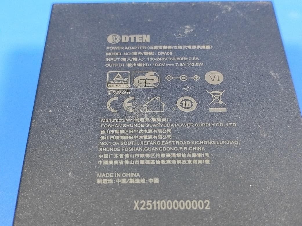
Click to zoom
Application Details
- Equipment Class
- NII - Unlicensed National Information Infrastructure TX
- Date of Grant
- Jul 17, 2026
- Application Purpose
- Original Equipment
- Equipment Note
- DTEN Mate Gen 2
- Frequency Range
- 5180.00000000 - 5240.00000000
- Company
- DTEN Inc.
- Country
- United States
Documents & Files
Document Text
Text extracted from the exhibit documents filed with the FCC. Open a document above to read the original.
Users Manual
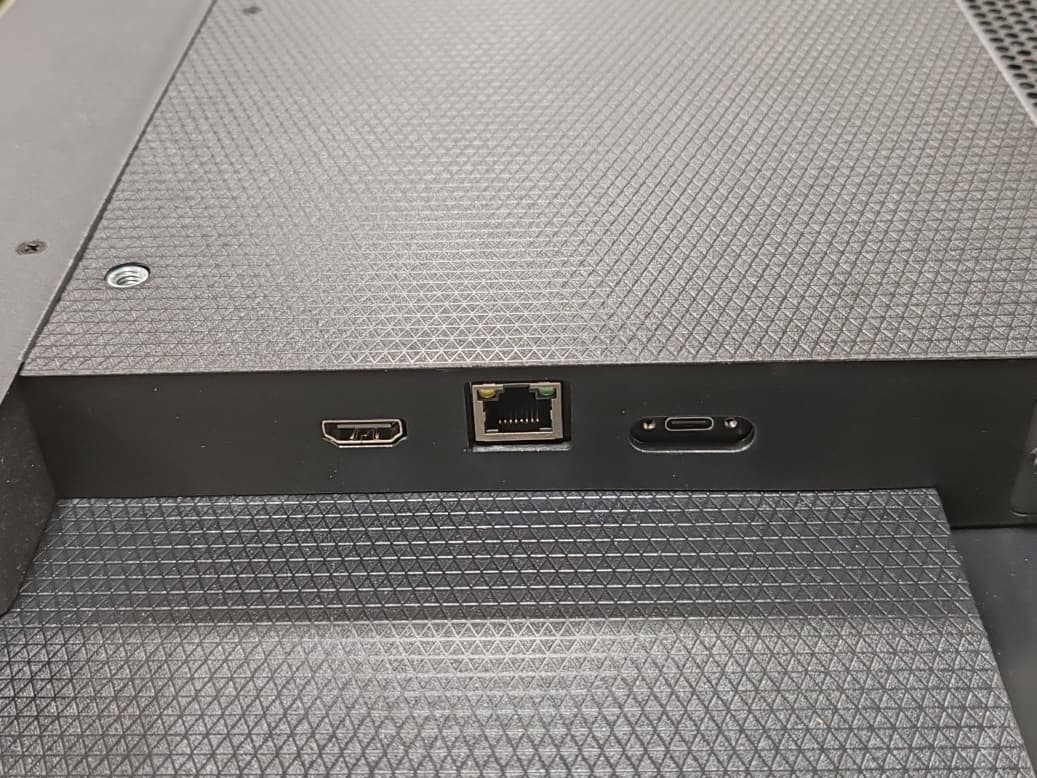
DTEN Mate Gen2 PRODUCT GUIDE Dimension & Weight Port Diagram & Connections Button Function ● Short Press: Opens the main device menu Power Supply ● The device is powered using a power adapter. ● When connected to DTEN D7X AI, the device can receive power directly through the Ethernet cable (PoE). Adjustable Viewing Angle ● Adjustable tilt angle up to 60° ● Stable hinge design supports one-hand adjustment ● Ergonomically optimized for tabletop use Built-in Microphone Array ● Six MEMS microphones ● 360-degree pickup pattern ● Operates as an extension of the main device microphone array Connection Modes Device Pairing Connect the Mate Gen 2 to the DTEN main device using an Ethernet cable. Once connected, the device will automatically pair with the main device. Use BYOD Connect a personal computer to the Mate G2 using the integrated USB-C cable to start the BYOD experience. Product Package Package content ● DTEN Mate Gen2*1 ● PoE Power Adapter*1 ● Ethernet Cable*1 ● Dongle*1 Setup & Control Connect the Mate Gen 2 to the DTEN main device using an Ethernet cable. Once connected, the devices will automatically pair, enabling the following functions: 1. Meeting Room Controller When used as a meeting room controller, the Mate Gen 2 allows users to: ● Join or start meetings ● Adjust volume, display brightness, camera settings, and layout ● Quickly access the main device menu using the side button 2. BYOD via the Main Device Connect a personal computer to the Mate Gen 2 using the integrated USB-C cable. Once connected, users can start a BYOD session and use the DTEN main device’s: ● Camera ● Microphones ● Speakers 3. Enabling the Mate G2 Microphone To enable the Mate Gen 2 microphone array, follow these steps on the main device: Step 1: Go to Dashboard > Settings > Audio Step 2: Select DTEN Mate Gen 2 Microphone and turn it on Once enabled, the Controller Mate G2 operates as an extension of the main device’s microphone array, effectively enhancing voice pickup range and clarity in medium to large meeting rooms. FCC Caution. This device complies with part 15 of the FCC Rules. Operation is subject to the following two conditions: (1) This device may not cause harmful interference, and (2) this device must accept any interference received, including interference that may cause undesired operation. Any Changes or modifications not expressly approved by the party responsible for compliance could void the user's authority to operate the equipment. Note: This equipment has been tested and found to comply with the limits for a Class B digital device, pursuant to part 15 of the FCC Rules. These limits are designed to provide reasonable protection against harmful interference in a residential installation. This equipment generates uses and can radiate radio frequency energy and, if not installed and used in accordance with the instructions, may cause harmful interference to radio communications. However, there is no guarantee that interference will not occur in a particular installation. If this equipment does cause harmful interference to radio or television reception, which can be determined by turning the equipment off and on, the user is encouraged to try to correct the interference by one or more of the following measures: -Reorient or relocate the receiving antenna. -Increase the separation between the equipment and receiver. -Connect the equipment into an outlet on a circuit different from that to which the receiver is connected. -Consult the dealer or an experienced radio/TV technician for help. FCC Radiation Exposure Statement: This equipment complies with FCC radiation exposure limits set forth for an uncontrolled environment. This equipment should be installed and operated with minimum distance 20 cm between the radiator & your body. CE Maintenance 1.Use careful with the earphone maybe excessive sound pressure from earphones and headphones can cause hearing loss. 2.Risk of explosion if battery is replaced by an incorrect type. Dispose of used batteries according to the instructions. 3.The product shall only be connected to a USB interface of version Type-C. 4.Adapter shall be installed near the equipment and shall be easily accessible. 5.EUT Operating temperature range: 0° C to 40° C . 6.Adapter: The plug considered as disconnect device of adapter Power supply and ADP(rating): Input: AC 100-240V 50/60Hz 2.5A Output: DC 19V 7.5A 7.The device complies with RF specifications when the device used at 20cm you’re your body. 8.To prevent possible hearing damage. Do not listen at high volume levels for long periods. This product may be used in the following European member states subject to the following restrictions. For products that operate in the frequency band 5.150 to 5.350 GHz, wireless access systems (WAS), including radio local area networks (RLANs), shall be restricted to indoor use. Declaration of Conformity DTEN Inc. hereby declares that this DTEN Mate Gen 2 is in compliance with the essential requirements and other relevant provisions of Directive 2014/53/EU. In accordance with Article 10(2) and Article 10(10),This product is allowed to be used in all EU member states. Frequency Bands: WLAN 802.11b/g/n/ax20: 2412~2472MHz WLAN 802.11n/ax40: 2422~2462MHz WLAN 802.11a/n/20/n40/ac20/ac40/ax20/ax40: 5150~5250 MHz WLAN 802.11a/n/20/n40/ac20/ac40/ax20/ax40: 5250~5350 MHz WLAN 802.11a/n/20/n40/ac20/ac40/ax20/ax40: 5470~5725 MHz WLAN 802.11a/n/20/n40/ac20/ac40/ax20/ax40: 5725~5850 MHz Max power: 2.4 WLAN: 17.19dBm EIRP 5.2 WLAN: 16.32dBm EIRP 5.3 WLAN: 15.45Bm EIRP 5.6 WLAN: 15.37dBm EIRP 5.8 WLAN: 13.04dBm EIRP
Test Report
The test report is effective only with both signature and specialized stamp. This report shall not be reproduced except in full without the written approval of the Laboratory. The results in this report only apply to the tested sample. Shenzhen LGT Test Service Co., Ltd. Tel: 0755-89668180 E-mail:[email protected] Web: www.lgt-cert.com Room 205, Building 13, Zone B, Zhenxiong Industrial Park, No.177, Renmin West Road, Jinsha, Kengzi Street, Pingshan District, Shenzhen, Guangdong, China Page 1 of 199 RF TEST REPORT Product Name: DTEN Mate Gen 2 Model Number: DBDLP116 FCC ID: 2AQ7Q-DBDLP116 Issued For : DTEN Inc. 2099 Gateway Place, Suite 400, San Jose, CA 95110 USA Issued By : Shenzhen LGT Test Service Co., Ltd. Room 205, Building 13, Zone B, Zhenxiong Industrial Park, No.177, Renmin West Road, Jinsha, Kengzi Street, Pingshan District, Shenzhen, Guangdong, China Report Number: LGT26A008RF06 Sample Received Date: Jan. 04, 2026 Date of Test: Jan. 04, 2026 ~ Mar. 04, 2026 Date of Issue: Mar. 20, 2026 Report No.: LGT26A008RF06 Page 2 of 199 TEST REPORT CERTIFICATION Applicant: DTEN Inc. Address: 2099 Gateway Place, Suite 400, San Jose, CA 95110 USA Manufacturer: DTEN Inc. Address: 2099 Gateway Place, Suite 400, San Jose, CA 95110 USA Product Name: DTEN Mate Gen 2 Trademark: DTEN Model Number: DBDLP116 Sample Status: Normal APPLICABLE STANDARDS STANDARD TEST RESULTS FCC Part 15.407, Subpart E ANSI C63.10-2020 + Cor.1-2023 PASS Prepared by: Approved by: Zane Shan Vita Li Engineer Technical Director Report No.: LGT26A008RF06 Page 3 of 199 Table of Contents Page 1 . SUMMARY OF TEST RESULTS 6 1.1 TEST LABORATORY 7 1.2 MEASUREMENT UNCERTAINTY 7 2 . GENERAL INFORMATION 8 2.1 GENERAL DESCRIPTION OF THE EUT 8 2.2 DESCRIPTION OF TEST MODES 10 2.3 TEST SOFTWARE AND POWER LEVEL 11 2.4 DESCRIPTION OF NECESSARY ACCESSORIES AND SUPPORT UNITS 12 2.5 EQUIPMENTS LIST FOR ALL TEST ITEMS 13 3 . EMC EMISSION TEST 15 3.1 CONDUCTED EMISSION MEASUREMENT 15 3.2 RADIATED EMISSION AND ( BANDEDGE) MEASUREMENT 19 4. POWER SPECTRAL DENSITY TEST 32 4.1 LIMIT 32 4.2 TEST PROCEDURE 32 4.3 DEVIATION FROM STANDARD 32 4.4 TEST SETUP 33 4.5 EUT OPERATION CONDITIONS 33 4.6 TEST RESULTS 33 5. BANDWIDTH MEASUREMENT 34 5.1 EMISSION BANDWIDTH (EBW) 26 BANDWID PROCEDURES / LIMIT 34 5.2 OCCUPIED BANDWIDTH ( 99%) TEST APPLIED PROCEDURES / LIMIT 35 5.3 MINIMUM EMISSION BANDWIDTH(6 DB) PROCEDURES / LIMIT 36 6. MAXIMUM CONDUCTED OUTPUT POWER 37 6.1 LIMIT 37 6.2 TEST PROCEDURE 37 6.3 DEVIATION FROM STANDARD 37 6.4 TEST SETUP 38 6.5 EUT OPERATION CONDITIONS 38 6.6 TEST RESULTS 38 7. CONDUCTED BANDEDGE 39 7.1 LIMIT 39 7.2 TEST PROCEDURE 39 7.3 DEVIATION FROM STANDARD 39 Report No.: LGT26A008RF06 Page 4 of 199 7.4 TEST SETUP 39 7.5 EUT OPERATION CONDITIONS 39 7.6 TEST RESULTS 39 8. AUTOMATICALLY DISCONTINUE TRANSMISSION 40 8.1 LIMIT OF AUTOMATICALLY DISCONTINUE TRANSMISSION 40 8.2 TEST RESULT OF AUTOMATICALLY DISCONTINUE TRANSMISSION 40 9. ANTENNA REQUIREMENT 41 9.1 STANDARD REQUIREMENT 41 9.2 EUT ANTENNA 41 APPENDIX I - TEST RESULTS 42 DUTY CYCLE 42 MAXIMUM CONDUCTED OUTPUT POWER 69 -26DB BANDWIDTH 96 OCCUPIED CHANNEL BANDWIDTH 117 MAXIMUM POWER SPECTRAL DENSITY LEVEL 144 BAND EDGE 171 -6DB BANDWIDTH 192 APPENDIX II - MEASUREMENT PHOTOS 199 Report No.: LGT26A008RF06 Page 5 of 199 Revision History Rev. Issue Date Contents 00 Mar. 20, 2026 Initial Issue Report No.: LGT26A008RF06 Page 6 of 199 1. SUMMARY OF TEST RESULTS Test procedures according to the technical standards: Part 15.407,KDB 789033 D02 General U-NII Test Procedures New Rules v02r01 FCC Part 15.407 FCC standard Test Item Results 15.207 AC Conducted Emission PASS 15.407 (a) /15.407 (e) 26dB/6dB &99% Bandwidth PASS 15.407(a) Maximum Conducted Output Power PASS 15.407(b)/15.205/15.209 Radiated Emission And (bandedge Emissions) Measurement PASS 15.407(a) Power Spectral Density PASS 15.407(c) Automatically Discontinue Transmission PASS 15.203/15.204 Antenna Requirement PASS NOTE: (1) ‘N/A’ denotes test is not applicable in this Test Report. (2) All tests are according to ANSI C63.10-2020 + Cor.1-2023. (3) Manufacturers of U-NII devices are responsible for ensuring frequency stability such that an emission is maintained within the band of operation under all conditions of normal operation as specified in the users manual. Report No.: LGT26A008RF06 Page 7 of 199 1.1 TEST LABORATORY Company Name: Shenzhen LGT Test Service Co., Ltd. Address: Room 205, Building 13, Zone B, Zhenxiong Industrial Park, No.177, Renmin West Road, Jinsha, Kengzi Street, Pingshan District, Shenzhen, Guangdong, China Accreditation Certificate: FCC Registration No.: 746540 CAB ID: CN0136 1.2 MEASUREMENT UNCERTAINTY The reported uncertainty of measurement y ± U, where expended uncertainty U is based on a standard uncertainty multiplied by a coverage factor of k=2, providing a level of confidence of approximately 95 %. No. Item Uncertainty 1 Occupied Channel Bandwidth ±0.46% 2 RF Output Power, Conducted ±0.71dB 3 Power Spectral Density, Conducted ±1.57dB 4 Unwanted Emission, Conducted ±0.63dB 5 Conducted emission ±2.80dB 6 All Emissions, Radiated (0.009-30MHz) ±2.16dB 7 All Emissions, Radiated (30MHz-1GHz) ±4.61dB 8 All Emissions, Radiated (1GHz-18GHz) ±5.49dB 9 Temperature ±0.5°C 10 Humidity ±2% 11 Duty Cycle ±2.3% Note: The measurement uncertainty is not included in the test result. Report No.: LGT26A008RF06 Page 8 of 199 2. GENERAL INFORMATION 2.1 GENERAL DESCRIPTION OF THE EUT Product Name: DTEN Mate Gen 2 Test Model Number: DBDLP116 Series Number: N/A Model Difference: N/A Product Description: Operation Frequency: IEEE 802.11a/n(HT20)/ ac(VHT20)/ax(HE20): 5.180GHz-5.240GHz IEEE 802.11n(HT40)/ ac(VHT40)/ax(HE40): 5.190GHz-5.230GHz IEEE 802.11a/n(HT20)/ ac(VHT20)/ax(HE20): 5.260GHz-5.320GHz IEEE 802.11 n(HT40)/ ac(VHT40)/ax(HE40): 5.270GHz-5.310GHz IEEE 802.11a/n(HT20)/ ac(VHT20)/ax(HE20): 5.500GHz-5.700GHz IEEE 802.11 n(HT40)/ ac(VHT40)/ax(HE40): 5.510GHz-5.670GHz IEEE 802.11a/n(HT20)/ ac(VHT20)/ax(HE20): 5.745GHz-5.…
Text truncated - open the document above for the full version.
Test Setup Photos
Page 1 of 2 Report No.: LGT26A008 Appendix - Test Setup photos Set-up for Radiated Spurious Emission, Below 1GHz Set-up for Radiated Spurious Emission, Above 1GHz Page 2 of 2 Report No.: LGT26A008 Set-up for Conducted Emission
Test Report
2.4-5.8G FPC Antenna Specification Ver: 2.0 Issued:2026.07.14 Product Name: HW01 2.4-5.8G FPC Antenna Shenzhen Shuodian Electronic Technology Co.,Ltd Add:West-J, 1A5 Floor, Jinlong Industrial City, Qilin Road, Nanshan District, Shenzhen City Antenna Type: FPC Antenna 1.Overview of product categories and product models This specification summarizes the results of the electrical test of the antenna designed for the HW01 2.4-5.8G FPC Antenna Project. The design frequency band of this antenna is 2.4G-5 8G. 2.Technical indicators and experimental equipment 2.1 Technical indicators Product electrical performance index Operating frequency range 2400MHz - 5800MHz Antenna gain 3dBi Radiation efficiency > 75 % Impedance 50 ohm Product Material Description FPC Electrolytic copper + PI Product Environment Description Working temperature -30°C ~ +85°C Storage temperature -30°C ~ +85°C 2.2 Experimental Equipment Description List Testing project Equipment 1. S Parameters 1. Return loss 2. VSWR at Network analyzer: Agilent HP8753D 2. Coupling power test 1. Transmission power 2. Receiving sensitivity Comprehensive tester: Agilent 8960 E5515C 3. Radiation pattern and gain 1. Radiation pattern 2. Antenna gain 1. Darkroom: 7x4x3 m (3D) 2. Network analyzer: Agilent 8753ES 3.Test data 3.1 Test environment 3.2 Product electrical performance test data 3.21 Test environment and equipment TEST TEMPERATURE 10°C~+30°C Relative humidity ≤80%(+40°C) Atmospheric pressure 750mmkg±30mmkg Test Equipment HP8753D network analyzer, ETS microwave anechoic chamber 3.22 Product performance test data S11 Data Sheet Marker 2400MHz 2500MH z 5150MHz 5550MHz 5850MHz Return loss -13.6 -10.4 -10.6 -21.0 -8.0 VSWR 1.5 1.8 1.8 1.1 2.3 Test curve 5.Product drawings Unit: mm FreqEffiEffiGainGainUHISDHISMaxMinDirectivityBeamwidthAttHAttV (MHz)(%)(dB)(dBi)(dBd)(%)(%)(dB)(dB)(dBi)(3dB)(dB)(dB) 240066.19-1.791.7-0.4534.29431.8951.7-10.043.496049.3149.51 241065.97-1.811.69-0.4634.15431.8151.69-9.773.56049.349.47 242067.43-1.711.85-0.335.10332.3271.85-9.593.566049.2149.44 243068.29-1.662.1-0.0535.96932.3162.1-9.443.769049.2949.51 244073.41-1.342.580.4339.04334.3672.58-9.063.929049.8149.97 245075.92-1.22.850.740.7435.1812.85-8.624.043050.2550.31 246078.91-1.033.000.8842.40736.53.03-7.994.063050.4250.54 247076.44-1.172.760.6141.03435.4062.76-7.853.923050.6650.7 248077.16-1.132.650.541.2435.9232.65-7.843.783050.7250.69 249077.12-1.132.430.2841.10536.0192.43-7.713.563050.7750.66 250075.75-1.212.260.1140.36335.3882.26-7.593.473050.6950.54 Passive Test For WIFI2.4 Appendix A FPC ANT-2.4G FreqEffiEffiGainGainUHISDHISMaxMinDirectivityBeamwidthAttHAttV (MHz)(%)(dB)(dBi)(dBd)(%)(%)(dB)(dB)(dBi)(3dB)(dB)(dB) 515046.68-3.312.660.5124.16522.522.66-16.925.9760 61.6162.28 516048.63-3.132.920.7725.0923.542.92-17.646.0560 60.9561.29 517053.21-2.74 2.91.0527.13226.0763.2-16.845.9460 61.2561.54 518051.63-2.87 2.780.9326.50525.1293.08-17.55.9560 60.6460.99 519048.3-3.162.730.5824.61123.6852.73-19.265.8960 60.2760.69 520044.11-3.552.270.1222.45421.6582.27-18.255.8260 60.1860.46 521049.62-3.042.710.5625.27924.3362.71-18.475.7560 60.4160.84 522051.23-2.92.770.6225.93725.2972.77-19.155.6860 60.9761.46 523052.3-2.812.680.5326.52125.7832.68-18.465.560 61.2261.57 524058.88-2.3 2.781.0330.02628.853.18-17.865.4860 61.2561.8 525052.85-2.772.610.4626.87225.9772.61-18.765.3860 60.1160.58 526050.44-2.972.260.1125.16425.2752.26-21.025.2360 59.9560.38 527051.23-2.912.05-0.125.94225.2852.05-22.494.9660 59.7260.27 528056.14-2.512.530.3828.32927.8082.53-19.215.0460 60.2660.8 529055.18-2.582.440.2927.69727.4852.44-20.275.0260 61.1761.71 530050.71-2.951.97-0.1825.23125.4811.97-19.194.9260 60.4761.03 531057.17-2.432.350.228.35528.8142.35-18.44.7860 60.8461.39 532056.79-2.462.360.2128.03928.7552.36-16.954.8260 60.0960.69 533055.47-2.562.09-0.0627.29828.1672.09-20.684.6560 59.8860.38 534058.01-2.372.30.1528.41929.5872.3 -18.544.6660 60.4260.98 535059.32-2.272.360.2128.96330.3572.36-20.264.6360 60.7161.23 536052.11-2.831.95-0.225.40226.711.95-19.914.7860 61.2361.7 537056.41-2.491.98-0.1727.13929.2711.98-16.264.4760 60.8861.42 538057.5-2.42.350.227.77829.7222.35-15.414.7660 60.9761.35 539055.29-2.572.390.2426.7728.5192.39-17.464.966060.460.69 540068.1-1.672.730.8832.88435.2113.03-204.760 60.9361.3 541061.61-2.12.780.6329.69331.9162.78-19.064.8860 61.0261.19 542057.84-2.382.490.3427.55630.2882.49-18.514.8660 60.9661.16 543054.45-2.642.270.1225.71628.7372.27-15.234.9160 61.5561.71 544058.69-2.312.780.9328.38630.3053.08-16.325.3960 61.9961.75 545062.05-2.072.720.9729.78732.2643.12-18.345.193062.262.15 546060.45-2.192.810.8628.5931.8553.01-14.635.1960 61.9761.69 547058.35-2.342.810.9628.22930.1163.11-14.565.4560 61.9461.64 548056.73-2.462.850.727.39929.3282.85-16.415.3160 61.7861.34 549057.21-2.432.70.5527.32929.8832.7-15.415.1360 61.9661.39 550058.83-2.32.91.0528.55730.2763.2-16.645.560 62.8762.13 551055.62-2.55 3 0.8527.02128.6033 -15.015.5430 63.2862.46 552064.33-1.92 2 . 8 9 1.2430.75833.5713.39-14.915.3130 63.8963.03 553059.53-2.252.910.8628.63330.8973.01-15.235.2630 63.5262.57 554057.97-2.372.710.5627.74130.2262.71-16.265.0830 63.6362.47 555066.11-1.82.711.2632.0934.0223.41-21.495.2130 63.7662.77 556065.29-1.852.761.1131.6133.6813.26-17.675.1130 63.7862.73 557061.63-2.12.850.729.58832.0412.85-16.74.9530 64.3163.18 558060.88-2.15 2.910.8628.90731.9773.01-15.485.163064.163.25 559060.02-2.222.881.1328.6231.3963.28-15.585.530 64.5663.53 560061.91-2.08 2.91 0.8530.25331.6593 -23.055.0830 64.2363.42 561063.59-1.972.740.5930.62532.9662.74-19.084.7130 63.8863.07 562061.65-2.12.90.7529.69731.9492.9-19.14530 63.6662.89 563056.57-2.472.680.5327.29329.282.68-17.145.1530 63.5662.84 564054.98-2.62.890.7426.44228.5382.89-16.445.4930 63.9663.37 Passive Test For WIFI5.8 Appendix B FPC ANT-5G 565062.77-2.022.900.930.41532.3563.05-21.565.0830 64.2863.67 566060.33-2.192.440.2929.35130.9832.44-17.314.6330 63.9463.43 567061.21-2.132.770.6229.84531.3662.77-15.694.930 63.3662.77 568060.69-2.17 2.940.9929.6123…
Text truncated - open the document above for the full version.
Test Report
The test report is effective only with both signature and specialized stamp. This report shall not be reproduced except in full without the written approval of the Laboratory. The results in this report only apply to the tested sample. Shenzhen LGT Test Service Co., Ltd. Tel: 0755-89668180 E-mail:[email protected] Web: www.lgt-cert.com Room 205, Building 13, Zone B, Zhenxiong Industrial Park, No.177, Renmin West Road, Jinsha, Kengzi Street, Pingshan District, Shenzhen, Guangdong, China Page 1 of 20 RF TEST REPORT Product Name: DTEN Mate Gen 2 Model Number: DBDLP116 FCC ID: 2AQ7Q-DBDLP116 Issued For : DTEN Inc. 2099 Gateway Place, Suite 400, San Jose, CA 95110 USA Issued By : Shenzhen LGT Test Service Co., Ltd. Room 205, Building 13, Zone B, Zhenxiong Industrial Park, No.177, Renmin West Road, Jinsha, Kengzi Street, Pingshan District, Shenzhen, Guangdong, China Report Number: LGT26A008RF07 Sample Received Date: Jan. 04, 2026 Date of Test: Jan. 04, 2026 ~ Mar. 04, 2026 Date of Issue: Mar. 20, 2026 Report No.: LGT26A008RF07 Page 2 of 20 TEST REPORT CERTIFICATION Applicant: DTEN Inc. Address: 2099 Gateway Place, Suite 400, San Jose, CA 95110 USA Manufacturer: DTEN Inc. Address: 2099 Gateway Place, Suite 400, San Jose, CA 95110 USA Product Name: DTEN Mate Gen 2 Trademark: DTEN Model Number: DBDLP116 Sample Status: Normal APPLICABLE STANDARDS STANDARD TEST RESULTS FCC Part 15.407, KDB 789033 D02 ANSI C63.10-2020 + COR.1-2023 PASS Prepared by: Approved by: Zane Shan Vita Li Engineer Technical Director Report No.: LGT26A008RF07 Page 3 of 20 Table of Contents 1. SUMMARY OF TEST RESULTS 5 1.1 TEST LABORATORY 5 1.2 MEASUREMENT UNCERTAINTY 5 2. GENERAL INFORMATION 6 2.1 GENERAL DESCRIPTION OF THE EUT 6 2.2 EQUIPMENT UNDER TEST (EUT) DETAILS 8 2.3 TEST CONDITIONS AND CHANNEL 8 2.4 DFS MEASUREMENT INSTRUMENTATION 9 2.5 EQUIPMENTS LIST FOR ALL TEST ITEMS 10 3. DFS PARAMETERS 11 3.1 DFS PARAMETERS 11 3.2 DFS MEASUREMENT METHODS 15 Non-Occupancy 18 Shutdown Time 19 Report No.: LGT26A008RF07 Page 4 of 20 Revision History Rev. Issue Date Contents 00 Mar. 20, 2026 Initial Issue Report No.: LGT26A008RF07 Page 5 of 20 1. SUMMARY OF TEST RESULTS Test procedures according to the technical standards: KDB 905462 D02 UNII DFS Compliance Procedures New Rules v02 and 905462 D03 UNII Clients Without Radar Detection New Rules v01r02 Part 15.407 Requirement Operational Mode RESULT Master Client Non-Occupancy Period Yes Yes Pass DFS Detection Threshold Yes Not required Not required Channel Availability Check Time Yes Not required Not required Channel Closing Transmission Time Yes Yes Pass Channel Move Time Yes Yes Pass U-NII Detection Bandwidth Yes Not required Not required 1.1 TEST LABORATORY Company Name: Shenzhen LGT Test Service Co., Ltd. Address: Room 205, Building 13, Zone B, Zhenxiong Industrial Park, No.177, Renmin West Road, Jinsha, Kengzi Street, Pingshan District, Shenzhen, Guangdong, China Accreditation Certificate: FCC Registration No.: 746540 CAB ID: CN0136 1.2 MEASUREMENT UNCERTAINTY The reported uncertainty of measurement y ± U, where expended uncertainty U is based on a standard uncertainty multiplied by a coverage factor of k=2, providing a level of confidence of approximately 95 %. No. Item Uncertainty 1 DFS Threshold (radiated) ±1.50dB 2 DFS Threshold (conducted) ±1.45dB 3 Temperature ±0.5°C 4 Humidity ±2% Note: The measurement uncertainty is not included in the test result. Report No.: LGT26A008RF07 Page 6 of 20 2. GENERAL INFORMATION 2.1 GENERAL DESCRIPTION OF THE EUT Product Name: DTEN Mate Gen 2 Test Model Number: DBDLP116 Series Number: N/A Model Difference: N/A Product Description: Operation Frequency: 802.11a/n/ac/ax (20):5260 MHz -5320 MHz 802.11a/n/ac/ax (40):5270 MHz -5310 MHz 802.11a/n/ac/ax (20):5500 MHz -5700 MHz 802.11a/n/ac/ax (40):5510 MHz -5670 MHz Modulation Type: 802.11a(OFDM): BPSK, QPSK, 16-QAM, 64-QAM 802.11n(OFDM): BPSK, QPSK, 16-QAM, 64-QAM 802.11ac (OFDM): BPSK, QPSK, 16-QAM, 64-QAM, 256-QAM 802.11ax(OFDM, OFDMA): BPSK, QPSK, 16-QAM, 64-QAM, 256-QAM, 1024QAM Number Of Channel Please see Note 2. Antenna Gain (Peak) 3dBi Based on the application, features, or specification exhibited in User’s Manual, the EUT is considered as an ITE/Computing Device. More details of EUT technical specification, please refer to the User’s Manual. Channel List: Refer to below Adapter: Input: AC 100-240V 50/60Hz 2.5A Output: DC 19V 7.5A POE Power Supply: DC48V 0.42A Hardware Version: P2 Software Version: V4.1.260702 Note: 1. For a more detailed features description, please refer to the manufacturer’s specifications or the User Manual, the antenna information refer the manufacturer provide report, applicable only to the tested sample identified in the report. Report No.: LGT26A008RF07 Page 7 of 20 2. Operation Frequency of channel 5.260GHz-5.320GHz 5.500GHz-5.720GHz Channel Frequency Channel Frequency 52 5260 100 5500 54 5270 102 5510 56 5280 104 5520 58 5290 106 5530 60 5300 108 5540 62 5310 110 5550 64 5320 112 5560 116 5580 118 5590 120 5600 122 5610 124 5620 126 5630 128 5640 132 5660 134 5670 136 5680 140 5700 Remark: 1. The EUT not support TPC function, Radar detection and hotspot. 2. The master device fixed the test mode and working channel on the background management page, the client device is connected to the wireless network sent by the master device, it takes 120 seconds for the master device to fully boot up, and 8.0 seconds for the client device. Report No.: LGT26A008RF07 Page 8 of 20 2.2 EQUIPMENT UNDER TEST (EUT) DETAILS The manufacturer declared values for the EUT operational characteristics that affect DFS are as follows Operating Modes (5250 – 5350 MHz, 5470 – 5725 MHz) Master Device Client Device (no In Service Monitoring, no Ad-Hoc mode) Client Device with In-Service Monitoring Antenna Gains / EIRP (5250 – 5350 MHz, 5470 – 5725 MHz) 5250 – 5350 MHz 5470 – 5725 MHz Lowest Antenna Gain (dBi) 3 3 Highest Antenna Gain (dBi) 3 3 DFS Detection Threshold (dBm) -62 Channel Protocol IP Ba…
Text truncated - open the document above for the full version.
Test Report
Report No.: LGT26A008RF06 Page 181 of 199 Band Edge NVNT ac40 5190MHz Low Band Edge NVNT ac40 5230MHz High Band Edge NVNT ac40 5270MHz Low Report No.: LGT26A008RF06 Page 182 of 199 Band Edge NVNT ac40 5310MHz High Band Edge NVNT ac40 5510MHz Low Band Edge NVNT ac40 5670MHz High Report No.: LGT26A008RF06 Page 183 of 199 Band Edge NVNT ax20 5180MHz Low Band Edge NVNT ax20 5240MHz High Band Edge NVNT ax20 5260MHz Low Report No.: LGT26A008RF06 Page 184 of 199 Band Edge NVNT ax20 5320MHz High Band Edge NVNT ax20 5500MHz Low Band Edge NVNT ax20 5700MHz High Report No.: LGT26A008RF06 Page 185 of 199 Band Edge NVNT ax40 5190MHz Low Band Edge NVNT ax40 5230MHz High Band Edge NVNT ax40 5270MHz Low Report No.: LGT26A008RF06 Page 186 of 199 Band Edge NVNT ax40 5310MHz High Band Edge NVNT ax40 5510MHz Low Band Edge NVNT ax40 5670MHz High Report No.: LGT26A008RF06 Page 187 of 199 Band Edge NVNT a 5745MHz Low Band Edge NVNT a 5825MHz High Band Edge NVNT n20 5745MHz Low Report No.: LGT26A008RF06 Page 188 of 199 Band Edge NVNT n20 5825MHz High Band Edge NVNT n40 5755MHz Low Band Edge NVNT n40 5795MHz High Report No.: LGT26A008RF06 Page 189 of 199 Band Edge NVNT ac20 5745MHz Low Band Edge NVNT ac20 5825MHz High Band Edge NVNT ac40 5755MHz Low Report No.: LGT26A008RF06 Page 190 of 199 Band Edge NVNT ac40 5795MHz High Band Edge NVNT ax20 5745MHz Low Band Edge NVNT ax20 5825MHz High Report No.: LGT26A008RF06 Page 191 of 199 Band Edge NVNT ax40 5755MHz Low Band Edge NVNT ax40 5795MHz High Report No.: LGT26A008RF06 Page 192 of 199 -6dB Bandwidth Condition Mode Frequency (MHz) -6 dB Bandwidth (MHz) Limit -6 dB Bandwidth (MHz) Verdict NVNT a 5745 16.441 0.5 Pass NVNT a 5785 16.426 0.5 Pass NVNT a 5825 16.443 0.5 Pass NVNT n20 5745 17.631 0.5 Pass NVNT n20 5785 17.634 0.5 Pass NVNT n20 5825 17.643 0.5 Pass NVNT n40 5755 36.366 0.5 Pass NVNT n40 5795 36.408 0.5 Pass NVNT ac20 5745 17.667 0.5 Pass NVNT ac20 5785 17.624 0.5 Pass NVNT ac20 5825 17.666 0.5 Pass NVNT ac40 5755 36.402 0.5 Pass NVNT ac40 5795 36.393 0.5 Pass NVNT ax20 5745 18.793 0.5 Pass NVNT ax20 5785 18.998 0.5 Pass NVNT ax20 5825 18.999 0.5 Pass NVNT ax40 5755 37.97 0.5 Pass NVNT ax40 5795 38.009 0.5 Pass Report No.: LGT26A008RF06 Page 193 of 199 Test Graphs -6dB Bandwidth NVNT a 5745MHz -6dB Bandwidth NVNT a 5785MHz -6dB Bandwidth NVNT a 5825MHz Report No.: LGT26A008RF06 Page 194 of 199 -6dB Bandwidth NVNT n20 5745MHz -6dB Bandwidth NVNT n20 5785MHz -6dB Bandwidth NVNT n20 5825MHz Report No.: LGT26A008RF06 Page 195 of 199 -6dB Bandwidth NVNT n40 5755MHz -6dB Bandwidth NVNT n40 5795MHz -6dB Bandwidth NVNT ac20 5745MHz Report No.: LGT26A008RF06 Page 196 of 199 -6dB Bandwidth NVNT ac20 5785MHz -6dB Bandwidth NVNT ac20 5825MHz -6dB Bandwidth NVNT ac40 5755MHz Report No.: LGT26A008RF06 Page 197 of 199 -6dB Bandwidth NVNT ac40 5795MHz -6dB Bandwidth NVNT ax20 5745MHz -6dB Bandwidth NVNT ax20 5785MHz Report No.: LGT26A008RF06 Page 198 of 199 -6dB Bandwidth NVNT ax20 5825MHz -6dB Bandwidth NVNT ax40 5755MHz -6dB Bandwidth NVNT ax40 5795MHz Report No.: LGT26A008RF06 Page 199 of 199 APPENDIX II - MEASUREMENT PHOTOS Note: Please see the attached RF_Test Setup photos for FCC ID. ※※※※※END OF THE REPORT※※※※※
Test Report
Report No.: LGT26A008RF06 Page 149 of 199 PSD NVNT n20 5180MHz PSD NVNT n20 5200MHz PSD NVNT n20 5240MHz Report No.: LGT26A008RF06 Page 150 of 199 PSD NVNT n20 5260MHz PSD NVNT n20 5300MHz PSD NVNT n20 5320MHz Report No.: LGT26A008RF06 Page 151 of 199 PSD NVNT n20 5500MHz PSD NVNT n20 5580MHz PSD NVNT n20 5700MHz Report No.: LGT26A008RF06 Page 152 of 199 PSD NVNT n40 5190MHz PSD NVNT n40 5230MHz PSD NVNT n40 5270MHz Report No.: LGT26A008RF06 Page 153 of 199 PSD NVNT n40 5310MHz PSD NVNT n40 5510MHz PSD NVNT n40 5550MHz Report No.: LGT26A008RF06 Page 154 of 199 PSD NVNT n40 5670MHz PSD NVNT ac20 5180MHz PSD NVNT ac20 5200MHz Report No.: LGT26A008RF06 Page 155 of 199 PSD NVNT ac20 5240MHz PSD NVNT ac20 5260MHz PSD NVNT ac20 5300MHz Report No.: LGT26A008RF06 Page 156 of 199 PSD NVNT ac20 5320MHz PSD NVNT ac20 5500MHz PSD NVNT ac20 5580MHz Report No.: LGT26A008RF06 Page 157 of 199 PSD NVNT ac20 5700MHz PSD NVNT ac40 5190MHz PSD NVNT ac40 5230MHz Report No.: LGT26A008RF06 Page 158 of 199 PSD NVNT ac40 5270MHz PSD NVNT ac40 5310MHz PSD NVNT ac40 5510MHz Report No.: LGT26A008RF06 Page 159 of 199 PSD NVNT ac40 5550MHz PSD NVNT ac40 5670MHz PSD NVNT ax20 5180MHz Report No.: LGT26A008RF06 Page 160 of 199 PSD NVNT ax20 5200MHz PSD NVNT ax20 5240MHz PSD NVNT ax20 5260MHz Report No.: LGT26A008RF06 Page 161 of 199 PSD NVNT ax20 5300MHz PSD NVNT ax20 5320MHz PSD NVNT ax20 5500MHz Report No.: LGT26A008RF06 Page 162 of 199 PSD NVNT ax20 5580MHz PSD NVNT ax20 5700MHz PSD NVNT ax40 5190MHz Report No.: LGT26A008RF06 Page 163 of 199 PSD NVNT ax40 5230MHz PSD NVNT ax40 5270MHz PSD NVNT ax40 5310MHz Report No.: LGT26A008RF06 Page 164 of 199 PSD NVNT ax40 5510MHz PSD NVNT ax40 5550MHz PSD NVNT ax40 5670MHz Report No.: LGT26A008RF06 Page 165 of 199 PSD NVNT a 5745MHz PSD NVNT a 5785MHz PSD NVNT a 5825MHz Report No.: LGT26A008RF06 Page 166 of 199 PSD NVNT n20 5745MHz PSD NVNT n20 5785MHz PSD NVNT n20 5825MHz Report No.: LGT26A008RF06 Page 167 of 199 PSD NVNT n40 5755MHz PSD NVNT n40 5795MHz PSD NVNT ac20 5745MHz Report No.: LGT26A008RF06 Page 168 of 199 PSD NVNT ac20 5785MHz PSD NVNT ac20 5825MHz PSD NVNT ac40 5755MHz Report No.: LGT26A008RF06 Page 169 of 199 PSD NVNT ac40 5795MHz PSD NVNT ax20 5745MHz PSD NVNT ax20 5785MHz Report No.: LGT26A008RF06 Page 170 of 199 PSD NVNT ax20 5825MHz PSD NVNT ax40 5755MHz PSD NVNT ax40 5795MHz Report No.: LGT26A008RF06 Page 171 of 199 Band Edge Condition Mode Frequency (MHz) Max Value (dBm) Limit (dBm) Verdict NVNT a 5180 -30.56 -27 Pass NVNT a 5240 -41.28 -27 Pass NVNT a 5260 -39.46 -27 Pass NVNT a 5320 -33.08 -27 Pass NVNT a 5500 -39.95 -27 Pass NVNT a 5700 -29.84 -27 Pass NVNT n20 5180 -32.01 -27 Pass NVNT n20 5240 -41.12 -27 Pass NVNT n20 5260 -38.9 -27 Pass NVNT n20 5320 -39.17 -27 Pass NVNT n20 5500 -39.74 -27 Pass NVNT n20 5700 -32.7 -27 Pass NVNT n40 5190 -32.35 -27 Pass NVNT n40 5230 -38.43 -27 Pass NVNT n40 5270 -39.27 -27 Pass NVNT n40 5310 -33.62 -27 Pass NVNT n40 5510 -34.01 -27 Pass NVNT n40 5670 -35.95…
Text truncated - open the document above for the full version.
Contact Information
Applicant
Ning Zhang(Product Design Engineer)
[email protected]Fax: 402-405-9601
Technical Contact
Test Firm
Shenzhen LGT Test Service Co., Ltd.Wen Wen
Technical Specifications
| # | Rule Parts | Frequency Range | Power Output |
|---|---|---|---|
| 1 | 15E | 5.18 GHz - 5.24 GHz | 25.60 mW |
| 2 | 15E | 5.26 GHz - 5.32 GHz | 24.00 mW |
| 3 | 15E | 5.50 GHz - 5.70 GHz | 17.50 mW |
| 4 | 15E | 5.75 GHz - 5.83 GHz | 23.80 mW |
Other Applications from DTEN Inc.
2AQ7Q-DB7U1R475
Aug 12, 2026DTEN D7X AI 75
Equipment Class
DXX - Part 15 Low Power Communication Device Transmitter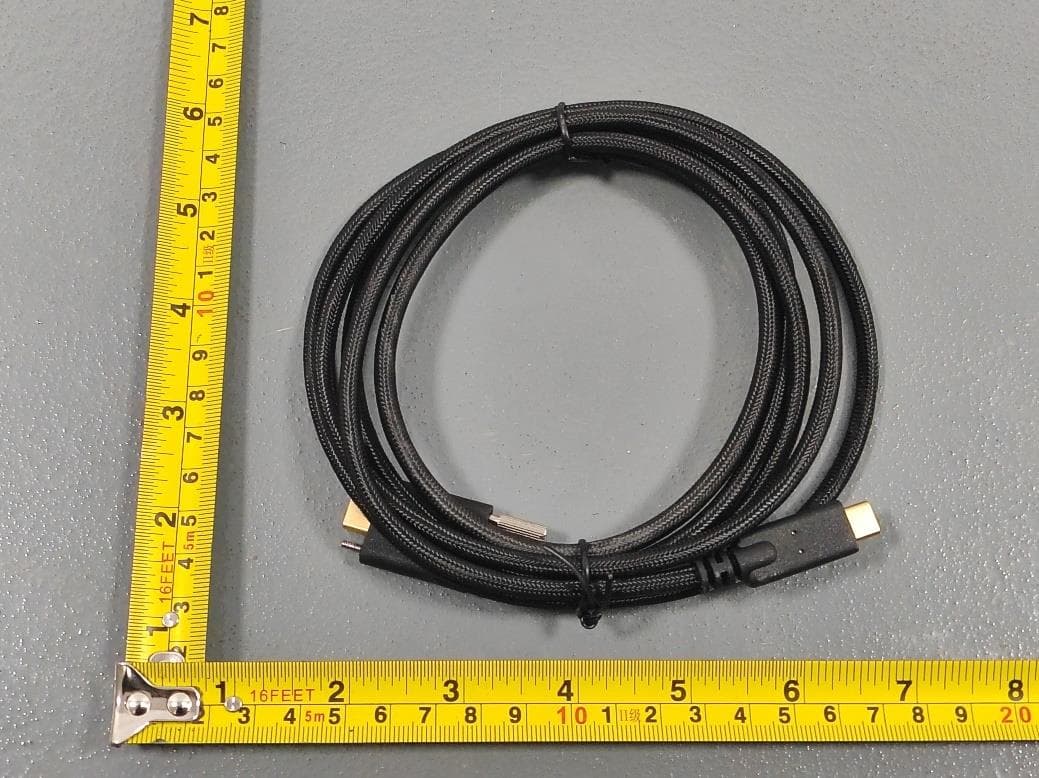
2AQ7Q-DB7U1R455
Mar 05, 2026DTEN D7X AI 55
Equipment Class
DXX - Part 15 Low Power Communication Device Transmitter
2AQ7Q-DAWLAPD01
Sep 11, 2025DTEN Relay Speakers
Equipment Class
DTS - Digital Transmission System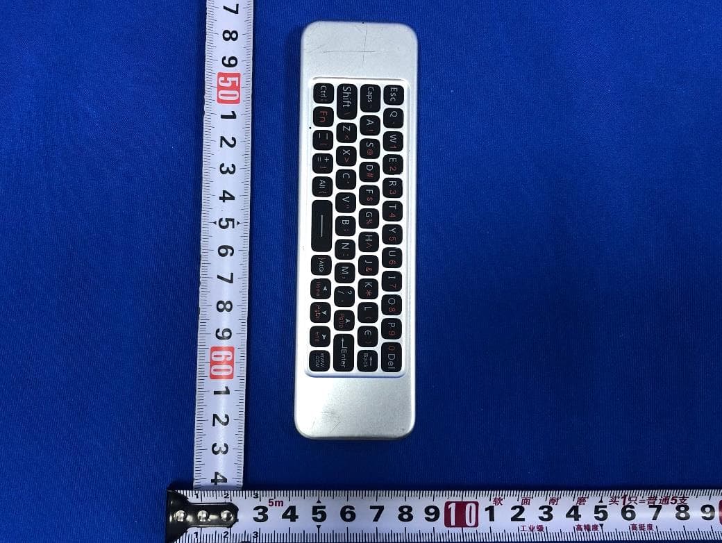
2AQ7Q-DARCWL01
Dec 19, 2023DTEN Remote Control
Equipment Class
JBP - Part 15 Class B Computing Device Peripheral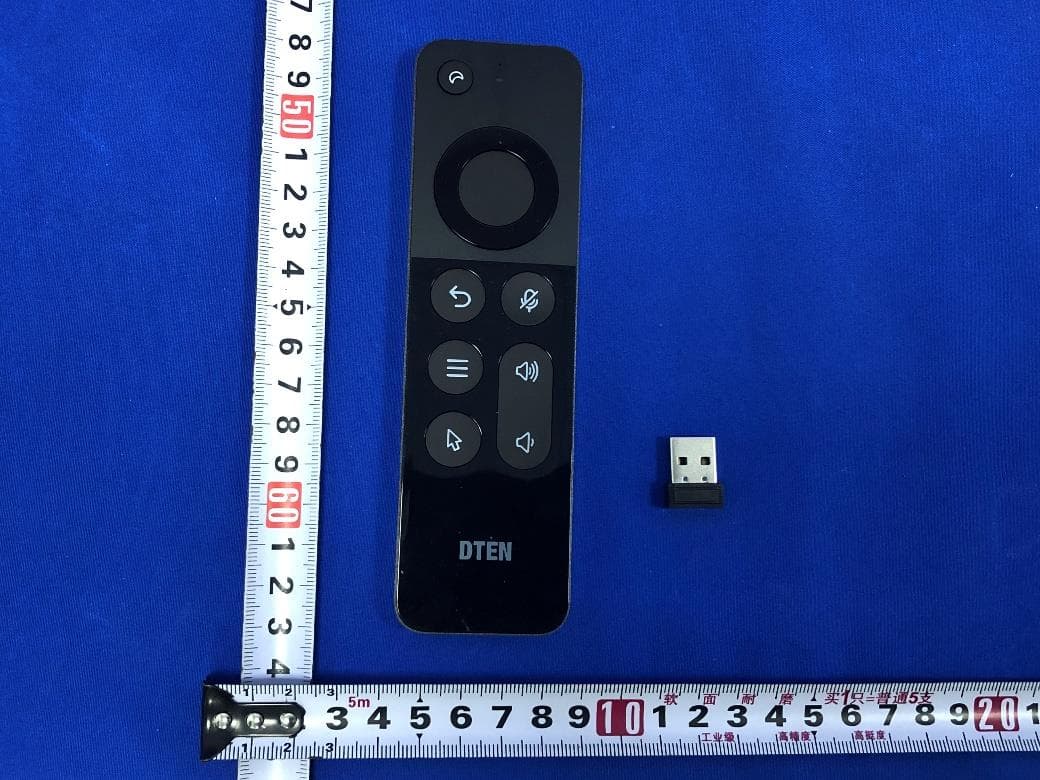
2AQ7Q-DARCWLMD01
Dec 19, 2023DTEN Remote Control Dongle
Equipment Class
DTS - Digital Transmission System