2AQ8NMB-1True Wireless Charging. The worlds first contactless wireless charging product for mobile devices.
Yank Technologies Inc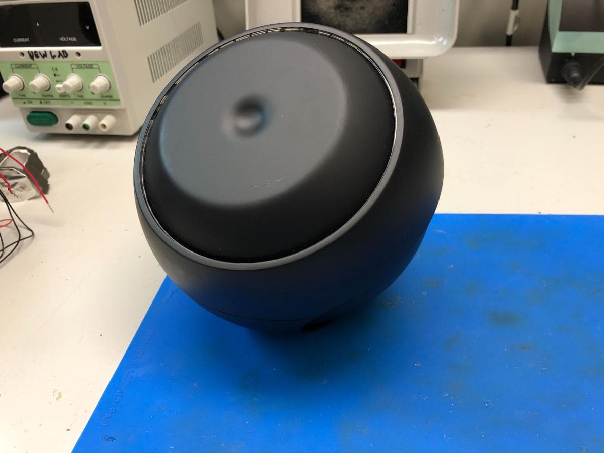
Click to zoom
Application Details
- Equipment Class
- 8CC - Part 18 Consumer Device
- Date of Grant
- Apr 07, 2020
- Application Purpose
- Original Equipment
- Date of Application
- Apr 07, 2020
- Equipment Note
- True Wireless Charging. The worlds first contactless wireless charging product for mobile devices.
- Frequency Range
- 6.78000000 - 6.78000000
- Company
- Yank Technologies Inc
- Country
- United States
Documents & Files
Document Text
Text extracted from the exhibit documents filed with the FCC. Open a document above to read the original.
External Photos
Yank Technologies, Inc. 19 Morris Ave., Bldg. 128 Brooklyn, NY 11205 (845) 598-4648 [email protected] Exterior Photos Front of MotherBox: Yank Technologies, Inc. 19 Morris Ave., Bldg. 128 Brooklyn, NY 11205 (845) 598-4648 [email protected] Back of MotherBox: FCC label being placed on the back of every MotherBox unit like in the image shown above.
External Photos
Yank Technologies, Inc. 19 Morris Ave., Bldg. 128 Brooklyn, NY 11205 (845) 598-4648 [email protected] FRONT OF THE MOTHERBOX: Yank Technologies, Inc. 19 Morris Ave., Bldg. 128 Brooklyn, NY 11205 (845) 598-4648 [email protected] SIDE VIEW OF THE MOTHERBOX: Yank Technologies, Inc. 19 Morris Ave., Bldg. 128 Brooklyn, NY 11205 (845) 598-4648 [email protected] BOTTOM VIEW OF THE MOTHERBOX: Yank Technologies, Inc. 19 Morris Ave., Bldg. 128 Brooklyn, NY 11205 (845) 598-4648 [email protected] TOP VIEW OF THE MOTHERBOX: Yank Technologies, Inc. 19 Morris Ave., Bldg. 128 Brooklyn, NY 11205 (845) 598-4648 [email protected] SECOND SIDE VIEW OF THE MOTHERBOX: Yank Technologies, Inc. 19 Morris Ave., Bldg. 128 Brooklyn, NY 11205 (845) 598-4648 [email protected] BACK VIEW OF THE MOTHERBOX:
ID Label/Location Info
The label will be permanently pressed onto the product like the image below:
Internal Photos
Yank Technologies, Inc. 19 Morris Ave., Bldg. 128 Brooklyn, NY 11205 (845) 598-4648 [email protected] Interior Photos Front of Power PCB (DC input jack PCB): Yank Technologies, Inc. 19 Morris Ave., Bldg. 128 Brooklyn, NY 11205 (845) 598-4648 [email protected] Back of Power PCB (DC input jack PCB): Yank Technologies, Inc. 19 Morris Ave., Bldg. 128 Brooklyn, NY 11205 (845) 598-4648 [email protected] Amplifier PCB Front: Yank Technologies, Inc. 19 Morris Ave., Bldg. 128 Brooklyn, NY 11205 (845) 598-4648 [email protected] Amplifier PCB Back: Yank Technologies, Inc. 19 Morris Ave., Bldg. 128 Brooklyn, NY 11205 (845) 598-4648 [email protected] First Filter Front: Yank Technologies, Inc. 19 Morris Ave., Bldg. 128 Brooklyn, NY 11205 (845) 598-4648 [email protected] First Filter Back: Yank Technologies, Inc. 19 Morris Ave., Bldg. 128 Brooklyn, NY 11205 (845) 598-4648 [email protected] Second Filter Front: Yank Technologies, Inc. 19 Morris Ave., Bldg. 128 Brooklyn, NY 11205 (845) 598-4648 [email protected] Second Filter Back: Yank Technologies, Inc. 19 Morris Ave., Bldg. 128 Brooklyn, NY 11205 (845) 598-4648 [email protected] Antenna Termination PCB Front: Yank Technologies, Inc. 19 Morris Ave., Bldg. 128 Brooklyn, NY 11205 (845) 598-4648 [email protected] Antenna Termination PCB Back: Yank Technologies, Inc. 19 Morris Ave., Bldg. 128 Brooklyn, NY 11205 (845) 598-4648 [email protected] MotherBox Internal PCB Assembly: This is the Power PCB (DC jack input PCB) placed inside the MotherBox prior to the antenna array and remainder PCBs. Yank Technologies, Inc. 19 Morris Ave., Bldg. 128 Brooklyn, NY 11205 (845) 598-4648 [email protected] MotherBox Internal PCB Assembly Photo 2:
RF Exposure Info
DUT and SAR Set-up Photos Front View of the DUT Setup Photos Body Exposure Conditions Edge 1 Edge 2 Edge 3 Edge 4 w/ Mother Box Receiver
RF Exposure Info
Plot No. 1 Test Laboratory: UL Verification Services Inc. SAR Lab 1 Date/Time: 9/6/2019 10:41:37 AM 20190906_SystemPerformanceCheck-CLA-6 SN 1005 Frequency: 6 MHz; Duty Cycle: 1:1; Room Ambient Temperature: 24.0C; Liquid Temperature: 23.0C Medium parameters used: f = 6 MHz; σ = 0.72 S/m; ε r = 56.175; ρ = 1000 kg/m 3 DASY5 Configuration: - Area Scan Setting: Find Secondary Maximum Within: 2.0 dB and with a peak SAR value greater than 0.0012W/kg - Electronics: DAE4 Sn1544; Calibrated: 3/19/2019 - Probe: EX3DV4 - SN3885; ConvF(18.2, 18.2, 18.2) @ 6 MHz; Calibrated: 9/18/2018 - Sensor-Surface: 1.4mm (Mechanical Surface Detection) - Phantom: ELI Back; Type: QDOVA002AA; Serial: TP:1248 Head/Pin=100 mW/Area Scan (9x9x1): Measurement grid: dx=15mm, dy=15mm Maximum value of SAR (measured) = 0.0283 W/kg Head/Pin=100 mW/Zoom Scan (9x10x7)/Cube 0: Measurement grid: dx=4mm, dy=4mm, dz=1.4mm Reference Value = 6.330 V/m; Power Drift = -0.03 dB Peak SAR (extrapolated) = 0.0390 W/kg SAR(1 g) = 0.019 W/kg; SAR(10 g) = 0.012 W/kg Maximum value of SAR (measured) = 0.0289 W/kg 0 dB = 0.0289 W/kg = -15.39 dBW/kg Plot No. 2 Test Laboratory: UL Verification Services Inc. SAR Lab 1 Date/Time: 9/6/2019 11:06:40 AM 20190906_SystemPerformanceCheck-CLA-6 SN 1005 Frequency: 6 MHz; Duty Cycle: 1:1 Head/Pin=100 mW/Z Scan (1x1x21): Measurement grid: dx=20mm, dy=20mm, dz=5mm Maximum value of SAR (measured) = 0.0236 W/kg
RF Exposure Info
Plot No. 1 Test Laboratory: UL Verification Services Inc., SAR Lab 1 Date/Time: 9/6/2019 11:53:23 AM 6MHz CW Frequency: 6 MHz; Duty Cycle: 1:1; Room Ambient Temperature: 24.0°C; Liquid Temperature: 23.0°C Medium parameters used: f = 6 MHz; σ = 0.779 S/m; ε r = 49.936; ρ = 1000 kg/m 3 DASY5 Configuration: - Area Scan Setting: Find Secondary Maximum Within: 2.0 dB and with a peak SAR value greater than 0.0012W/kg - Electronics: DAE4 Sn1544; Calibrated: 3/19/2019 - Probe: EX3DV4 - SN3885; ConvF(18.2, 18.2, 18.2) @ 6 MHz; Calibrated: 9/18/2018 - Sensor-Surface: 1.4mm (Mechanical Surface Detection) - Phantom: ELI Back; Type: QDOVA002AA; Serial: TP:1248 Standalone/6MHz_CW_Edge 1_5cm/Area Scan (14x14x1): Measurement grid: dx=15mm, dy=15mm Maximum value of SAR (measured) = 0.0648 W/kg Standalone/6MHz_CW_Edge 1_5cm/Zoom Scan (5x5x7)/Cube 0: Measurement grid: dx=8mm, dy=8mm, dz=5mm Reference Value = 8.548 V/m; Power Drift = 0.03 dB Peak SAR (extrapolated) = 0.0750 W/kg SAR(1 g) = 0.055 W/kg; SAR(10 g) = 0.044 W/kg Maximum value of SAR (measured) = 0.0668 W/kg 0 dB = 0.0668 W/kg = -11.75 dBW/kg Plot No. 2 Test Laboratory: UL Verification Services Inc., SAR Lab 1 Date/Time: 9/6/2019 12:35:35 PM 6MHz CW Frequency: 6 MHz; Duty Cycle: 1:1; Room Ambient Temperature: 24.0°C; Liquid Temperature: 23.0°C Medium parameters used: f = 6 MHz; σ = 0.779 S/m; ε r = 49.936; ρ = 1000 kg/m 3 DASY5 Configuration: - Area Scan Setting: Find Secondary Maximum Within: 2.0 dB and with a peak SAR value greater than 0.0012W/kg - Electronics: DAE4 Sn1544; Calibrated: 3/19/2019 - Probe: EX3DV4 - SN3885; ConvF(18.2, 18.2, 18.2) @ 6 MHz; Calibrated: 9/18/2018 - Sensor-Surface: 1.4mm (Mechanical Surface Detection (Locations From Previous Scan Used)), Sensor-Surface: 1.4mm (Mechanical Surface Detection) - Phantom: ELI Back; Type: QDOVA002AA; Serial: TP:1248 Standalone/6MHz_CW_Edge 2_5cm/Area Scan (14x14x1): Measurement grid: dx=15mm, dy=15mm Maximum value of SAR (measured) = 0.0674 W/kg Standalone/6MHz_CW_Edge 2_5cm/Zoom Scan (6x6x7)/Cube 0: Measurement grid: dx=8mm, dy=8mm, dz=5mm Reference Value = 8.625 V/m; Power Drift = 0.17 dB Peak SAR (extrapolated) = 0.0760 W/kg SAR(1 g) = 0.054 W/kg; SAR(10 g) = 0.044 W/kg Maximum value of SAR (measured) = 0.0666 W/kg 0 dB = 0.0666 W/kg = -11.77 dBW/kg Plot No. 3 Test Laboratory: UL Verification Services Inc., SAR Lab 1 Date/Time: 9/6/2019 1:02:51 PM 6MHz CW Frequency: 6 MHz; Duty Cycle: 1:1; Room Ambient Temperature: 24.0°C; Liquid Temperature: 23.0°C Medium parameters used: f = 6 MHz; σ = 0.779 S/m; ε r = 49.936; ρ = 1000 kg/m 3 DASY5 Configuration: - Area Scan Setting: Find Secondary Maximum Within: 2.0 dB and with a peak SAR value greater than 0.0012W/kg - Electronics: DAE4 Sn1544; Calibrated: 3/19/2019 - Probe: EX3DV4 - SN3885; ConvF(18.2, 18.2, 18.2) @ 6 MHz; Calibrated: 9/18/2018 - Sensor-Surface: 1.4mm (Mechanical Surface Detection (Locations From Previous Scan Used)), Sensor-Surface: 1.4mm (Mechanical Surface Detection) - Phantom: ELI Back; Type: QDOVA002AA; Serial: TP:1248 Standalone/6MHz_CW_Edge 3_5cm/Area Scan (14x14x1): Measurement grid: dx=15mm, dy=15mm Maximum value of SAR (measured) = 0.0526 W/kg Standalone/6MHz_CW_Edge 3_5cm/Zoom Scan (6x6x7)/Cube 0: Measurement grid: dx=8mm, dy=8mm, dz=5mm Reference Value = 7.541 V/m; Power Drift = 0.19 dB Peak SAR (extrapolated) = 0.0580 W/kg SAR(1 g) = 0.042 W/kg; SAR(10 g) = 0.034 W/kg Maximum value of SAR (measured) = 0.0513 W/kg 0 dB = 0.0513 W/kg = -12.90 dBW/kg Plot No. 4 Test Laboratory: UL Verification Services Inc., SAR Lab 1 Date/Time: 9/6/2019 1:29:06 PM 6MHz CW Frequency: 6 MHz; Duty Cycle: 1:1; Room Ambient Temperature: 24.0°C; Liquid Temperature: 23.0°C Medium parameters used: f = 6 MHz; σ = 0.779 S/m; ε r = 49.936; ρ = 1000 kg/m 3 DASY5 Configuration: - Area Scan Setting: Find Secondary Maximum Within: 2.0 dB and with a peak SAR value greater than 0.0012W/kg - Electronics: DAE4 Sn1544; Calibrated: 3/19/2019 - Probe: EX3DV4 - SN3885; ConvF(18.2, 18.2, 18.2) @ 6 MHz; Calibrated: 9/18/2018 - Sensor-Surface: 1.4mm (Mechanical Surface Detection (Locations From Previous Scan Used)), Sensor-Surface: 1.4mm (Mechanical Surface Detection) - Phantom: ELI Back; Type: QDOVA002AA; Serial: TP:1248 Standalone/6MHz_CW_Edge 4_5cm/Area Scan (14x14x1): Measurement grid: dx=15mm, dy=15mm Maximum value of SAR (measured) = 0.0682 W/kg Standalone/6MHz_CW_Edge 4_5cm/Zoom Scan (6x6x7)/Cube 0: Measurement grid: dx=8mm, dy=8mm, dz=5mm Reference Value = 8.555 V/m; Power Drift = 0.13 dB Peak SAR (extrapolated) = 0.0750 W/kg SAR(1 g) = 0.054 W/kg; SAR(10 g) = 0.044 W/kg Maximum value of SAR (measured) = 0.0655 W/kg 0 dB = 0.0655 W/kg = -11.84 dBW/kg Plot No. 5 Test Laboratory: UL Verification Services Inc., SAR Lab 1 Date/Time: 9/6/2019 1:56:41 PM 6MHz CW Frequency: 6 MHz; Duty Cycle: 1:1; Room Ambient Temperature: 24.0°C; Liquid Temperature: 23.0°C Medium parameters used: f = 6 MHz; σ = 0.779 S/m; ε r = 49.936; ρ = 1000 kg/m 3 DASY5 Configuration: - Area Scan Setting: Find Secondary Maximum Within: 2.0 dB and with a peak SAR value greater than 0.0012W/kg - Electronics: DAE4 Sn1544; Calibrated: 3/19/2019 - Probe: EX3DV4 - SN3885; ConvF(18.2, 18.2, 18.2) @ 6 MHz; Calibrated: 9/18/2018 - Sensor-Surface: 1.4mm (Mechanical Surface Detection) - Phantom: ELI Back; Type: QDOVA002AA; Serial: TP:1248 Standalone/6MHz_CW_Edge 4_5cm w/ MB-1 Receiver/Area Scan (18x14x1): Measurement grid: dx=15mm, dy=15mm Maximum value of SAR (measured) = 0.0646 W/kg Standalone/6MHz_CW_Edge 4_5cm w/ MB-1 Receiver/Zoom Scan (8x7x7)/Cube 0: Measurement grid: dx=8mm, dy=8mm, dz=5mm Reference Value = 5.494 V/m; Power Drift = 0.14 dB Peak SAR (extrapolated) = 0.0770 W/kg SAR(1 g) = 0.037 W/kg; SAR(10 g) = 0.025 W/kg Maximum value of SAR (measured) = 0.0549 W/kg 0 dB = 0.0549 W/kg = -12.60 dBW/kg
RF Exposure Info
Head Tissue Simulating Liquids Head Tissue Parameters according to IEEE Std 1528-2013 / IEC 62209 / FCC KDB 865664 D01 Narrow- Band Solutions (±5% tolerance) Product HSL300V2 HSL450V2 HSL750V2 HSL900V2 HSL1450V2 HSL1750V2 HSL1800V2 HSL1900V2 HSL1950V2 HSL2450V2 Test Frequency (MHz) 300 450 750 835, 900 1450, 1500, 1640 1750 1800, 1900 1900 1950, 2000 2450, 2600 Main Ingredients Water, Sugar Water, Sugar Water, Sugar Water, Sugar Water, DGBE Water, DGBE Water, DGBE Water, DGBE Water, DGBE Water, DGBE Broad- Band Solutions (±5% tolerance) Product HBBL30-250V3 HBBL1350-1850V3 HBBL1550-1950V3 HBBL1900-3800V3 HBBL3500-5800V5 Test Frequency (MHz) 30-250 1400-1800 1750-1900 1950-3000 3500-5800 Main Ingredients Water, Tween Water, Tween Water, Tween Water, Tween Water, Oil Body Tissue Simulating Liquids Body Tissue (Muscle) Parameters according to FCC KDB 865664 D01 Narrow- Band Solutions (±5% tolerance) Product MSL300V2 MSL450V2 MSL750V2 MSL900V2 MSL1450V2 MSL1750V2 MSL1800V2 MSL1900V2 MSL1950V2 MSL2450V2 Test Frequency (MHz) 300 400, 450 750 835, 900 1450, 1500, 1640 1750 1800, 1900 1900 1950, 2100 2450, 2600 Main Ingredients Water, Sugar Water, Sugar Water, Sugar Water, Sugar Water, DGBE Water, DGBE Water, DGBE Water, DGBE Water, DGBE Water, DGBE Broad- Band Solutions (±5% tolerance) Product MBBL130-250V3 MBBL1350-1850V3 MBBL1550-1950V3 MBBL1900-3800V3 MBBL3500-5800V5 Test Frequency (MHz) 130-250 1350-1800 1550-1850 1950-3800 3500-5800 Main Ingredients Water, Tween Water, Tween Water, Tween Water, Tween Water, Oil
RF Exposure Info
NVLAP LAB CODE 200065-0 SAR EVALUATION REPORT IEEE Std 1528-2013 For Wireless Charger FCC ID: 2AQ8NMB-1 Model Name: MB-1 Report Number: 12773375-S1V1 Issue Date: 11/21/2019 Prepared for YANK TECHNOLOGIES, INC. 69 CHARLTON STREET NEW YORK, NY 10014, U.S.A. Prepared by UL VERIFICATION SERVICES INC. 47173 BENICIA STREET FREMONT, CA 94538, U.S.A. TEL: (510) 319-4000 FAX: (510) 661-0888 Report No.: 12773375-S1V1 Issue Date: 11/21/2019 Page 2 of 15 UL Verification Services Inc. Doc. No.: 1.0 This report shall not be reproduced without the written approval of UL Verification Services Inc. Revision History Rev. Date Revisions Revised By V1 11/21/2019 Initial Issue -- Report No.: 12773375-S1V1 Issue Date: 11/21/2019 Page 3 of 15 UL Verification Services Inc. Doc. No.: 1.0 This report shall not be reproduced without the written approval of UL Verification Services Inc. Table of Contents 1. Attestation of Test Results ......................................................................................................... 4 2. Test Specification, Methods and Procedures ............................................................................ 5 3. Facilities and Accreditation ........................................................................................................ 5 4. SAR Measurement System & Test Equipment .......................................................................... 6 4.1. SAR Measurement System ........................................................................................................ 6 4.2. SAR Scan Procedures ............................................................................................................... 7 4.3. Test Equipment .......................................................................................................................... 9 5. Measurement Uncertainty ........................................................................................................... 9 6. Device Under Test (DUT) Information ...................................................................................... 10 6.1. DUT Description ...................................................................................................................... 10 6.2. Wireless Technologies ............................................................................................................. 10 6.3. Output Power ........................................................................................................................... 10 7. RF Exposure Conditions (Test Configurations) ...................................................................... 10 7.1. Testing Rationale ..................................................................................................................... 10 8. Dielectric Property Measurements & System Check .............................................................. 11 8.1. Dielectric Property Measurements ........................................................................................... 11 8.2. System Check.......................................................................................................................... 12 9. Measured SAR Results ............................................................................................................. 13 9.1. CW 6.78 MHz .......................................................................................................................... 13 10. SAR Measurement Variability ................................................................................................... 14 Appendixes .......................................................................................................................................... 15 Appendix A: SAR Setup Photos ......................................................................................................... 15 Appendix B: SAR System Check Plots ............................................................................................... 15 Appendix C: SAR Highest Test Plots .................................................................................................. 15 Appendix D: SAR Tissue Ingredients .................................................................................................. 15 Appendix E: SAR Probe Certificates ................................................................................................... 15 Appendix F: SAR Dipole Certificates .................................................................................................. 15 Report No.: 12773375-S1V1 Issue Date: 11/21/2019 Page 4 of 15 UL Verification Services Inc. Doc. No.: 1.0 This report shall not be reproduced without the written approval of UL Verification Services Inc. 1. Attestation of Test Results Applicant Name YANK TECHNOLOGIES, INC. FCC ID 2AQ8NMB-1 Model Name MB-1 Applicable Standards Published RF exposure KDB procedures IEEE Std 1528-2013 Exposure Category SAR Limits (W/Kg) Peak spatial-average (1g of tissue) Extremities (hands, wrists, ankles, etc.) (10g of tissue) General population / Uncontrolled exposure 1.6 4 RF Exposure Conditions Equipment Class - Highest Reported SAR (W/kg) 8CC DTS NII DSS Standalone 0.055 N/A N/A N/A Date Tested 9/6/2019 Test Results Pass UL Verification Services Inc. tested the above equipment in accordance with the requirements set forth in the above standards. The test results show that the equipment tested is capable of demonstrating compliance with the requirements as documented in this report. The results documented in this report apply only to the tested sample, under the conditions and modes of operation as described herein. It is the manufacturer's responsibility to assure that additional production units of this model are manufactured with identical electrical and mechanical components. All samples tested were in good operating condition throughout the entire test program. Measurement Uncertainties are published for informat…
Text truncated - open the document above for the full version.
Test Report
HEADQUARTERS: 914 WEST PATAPSCO AVENUE • BALTIMORE, MARYLAND 21230 • PHONE (410) 354-3300 • FAX (410) 354-3313 Report: EMC105868-FCC18 Rev. 2 © 2020, Eurofins E&E North America Page 1 of 23 DOCA TEMP-13 2-06-2013 Approved by General Manager April 3, 2020 Yank Technologies, Inc. 19 Morris Ave. Brooklyn Navy Yard, Bldg. 128, Brooklyn, NY 11205 Dear Josh Yank, Enclosed is the EMC test report for limited compliance testing of the Yank Technologies, Inc., Motherbox, for a consumer devices (b), tested to the requirements of Title 47 of the CFR, Ch. 1, Subchapter A- Part 18 Subpart C for Industrial, Scientific, and Medical (ISM) Equipment. Thank you for using the services of Eurofins E&E North America. If you have any questions regarding these results or if we can be of further service to you, please feel free to contact me. Sincerely, Joel Huna Documentation Department Eurofins E&E North America Reference: (\Yank Technologies, Inc.\EMC105868-FCC18 Rev. 2) Certificates and reports shall not be reproduced except in full, without the written permission of Eurofins E&E North America While use of the A2LA logo in this report reflects Eurofins accreditation under these programs, the report must not be used by the client to claim product certification, approval, or endorsement by A2LA or any agency of the Federal Government. This letter of transmittal is not a part of the attached report. Eurofins MET Laboratories Inc. (Eurofins E&E North America) is part of the Eurofins Electrical & Electronics (E&E) global compliance network. Yank Technologies, Inc. Motherbox Report: EMC105868-FCC18 Rev. 2 © 2020, Eurofins E&E North America Page 2 of 23 DOCA TEMP-13 2-06-2013 Approved by General Manager Electromagnetic Compatibility Test Report for Yank Technologies, Inc. Motherbox Tested under Title 47 of the CFR, Ch. 1, Subchapter A- Part 18 Subpart C for Industrial, Scientific, and Medical (ISM) Equipment Report: EMC105868-FCC18 Rev. 2 April 3, 2020 Donald Salguero Joel Huna Test Engineer, EMC Lab Documentation Department Engineering Statement: The measurements shown in this report were made in accordance with the procedures indicated, and the emissions from this equipment were found to be within the applicable limits. I assume full responsibility for the accuracy and completeness of these measurements, and for the qualifications of all persons taking them. It is further stated that upon the basis of the measurements made, the equipment tested is capable of operation in accordance with the requirements of Title 47 of the CFR, Part 18, Subpart C under normal use and maintenance. Deepak Giri Test Engineer, Electromagnetic Compatibility Lab Yank Technologies, Inc. Motherbox Report: EMC105868-FCC18 Rev. 2 © 2020, Eurofins E&E North America Page 3 of 23 DOCA TEMP-13 2-06-2013 Approved by General Manager Report Status Sheet Revision Report Date Reason for Revision Ø January 31, 2020 Initial Issue. 1 March 20, 2020 TCB Comments. 2 April 3, 2020 TCB Comments. Yank Technologies, Inc. Motherbox Report: EMC105868-FCC18 Rev. 2 © 2020, Eurofins E&E North America Page 4 of 23 DOCA TEMP-13 2-06-2013 Approved by General Manager Table of Contents 1.0 Testing Summary ................................................................................................................................................. 7 2.0 Equipment Configuration ................................................................................................................................... 8 2.1 Overview .......................................................................................................................................................... 8 2.2 Test Site ........................................................................................................................................................... 9 2.3 Measurement Uncertainty ................................................................................................................................ 9 2.4 Description of Test Sample .............................................................................................................................. 9 2.5 Equipment Configuration ............................................................................................................................... 10 2.6 Support Equipment ........................................................................................................................................ 10 2.7 Ports and Cabling Information ....................................................................................................................... 10 2.8 Mode of Operation ......................................................................................................................................... 12 2.9 Method of Monitoring EUT Operation .......................................................................................................... 12 2.10 Modifications ............................................................................................................................................... 12 2.10.1 Modifications to EUT .............................................................................................................................. 12 2.10.2 Modifications to Test Standard ................................................................................................................ 12 2.11 Disposition of EUT ...................................................................................................................................... 12 2.12 Test Software Used ...................................................................................................................................... 12 3.0 Electromagnetic Compatibility Emission Criteria ............................................................................................... 13 3.1 Conducted Emission Limits .........................................................................…
Text truncated - open the document above for the full version.
Test Setup Photos
Figure 1: Conducted Emissions, Setup photo Figure 2: Radiated Emissions Setup Below 30 MHz-parallel Figure 3: Radiated Emissions Setup Below 30MHz-perpendicular Figure 4: Radiated Emissions Setup, 30-1000 MHz
Contact Information
Applicant
Joshua Yankowitz(CEO & President)
Test Firm
EUROFINS ELECTRICAL AND ELECTRONIC TESTING NA, INCGreg Kovolenko
Technical Specifications
| # | Rule Parts | Frequency Range | Power Output |
|---|---|---|---|
| 1 | 18 | 6.78 MHz - 6.78 MHz | - |
Other Applications from Yank Technologies Inc
2AQ8N-I101AC
Sep 07, 2026Tablet
Equipment Class
DSS - Part 15 Spread Spectrum Transmitter