Text extracted from the exhibit documents filed with the FCC. Open a document above to read the original.
Bluetooth module C22K 1 、 Product features The C22K module is designed to offer high integration, ultra‐low power application capabilities. The system’s block diagram is as follow. It embeds Flash, LDO and DCDC, crystal, RF match network and etc. With the high integration level of the module, few external components are needed to satisfy customers’ ultra‐low cost requirements. Its typical applications include, but are not limited to the following: Smartphone and tablet accessories RF Remote Control Sports and fitness tracking Wireless toys Smart Lighting, Smart Home devices 2 、 Key features 2.1 General features Up to 7 GPIOs. UART with hardware flow control and 7816 protocol support. Swire debug Interface. Operating temperature range:‐40°C~+85°C Supports BLE, BLE Mesh, RF4CE and 2.4GHz proprietary technologies into a single SoC without the requirement for an external DSP 2.2 Flash features C22K module embeds Flash with features below: 1) Total 512kB (4Mbits). 2) Flexible architecture: 4kB per Sector, 64kB/32kB per block. Bluetooth module C22K 3) Up to 256 Bytes per programmable page. 4) Write protect all or portions of memory. 5) Sector erase (4kB). 6) Block erase (32kB/64kB). 7) Cycle Endurance: 100,000 program/erases. 8) Data Retention: typical 20‐year retention. 9) Multi firmware encryption methods for anti‐cloning protection. 2.3 RF features 1) BLE/802.15.4/2.4GHz RF transceiver embedded, working in worldwide 2.4GHz ISM band. 2) Bluetooth 5.0 Compliant, 1Mbps and 2Mbps, Long Range 125kbps and 500kbps. 3) IEEE802.15.4 compliant, 250kbps. 4) 2.4GHz proprietary 1Mbps/2Mbps/250kbps/500kbps mode with Adaptive Frequency Hopping feature support. 5) Rx Sensitivity:‐96dBm@BLE 1Mbps,‐99.5dBm@ IEEE802.15.4 250kbps,‐93dBm @ BLE 2Mbps mode,‐99dBm @ BLE 500kbps mode,‐101dBm @ BLE 125kbps mode . 6) Tx output power: up to +10dBm. 7) Single‐pin antenna interface. 8) RSSI monitoring with +/‐1dB resolution. 9) Auto acknowledgement, retransmission and flow control. 10) Support full‐function BLE location features. 3、Pin layout TOP view Bluetooth module C22K 4 、 Pin functions No Pin NameTypeDescription 1IO4Digital I/OGeneral input/output 2GNDGNDGND 3ANTAnalogRF singal 4GNDGNDGND 5IO1Digital I/OGeneral input/output 6VBATPWRPower,3.6Vmaxpower 7VBATPWRPower,3.6Vmaxpower 8IO5Digital I/OGeneral input/output 9IO6Digital I/OGeneral input/output 10IO2Digital I/OGeneral input/output 11BT_RXDDigital IUART RX 12BT_TXDDigital OUART TX 13IO3Digital I/OGeneral input/output 14BT_SWCLKNCNo connected 15BT_SWSDigital I/O Single wire master, for downloading fireware 16IO7Digital I/OGeneral input/output 5 、 Schematic 6 、 Package Bluetooth module C22K Top view 7 、 Size 13.4(mm)*11.4(mm)*2.8(mm) Bluetooth module C22K FCC Statement FCC standards: FCC CFR Title 47 Part 15 Subpart C Section 15.247 PCB Antenna with antenna gain‐1dBi We will retain control over the final installation of the modular such that compliance of the end product is assured. In such cases, an operating condition on the limit modular approval for the module must be only approved for use when installed in devices produced by a specific manufacturer. If any hardware modify or RF control software modify will be made by host manufacturer,C2PC or new certificate should be apply to get approval,if those change and modification made by host manufacturer not expressly approved by the party responsible for compliance ,then it is illegal. FCC Radiation Exposure Statement The modular can be installed or integrated in mobile or fix devices only. This modular cannot be installed in any portable device. This modular complies with FCC RF radiation exposure limits set forth for an uncontrolled environment. This transmitter must not be co‐located or operating in conjunction with any other antenna or transmitter. This modular must be installed and operated with a minimum distance of 20 cm between the radiator and user body. If the FCC identification number is not visible when the module is installed inside another device, then the outside of the device into which the module is installed must also display a label referring to the enclosed module. This exterior label can use wording such as the following: “Contains Transmitter Module FCC ID: 2AQ95‐C22K Or Contains FCC ID: 2AQ95‐C22K ” OEM INTEGRATION INSTRUCTIONS: This device is intended only for OEM integrator under the following conditions: The module must be installed in the host equipment such that 20 cm is maintained between the antenna and users, and the transmitter module may not be co‐located with any other transmitter or antenna. The module shall be only used with the internal on‐board antenna that has been originally tested and certified with this module. External antennas are not supported. As long as these 3 conditions above are met, further transmitter test will not be required. However, the OEM integrator is still responsible for testing their end‐product for any additional compliance requirements required with this module installed (for example, digital device emissions, PC peripheral requirements, etc.). The end‐product may need Verification testing, Declaration of Conformity testing, a Permissive Class II Change or new Certification. Please involve a FCC certification specialist in order to determine what will be exactly applicable for the end‐product. Validity of using the module certification: In the event that these conditions cannot be met (for example certain laptop configurations or co‐location with another transmitter), then the FCC authorization for this module in combination with the host equipment is no longer considered valid and the FCC ID of the module cannot be used on the final product. In these circumstances, the OEM integrator will be responsible for re‐evaluating the end product (including the transmitter) and obtaining a separate FCC authorization. In such cases, please involve a Bluetooth module C22K FCC certification specialist in order to determine if a Permis…
Text truncated - open the document above for the full version.
Compliance list INTEGRATION INSTRUCTIONS for 996369 D03 OEM the and 996369 D03 OEM by Sections 2.2 through 2.10. Requirement Yes N/A Comment 2.2 List of applicable FCC rules List the FCC rules that are applicable to the modular transmitter. These are the rules that specifically establish the bands of operation, the power, spurious emissions, and operating fundamental frequencies. DO NOT list compliance to unintentional-radiator rules (Part 15 Subpart B) since that is not a condition of a module grant that is extended to a host manufacturer. See also Section 2.10 below concerning the need to notify host manufacturers that further testing is required.3 YES Refer to instruction FCC standards: FCC CFR Title 47 Part 15 Subpart C Section 15.247 2.3 Summarize the specific operational use conditions Describe use conditions that are applicable to the modular transmitter, including for example any limits on antennas, etc. For example, if point-to-point antennas are used that require reduction in power or compensation for cable loss, then this information must be in the instructions. If the use condition limitations extend to professional users, then instructions must state that this information also extends to the host manufacturer’s instruction manual. In addition, certain information may also be needed, such as peak gain per frequency band and minimum gain, specifically for master devices in 5 GHz DFS bands. YES Refer to instruction The module is limited to the following antenna: Antenna Type: PCB Antenna Antenna Gain: -1dBi 2.4 Limited module procedures If a modular transmitter is approved as a “limited module,” then the module manufacturer is responsible for approving the host environment that the limited module is used with. The manufacturer of a limited module must describe, both in the filing and in the installation instructions, the alternative means that the limited module manufacturer uses to verify that the host meets the necessary requirements to satisfy the module limiting conditions. A limited module manufacturer has the flexibility to define its alternative method to address the conditions that limit the initial approval, such as: shielding, minimum No signaling amplitude, buffered modulation/data inputs, or power supply regulation. The alternative method could include that the limited module manufacturer reviews detailed test data or host designs prior to giving the host manufacturer approval. This limited module procedure is also applicable for RF exposure evaluation when it is necessary to demonstrate compliance in a specific host. The module manufacturer must state how control of the product into which the modular transmitter will be installed will be maintained such that full compliance of the product is always ensured. For additional hosts other than the specific host originally granted with a limited module, a Class II permissive change is required on the module grant to register the additional host as a specific host also approved with the module. 2.5 Trace antenna designs For a modular transmitter with trace antenna designs, see the guidance in Question 11 of KDB Publication 996369 D02 FAQ – Modules for Micro-Strip Antennas and traces. The integration information shall include for the TCB review the integration instructions for the following aspects: layout of trace design, parts list (BOM), antenna, connectors, and isolation requirements.4 a) Information that includes permitted variances (e.g., trace boundary limits, thickness, length, width, shape(s), dielectric constant, and impedance as applicable for each type of antenna); b) Each design shall be considered a different type (e.g., antenna length in multiple(s) of frequency, the wavelength, and antenna shape (traces in phase) can affect antenna gain and must be considered); c) The parameters shall be provided in a manner permitting host manufacturers to design the printed circuit (PC) board layout; d) Appropriate parts by manufacturer and specifications; e) Test procedures for design verification; and No f) Production test procedures for ensuring compliance. The module grantee shall provide a notice that any deviation(s) from the defined parameters of the antenna trace, as described by the instructions, require that the host product manufacturer must notify the module grantee that they wish to change the antenna trace design. In this case, a Class II permissive change application is required to be filed by the grantee, or the host manufacturer can take responsibility through the change in FCC ID (new application) procedure followed by a Class II permissive change application. 2.6 RF exposure considerations It is essential for module grantees to clearly and explicitly state the RF exposure conditions that permit a host product manufacturer to use the module. Two types of instructions are required for RF exposure information: (1) to the host product manufacturer, to define the application conditions (mobile, portable – xx cm from a person’s body); and (2) additional text needed for the host product manufacturer to provide to end users in their end-product manuals. If RF exposure statements and use conditions are not provided, then the host product manufacturer is required to take responsibility of the module through a change in FCC ID (new application). YES Refer to instruction The modular can be installed or integrated in mobile or fix devices only. This modular cannot be installed in any portable device. This modular complies with FCC RF radiation exposure limits set forth for an uncontrolled environment. This transmitter must not be co-located oroperating in conjunction with any other antenna or transmitter. This modular must be installed and operated with a minimum distance of 20 cm betweenthe radiator and user body. 2.7 Antennas A list of antennas included in the application for certification must be provided in the instructions. For modular transmitters approved as limited modules, all applicable professional instal…
Text truncated - open the document above for the full version.
Beijing Niu Technology Co., Ltd Block A, 11F, No.10 Wangjing street, Chaoyang, Beijing, 100102 China Office of Engineering Technology Federal Communications Commission 7435 Oakland Mills Road Columbia, MD 21046 USA Date: 2021-02-04 Subject; Request for Long Term Confidentiality FCC ID: 2AQ95-C22K To Whom It May Concern, Pursuant to the provisions of the Commission’s rules Title 47 Sections §0.457 and §0.459, we are requesting the Commission to withhold the following attachment(s) as confidential documents from public disclosure indefinitely. These documents contain detailed system and equipment descriptions and are considered as proprietary information in operation of the equipment. The public disclosure of these documents might be harmful to our company and would give competitors an unfair advantage in the market. Schematic Diagram Block Diagram Parts List Operational Description Tune-up Procedure It is our understanding that all measurement test reports, FCC ID label format and correspondence during the certification review process cannot be granted as confidential documents and this information will be available for public review once the grant of equipment authorization is issued. Sincerely, Signature: Name: Ke Zhao Title: Director of overseas market
Beijing Niu Technology Co., Ltd Block A, 11F, No.10 Wangjing street, Chaoyang, Beijing, 100102 China Agent Authorization Company: Beijing Niu Technology Co., Ltd Address: Block A, 11F, No.10 Wangjing street, Chaoyang, Beijing, 100102 China Product Name: Bluetooth module Model Number(s): C22K Product Description: Bluetooth module We authorize MiCOM Labs Inc., 575 Boulder Court, Pleasanton, California 94566, USA, to act on our behalf on all matters concerning the certification of above named equipment. We declare that MiCOM Labs Inc. is allowed to forward all information related to the approval and certification of equipment to the regulatory agencies as required and to discuss any issues concerning the approval application. Any and all acts carried out by MiCOM Labs on our behalf shall have the same effect as acts of our own. Signature: Date: 2021-02-04 Name:Ke Zhao Title:Director of overseas market Company: Beijing Niu Technology Co., Ltd
FCC Modular Approval Request Rev 3.0 Beijing Niu Technology Co., Ltd Federal Communications Commission Equipment Authorization Division 7435 Oakland Mills Road Columbia, MD 21046 USA Date: 2021-02-04 Subject: Bluetooth module Company name: Beijing Niu Technology Co., Ltd FCC ID: 2AQ95-C22K Dear Sir/Madam, This letter includes the FCC application requirements for M odular Transmitter Approval Request for;- FCC KDB 996369 D01 ‘Module Certification Guide v02; and FCC KDB 996369 D03 OEM Manual v01 In ac cordance with 47CFR 15.212 Modular Transmitters and KDB 996369 D01 ‘Module Equip Auth Guide v02’. FCC ID: 2AQ95-C22K has been examined against the following requirements. Requirement per 15.212 and KDB 996369 D01Explanation from Grantee (do not write yes/no, but explain why product complies/how it is achieved) The radio elements must have the radio frequency circuitry shielded. Physical components and tuning capacitor(s) may be located external to the shield, but must be on the module assembly. The modular have RF own shielding The module must have buffered modulation/data inputs to ensure that the device will comply with Part 15 requirements with any type of input signal. The modular transmitter have buffered modulation/data inputs The module must contain power supply regulation on the module. The modular transmitter have its own power supply regulation. The module must contain a permanently attached antenna, or contain a unique antenna connector, and be marketed and operated only with specific antenna(s), per §§ 15.203, 15.204(b), 15.204(c), 15.212(a), 2.929(b). The modular has a PCB Antenna, . The module must demonstrate compliance in a stand-alone configuration. The module compliance in a stand-alone configuration. The module must be labeled with its permanently affixed FCC ID label, or use an electronic display (see KDB Publication 784748). The FCC identification number can put on the modular with either a permanently affixed label The module must comply with all specific rules applicable to the transmitter, including all the conditions provided in the integration instructions by the grantee. The instructions will be provided and apply to a complete transmitter and comply with specific rule. The module must comply with RF exposure requirements The total power density of modular transmitter final configuration comply with FCC RF Exposure Beijing Niu Technology Co., Ltd FCC Modular Approval Request Rev 3.0 Date: 2021-02-04 Name: Ke Zhao Title: Director of overseas market Signature of applicant
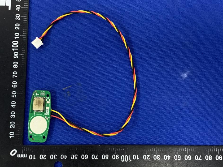
Page 1 of 2 Appendix C: Photographs of EUT Product: Bluetooth module Model: C22K External Photos Antenna Page 2 of 2
Label Artwork and Location Model: C22K Label: Size: L*W= 10*10mm Location
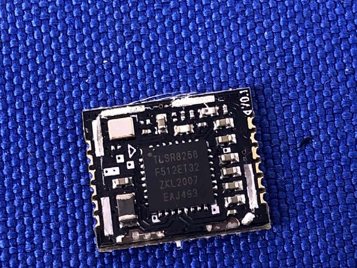
Page 1 of 1 Appendix C: Photographs of EUT Product: Bluetooth module Model: C22K Internal Photos
RF exposure evaluation §2.1093 Radiofrequency radiation exposure evaluation: Portable Devices. According to§15.247(i) and§1.1307b(1), systems operating under the provisions of this section shall be operated in a manner that ensures that the public is not exposed to radio frequency energy level in excess of the commission’s guidance. The 1-g SAR test exclusion thresholds for 100 MHz to 6 GHz at test separation distances ≤ 50 mm are determined by: [(max. power of channel, including tune-up tolerance, mW) / (min. test separation distance, mm)] · [√f(GHz)] ≤ 3.0 for 1-g SAR, where f(GHz) is the RF channel transmit frequency in GHz Power and distance are rounded to the nearest mW and mm before calculation When the minimum test separation distance is < 5 mm, a distance of 5 mm according is applied to determine SAR test exclusion. The result is rounded to one decimal place for comparison For BLE(1M): Channel Frequency (GHz) Max. Power (dBm) Tune up Power (dBm) Max. Tune up Power (dBm) Max. Tune up Power (mW) Test distance (mm) Result exclusion thresholds for 1-g SAR CH 19 2.440 6.20 5.5±1 6.5 4.47 5 1.40 3.0 For BLE(2M): Channel Frequency (GHz) Max. Power (dBm) Tune up Power (dBm) Max. Tune up Power (dBm) Max. Tune up Power (mW) Test distance (mm) Result exclusion thresholds for 1-g SAR CH 00 2.402 6.09 5.5±1 6.5 4.47 5 1.39 3.0 Result: Base on the calculation value, No SAR measurement is required.
Hotline: 400-6611-140 Tel: 86-755-27673339 Fax: 86-755-27673332 http://www.tct-lab.com TEST REPORT FCC ID: 2AQ95-C22K Product: Bluetooth module Model No.: C22K Additional Model No.: N/A Trade Mark: NIU Report No.: TCT210125E001 Issued Date: Feb. 08, 2021 Issued for: Beijing Niu Technology Co., Ltd Block A, 11F, No.10 Wangjing street, Chaoyang, Beijing, 100102 China Issued By: Shenzhen Tongce Testing Lab. 1B/F., Building 1, Yibaolai Industrial Park, Qiaotou, Fuyong, Baoan District, Shenzhen, Guangdong, China TEL: +86-755-27673339 FAX: +86-755-27673332 Note: This report shall not be reproduced except in full, without the written approval of Shenzhen Tongce Testing Lab. This document may be altered or revised by Shenzhen Tongce Testing Lab. personnel only, and shall be noted in the revision section of the document. The test results in the report only apply to the tested sample. Report No.: TCT210125E001 Page 2 of 61 Hotline: 400-6611-140 Tel: 86-755-27673339 Fax: 86-755-27673332 http://www.tct-lab.com TABLE OF CONTENTS 1. Test Certification ..................................................................................... 3 2. Test Result Summary .............................................................................. 4 3. EUT Description ....................................................................................... 5 4. General Information ................................................................................. 6 4.1. Test environment and mode ................................................................................. 6 4.2. Description of Support Units ................................................................................ 6 5. Facilities and Accreditations .................................................................. 7 5.1. Facilities ................................................................................................................. 7 5.2. Location ................................................................................................................. 7 5.3. Measurement Uncertainty ..................................................................................... 7 6. Test Results and Measurement Data ..................................................... 8 6.1. Antenna requirement ............................................................................................ 8 6.2. Conducted Emission ............................................................................................. 9 6.3. Conducted Output Power ................................................................................... 13 6.4. Emission Bandwidth ........................................................................................... 14 6.5. Power Spectral Density ....................................................................................... 15 6.6. Conducted Band Edge and Spurious Emission Measurement ....................... 16 6.7. Radiated Spurious Emission Measurement ...................................................... 18 Appendix A: Test Result of Conducted Test Appendix B: Photographs of Test Setup Appendix C: Photographs of EUT Report No.: TCT210125E001 Page 3 of 61 Hotline: 400-6611-140 Tel: 86-755-27673339 Fax: 86-755-27673332 http://www.tct-lab.com 1. Test Certification Product: Bluetooth module Model No.: C22K Additional Model No.: N/A Trade Mark: NIU Applicant: Beijing Niu Technology Co., Ltd Address: Block A, 11F, No.10 Wangjing street, Chaoyang, Beijing, 100102 China Manufacturer: Changzhou Wujin Blector Electronic Co., Ltd. Address: 19 Mahang South Road, Wujin National High And New Tech Development Zone, Changzhou City, Jiangsu, China Date of Test: Jan. 26, 2021 – Feb. 08, 2021 Applicable Standards: FCC CFR Title 47 Part 15 Subpart C Section 15.247 FCC KDB 558074 D01 15.247 Meas Guidance v05r02 ANSI C63.10:2013 The above equipment has been tested by Shenzhen Tongce Testing Lab. and found compliance with the requirements set forth in the technical standards mentioned above. The results of testing in this report apply only to the product/system, which was tested. Other similar equipment will not necessarily produce the same results due to production tolerance and measurement uncertainties. Tested By: Date: Feb. 08, 2021 Kevin Huang Reviewed By: Date: Feb. 08, 2021 Beryl Zhao Approved By: Date: Feb. 08, 2021 Tomsin Report No.: TCT210125E001 Page 4 of 61 Hotline: 400-6611-140 Tel: 86-755-27673339 Fax: 86-755-27673332 http://www.tct-lab.com 2. Test Result Summary Requirement CFR 47 Section Result Antenna requirement §15.203/§15.247 (c) PASS AC Power Line Conducted Emission §15.207 PASS Conducted Peak Output Power §15.247 (b)(3) PASS 6dB Emission Bandwidth §15.247 (a)(2) PASS Power Spectral Density §15.247 (e) PASS Band Edge §15.247(d) PASS Spurious Emission §15.205/§15.209 PASS Note: 1. PASS: Test item meets the requirement. 2. Fail: Test item does not meet the requirement. 3. N/A: Test case does not apply to the test object. 4. The test result judgment is decided by the limit of test standard. 5. After pre-testing the two earphones, the two earphones are left and right ears respectively; we found that the left earphone is the worst case, so the results are recorded in this report. Report No.: TCT210125E001 Page 5 of 61 Hotline: 400-6611-140 Tel: 86-755-27673339 Fax: 86-755-27673332 http://www.tct-lab.com 3. EUT Description Product: Bluetooth module Model No.: C22K Additional Model No.: N/A Trade Mark: NIU Bluetooth Version: V5.0 Operation Frequency: 2402MHz~2480MHz Channel Separation: 2MHz Data Rate: LE 1M PHY, LE 2M PHY Number of Channel: 40 Modulation Type: GFSK Antenna Type: PCB Antenna Antenna Gain: -1dBi Power Supply: DC 3V Note: The antenna gain listed in this report is provided by applicant, and the test laboratory is not responsible for this parameter. Operation Frequency each of channel Channel Frequency Channel Frequency Channel Frequency Channel Frequency 0 2402MHz 10 2422MHz 20 2442MHz 30 2462MHz …
Text truncated - open the document above for the full version.
Page 1 of 2 Appendix B: Photographs of Test Setup Product: Bluetooth module Model: C22K Radiated Emission Page 2 of 2 Conducted Emission
| # | Rule Parts | Frequency Range | Power Output |
|---|---|---|---|
| 1 | 15C | 2.40 GHz - 2.48 GHz | 4.20 mW |

Bluetooth module
Equipment Class
DTS - Digital Transmission System