2AQ9VN3XVMUuVision Remote Console
Shanghai United Imaging Healthcare Co., Ltd.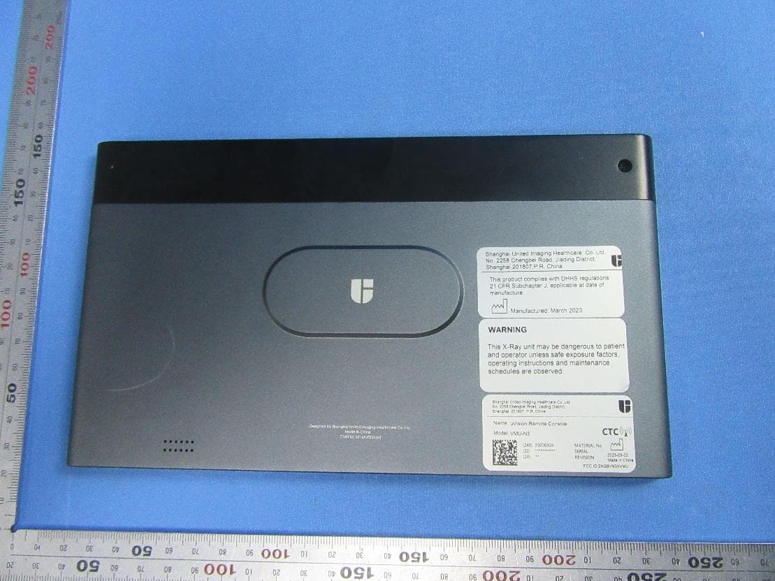
Click to zoom
Application Details
- Equipment Class
- DTS - Digital Transmission System
- Date of Grant
- Apr 17, 2023
- Application Purpose
- Original Equipment
- Date of Application
- Mar 28, 2023
- Equipment Note
- uVision Remote Console
- Frequency Range
- 2412.00000000 - 2462.00000000
- Country
- China
Documents & Files
Document Text
Text extracted from the exhibit documents filed with the FCC. Open a document above to read the original.
Users Manual
Shanghai United Imaging Healthcare Co., Ltd. All rights reserved. Page 1 of 5 uVision Remote Console User Manual Foreword This manual provides instructions on the functions, operation methods, and daily maintenance methods of uVision Remote Console. Applicable products This manual applies to the following products: Product name Product model Software version uVision Remote Console VMU-N3 R001 Audience UIH training and customer service engineers. UIH marketing personnel. Authorized distributors of UIH. Contact information In case of any problem, please contact UIH Service Center. Shanghai United Imaging Healthcare Co., Ltd. Telephone: 0086 400-686-6088 E-mail: [email protected] Website: www.united-imaging.com Address: 2258 Chengbei Rd., Jiading District, Shanghai, 201807 Shanghai United Imaging Healthcare Co., Ltd. All rights reserved. Page 2 of 5 1. Introduction In order to protect the operators from the radiation, we develop two methods to carry remote exposure. They are the Remote Control Unit and uVision Remote Console. The collimator light and exposure can be controlled remotely. The workflow can be synchronized through the uVision Remote Console. Remote exposure could be performed while watching patients’ video. It brings users a safer and more efficient exposure experience. The uVision Remote Console should be placed on the collimator for charging. The suction between them is strong and it will not fall down even if the device moves at the maximum speed. The uVision Remote Console is a component of the Mobile Digital Medical X-ray Imaging System for indoor use. Mobile Digital Medical X-ray Imaging System is usually used in the examination room or ward. Mobile Digital Medical X-ray Imaging System provides 12V DC power supply for uVision Remote Console with PogoPin charging connector. 2. Components of uVision Remote Console Figure 1 uVision Remote Console No. Component Description 1 Collimator lights button Switching on or off the light localizer/linear laser localizer. 2 Exposure button Triggering exposure. 3 Power button Switching the uVision on or off. 4 uVision indicator Purple: Successful uVision pairing White: Communication established Green: Exposure preparation Yellow: Exposure started 5 uVision screen A touchscreen. It is used to display equipment state and system software interface. 6 uVision charging port Used to charge the uVision when the uVision is placed in the uVision hold. Shanghai United Imaging Healthcare Co., Ltd. All rights reserved. Page 3 of 5 3. System Power Supply The internal battery can provide 7.7V DC power to the uVision Remote Console. At the same time, an external PogoPin charging connector can provide 12V DC power to the uVision Remote Console. When the user holds the VMU, the charging interface definition from left to right is shown in the following figure. Figure 2 Charging interface definition 4. Switching the uVision Remote Console on or off 4.1 Switching the uVision Remote Console on Hold down the power button on the uVision for 3 s. The startup process takes less than 30 s. Enter the 4-digit password to log on. 4.2 Switching the uVision Remote Console off Hold down the power button on the uVision for 3 s. Click the shutdown button, and the VMU will shut down 4.3 Switching the uVision Remote Console off forcibly The uVision can be forcibly switched off when the uVision software does not respond. Hold down the power button on the uVision for 6 s. 5. Connecting the uVision Remote Console The uVision Remote Console is connected to the equipment through Wi-Fi. If the uVision cannot be connected to the Wi-Fi, contact UIH Customer Service Center. In factory, the uVision has been paired to the system through Wi-Fi. The uVision will automatically connect to the equipment once it detects the Wi-Fi network of the equipment. 6. System status monitoring When the uVision Remote Console is placed in uVision Remote Console holder, you can monitor the system status (motorized motion state, positioning state, and stand-by state via the uVision Remote Console). Shanghai United Imaging Healthcare Co., Ltd. All rights reserved. Page 4 of 5 7. Remote exposure You can start the X-ray exposure when the OK ring in the System Status area is green. During remote exposure, no operation can be performed in the uVision interface. 1) Press the exposure button on the uVision Remote Console. When the uVision Remote Console indicator turns white, release the exposure button. 2) Hold down the exposure button for the second time within 2 s. The uVision Remote Console indicator turns green. At the beginning of and during exposure, the uVision Remote Console indicator is yellow and an expo- sure prompt tone is played. 3) After you hear the exposure prompt tone and see that the uVision Remote Console indicator is off, release the exposure button. The exposure is completed. 4) The exposure will be stopped if any button is released midway. 8. Video monitoring In the Exam interface, you can monitor the patient's position in real time by Wi-Fi Module. The radiation pre-warning bar displays the distance from the uVision remote console to the equipment. Red indicates the hazardous area and green indicates the safe area. Figure 3 Video monitoring interface of the uVision remote console 9. uVision Remote Console Settings Click the settings button in the upper right corner of the uVision remote console to open the uVision remote console setting interface. 1) You can adjust the sleep time of the uVision and set the automatic screen-off time to any of the following values: 30s、1mins、2mins、5mins、never。 2) You can set SSID and PSK in the Wifi settings interface to connect the AP of mobile DR. 3) You can adjust the screen brightness or turn on the automatic brightness adjustment function. Shanghai United Imaging Healthcare Co., Ltd. All rights reserved. Page 5 of 5 10. FCC Conformity Statement Please take attention that changes or modification not expressly approved by the p…
Text truncated - open the document above for the full version.
Attestation Statements
Shanghai United Imaging Healthcare Co., Ltd. Date: 2023-03-22 Declaration Letter about Limited Use To whom it may concern, WE (Shanghai United Imaging Healthcare Co., Ltd.) HEREBY DECLARED THAT Our product Product Description: uVision Remote Console Model No: VMU-N3 FCC ID: 2AQ9VN3XVMU The WiFi Module AP6356S has two antenna ports , However, the export to the U.S. market ,only one antenna port 0 is opened , other antenna port 1 is disabled. Any problems caused by such restrictions shall be borne by our company. Name (Printed): XIN GAO Signature: Title: RA Manager On behalf of Company: Shanghai United Imaging Healthcare Co., Ltd. Telephone: +86(21)67076888
Cover Letter(s)
Shanghai United Imaging Healthcare Co., Ltd Tel: +86 (21) 67076888 Fax: +86 (21) 67076889 www.umted-ima1cj胆com To: SGS North America Inc 620 Old Peachtree Road SUITE 100 Suwanee, Geo「gia United States From: Shanghai United Imaging Healthcare Co., Ltd 2258 Chengbei Rd., Jiading District, Shanghai, China , 201807 UNITED IM.1\6血i ,� Regarding Confidentiality Request regarding application for FCC ID 2AQ9VN3XVMU LONG TERM CONFIDENTIALITY Pursuant to 47 CFR Section 0.459 and 0.457 of the commission's rules, the applicant hereby request confidential treatment of the documents listed below, associated with the cert巾cation application referenced above Schematic(s) Block Diag「ams Operational Descriptions The documents above contain proprietary information not released to the public. Public disclosu「e of this information may prove harmful to the business of the applicant. Sincerely , XIN GAO RA Manager 心.,....G妇 Shanghai United Imaging Healthcare Co., Ltd N II Software Security Info Tune Up
External Photos
SGS-CSTC Standards Technical Services (Shanghai) Co., Ltd. Page: 1 of 4 External Photos for SHCR2303000457ME SGS-CSTC Standards Technical Services (Shanghai) Co., Ltd. Page: 2 of 4 EUT Constructional Details (EUT Photos) SGS-CSTC Standards Technical Services (Shanghai) Co., Ltd. Page: 3 of 4 SGS-CSTC Standards Technical Services (Shanghai) Co., Ltd. Page: 4 of 4
ID Label/Location Info
Shanghai United Imaging Healthcare Co., Ltd. Tel: +86 (21) 67076888 Fax:+86 (21) 67076889 www.united-imaging.com 1.Equipment Label Template Shanghai United Imaging Healthcare Co., Ltd. Tel: +86 (21) 67076888 Fax:+86 (21) 67076889 www.united-imaging.com 2.Label Location
Internal Photos
SGS-CSTC Standards Technical Services (Shanghai) Co., Ltd. Page: 1 of 10 Internal Photos for SHCR2303000457ME SGS-CSTC Standards Technical Services (Shanghai) Co., Ltd. Page: 2 of 10 EUT Constructional Details (EUT Photos) SGS-CSTC Standards Technical Services (Shanghai) Co., Ltd. Page: 3 of 10 SGS-CSTC Standards Technical Services (Shanghai) Co., Ltd. Page: 4 of 10 SGS-CSTC Standards Technical Services (Shanghai) Co., Ltd. Page: 5 of 10 SGS-CSTC Standards Technical Services (Shanghai) Co., Ltd. Page: 6 of 10 SGS-CSTC Standards Technical Services (Shanghai) Co., Ltd. Page: 7 of 10 SGS-CSTC Standards Technical Services (Shanghai) Co., Ltd. Page: 8 of 10 SGS-CSTC Standards Technical Services (Shanghai) Co., Ltd. Page: 9 of 10 SGS-CSTC Standards Technical Services (Shanghai) Co., Ltd. Page: 10 of 10
RF Exposure Info
Compliance Certification Services (Kunshan) Inc. Page: 1 of 6 Appendix D for KSCR230300045401 Photographs 1. SAR measurement System 2. Photographs of Tissue Simulate Liquid 3. Photographs of EUT test position 4. EUT Antenna Locations 5. EUT Constructional Details Compliance Certification Services (Kunshan) Inc. Page: 2 of 6 1. SAR measurement System Compliance Certification Services (Kunshan) Inc. Page: 3 of 6 2. Photographs of Tissue Simulate Liquid Tissue Simulant Liquid for Head 2450 Tissue Simulant Liquid for Head 5GHz Compliance Certification Services (Kunshan) Inc. Page: 4 of 6 3. Photographs of EUT test position Back Side Edge 1 Edge 2 Edge 3 Edge 4 Compliance Certification Services (Kunshan) Inc. Page: 5 of 6 4. EUT Antenna Locations Compliance Certification Services (Kunshan) Inc. Page: 6 of 6 5. EUT Constructional Details Details please Refer to Appendix – Photographs of EUT Constructional Details for FYCR2211000474AT.
RF Exposure Info
Compliance Certification Services (Kunshan) Inc. Page: 1 of 25 Appendix C for KSCR230300045401 Calibration Certificate Object Apply No Model SN Calibration Date Due date of calibration Dipole 1 CLA150 4025 2021/04/26 2024/04/25 2 D450V3 1103 2021/04/21 2024/04/20 3 D750V3 1188 2022/03/29 2025/03/28 4 D835V2 4d114 2022/03/31 2025/03/30 5 D900V2 1d079 2022/06/07 2025/06/06 6 D1800V2 2d170 2022/03/31 2025/03/30 7 D1900V2 5d136 2022/06/07 2025/06/06 8 D2000V2 1041 2022/06/06 2025/06/05 9 D2300V2 1096 2022/03/31 2025/03/30 10 D2450V2 817 2022/04/01 2025/03/31 11 D2600V2 1158 2022/03/31 2025/03/30 12 D5GHzV2 1095 2022/06/01 2025/05/31 DAE 13 DAE4 1245 2022/05/30 2023/05/29 Probe 14 EX3DV4 7767 2022/10/28 2023/10/27 Compliance Certification Services (Kunshan) Inc. Page: 2 of 25 1 Di pol e 1.1 CLA150 - SN 4025 Compliance Certification Services (Kunshan) Inc. Page: 3 of 25 1.2 D450V3 - SN 1103 Compliance Certification Services (Kunshan) Inc. Page: 4 of 25 Compliance Certification Services (Kunshan) Inc. Page: 5 of 25 1.3 D750V3 - SN 1188 Compliance Certification Services (Kunshan) Inc. Page: 6 of 25 1.4 D835V2 - SN 4d114 Compliance Certification Services (Kunshan) Inc. Page: 7 of 25 Compliance Certification Services (Kunshan) Inc. Page: 8 of 25 1.5 D900V2 - SN 1d079 Compliance Certification Services (Kunshan) Inc. Page: 9 of 25 1.6 D1800V2 - SN 2d170 Compliance Certification Services (Kunshan) Inc. Page: 10 of 25 Compliance Certification Services (Kunshan) Inc. Page: 11 of 25 1.7 D1900V2 - SN 5d136 Compliance Certification Services (Kunshan) Inc. Page: 12 of 25 1.8 D2000V2 - SN 1041 Compliance Certification Services (Kunshan) Inc. Page: 13 of 25 Compliance Certification Services (Kunshan) Inc. Page: 14 of 25 1.9 D2300V2 - SN 1096 Compliance Certification Services (Kunshan) Inc. Page: 15 of 25 1.10 D2450V2 - SN 817 Compliance Certification Services (Kunshan) Inc. Page: 16 of 25 Compliance Certification Services (Kunshan) Inc. Page: 17 of 25 1.11 D2600V2 - SN 1158 Compliance Certification Services (Kunshan) Inc. Page: 18 of 25 1.12 D5GHzV2 - SN 1095 Compliance Certification Services (Kunshan) Inc. Page: 19 of 25 Compliance Certification Services (Kunshan) Inc. Page: 20 of 25 Compliance Certification Services (Kunshan) Inc. Page: 21 of 25 2 DA E4 - SN 1245 Compliance Certification Services (Kunshan) Inc. Page: 22 of 25 3 EX3DV4 - SN 7767 Compliance Certification Services (Kunshan) Inc. Page: 23 of 25 Compliance Certification Services (Kunshan) Inc. Page: 24 of 25 Compliance Certification Services (Kunshan) Inc. Page: 25 of 25 4 I m pedance and ret ur n l oss Dipole CLA150 SN 4025 Head Liquid Date of Measurement Return Loss(dB) Δ % Impedance (Ω) ΔΩ 2021/4/26 -31.4 / 47.8 / 2022/4/26 -32.5 -3.5% 47.1 -0.7 Dipole D450V3 SN 1103 Head Liquid Date of Measurement Return Loss(dB) Δ % Impedance (Ω) ΔΩ 2021/4/21 -23 / 57.1 / 2022/4/26 -23.4 -1.74% 56.6 -0.5
Test Report
SGS-CSTC Standards Technical Services (Shanghai) Co., Ltd. Report No.: SHCR230300045702 Page: 1 of 104 Parlam Zhan Laboratory Manager TEST REPORT Application No.: SHCR2303000457ME FCC ID: 2AQ9VN3XVMU Applicant: Shanghai United Imaging Healthcare Co., Ltd. Address of Applicant: 2258 Chengbei Rd., Jiading District, Shanghai Manufacturer: Shanghai United Imaging Healthcare Co., Ltd. Address of Manufacturer: 2258 Chengbei Rd., Jiading District, Shanghai Factory: SHENZHEN KTC MEDICAL SOLUTIONS CO., LTD. Address of Factory: No.4023 Wuhe Road, Bantian Subdistrict, Longgang District, Shenzhen Equipment Under Test (EUT): EUT Name: uVision Remote Console Model No.: VMU-N3 Standard(s) : 47 CFR Part 15, Subpart C 15.247 Date of Receipt: 2023-03-07 Date of Test: 2023-03-09 to 2023-03-13 Date of Issue: 2023-03-14 Test Result: Pass* * In the configuration tested, the EUT complied with the standards specified above. SGS-CSTC Standards Technical Services (Shanghai) Co., Ltd. Report No.: SHCR230300045702 Page: 2 of 104 Revision Record Version Description Date Remark 00 Original 2023-03-14 / Authorized for issue by: Bill Wu/Project Engineer Parlam Zhan/Reviewer SGS-CSTC Standards Technical Services (Shanghai) Co., Ltd. Report No.: SHCR230300045702 Page: 3 of 104 2 Test Summary Radio Spectrum Technical Requirement Item Standard Method Requirement Result Antenna Requirement 47 CFR Part 15, Subpart C 15.247 N/A 47 CFR Part 15, Subpart C 15.203 & 15.247(b)(4) Pass Radio Spectrum Matter Part Item Standard Method Requirement Result Conducted Average Output Power 47 CFR Part 15, Subpart C 15.247 ANSI C63.10 (2013) Section 11.9.2 47 CFR Part 15, Subpart C 15.247(b)(3) Pass Minimum 6dB Bandwidth ANSI C63.10 (2013) Section 11.8.1 47 CFR Part 15, Subpart C 15.247a(2) Pass Power Spectrum Density ANSI C63.10 (2013) Section 11.10.3 47 CFR Part 15, Subpart C 15.247(e) Pass Conducted Band Edges Measurement ANSI C63.10 (2013) Section 11.13.3.2 47 CFR Part 15, Subpart C 15.247(d) Pass Conducted Spurious Emissions ANSI C63.10 (2013) Section 11.11 47 CFR Part 15, Subpart C 15.247(d) Pass Radiated Emissions which fall in the restricted bands ANSI C63.10 (2013) Section 6.10.5 47 CFR Part 15, Subpart C 15.205 & 15.209 Pass Radiated Spurious Emissions Below 1GHz ANSI C63.10 (2013) Section 6.4,6.5 47 CFR Part 15, Subpart C 15.205 & 15.209 Pass Radiated Spurious Emissions Above 1GHz ANSI C63.10 (2013) Section 6.6 47 CFR Part 15, Subpart C 15.205 & 15.209 Pass SGS-CSTC Standards Technical Services (Shanghai) Co., Ltd. Report No.: SHCR230300045702 Page: 4 of 104 3 Contents Page 1 COVER PAGE ............................................................................................................................................ 1 2 TEST SUMMARY ....................................................................................................................................... 3 3 CONTENTS ................................................................................................................................................ 4 4 GENERAL INFORMATION ........................................................................................................................ 6 4.1 DETAILS OF E.U.T. ............................................................................................................................... 6 4.2 DESCRIPTION OF SUPPORT UNITS ......................................................................................................... 6 4.3 POWER LEVEL SETTING USING IN TEST: .................................................................................................. 6 4.4 MEASUREMENT UNCERTAINTY & DECISION RULE ................................................................................... 6 4.5 TEST LOCATION .................................................................................................................................... 7 4.6 TEST FACILITY ...................................................................................................................................... 7 4.7 DEVIATION FROM STANDARDS ............................................................................................................... 7 4.8 ABNORMALITIES FROM STANDARD CONDITIONS ..................................................................................... 7 5 EQUIPMENT LIST ...................................................................................................................................... 8 6 RADIO SPECTRUM TECHNICAL REQUIREMENT ................................................................................. 9 6.1 ANTENNA REQUIREMENT ...................................................................................................................... 9 6.1.1 Test Requirement: ......................................................................................................................... 9 6.1.2 Conclusion ..................................................................................................................................... 9 7 RADIO SPECTRUM MATTER TEST RESULTS ..................................................................................... 10 7.1 CONDUCTED AVERAGE OUTPUT POWER .............................................................................................. 10 7.1.1 E.U.T. Operation .......................................................................................................................... 10 7.1.2 Test Mode Description ................................................................................................................. 10 7.1.3 Test Setup Diagram ..................................................................................................................... 11 7.1.4 Measurement Procedure and Data............................................................................................. 11 7.2 MINIMUM 6DB BANDWIDTH ....................................................................................…
Text truncated - open the document above for the full version.
Test Report
Shanghai Hongluo Communication Electronics Co., Ltd 1 IO01HL0260-3101 WiFi FPC Antenna Product Specification Shanghai Hongluo Communication Electronics Co., Ltd 2 Contents 1. Structural Drawings ......................................................................................................................... 3 2. Performance Parameter Table ..................................................................................................... 4 3. Test Data ............................................................................................................................................. 4 Shanghai Hongluo Communication Electronics Co., Ltd 3 1. Structural Drawings Unit:mm Figure 1 Antenna Outline Dimension Shanghai Hongluo Communication Electronics Co., Ltd 4 2. Performance Parameter Table Project Parameter Item Parameter Index Explain Electrical Performance Requirements Frequency Range 2400~2480MHz 5150~5850MHz Test conditions Test with Equipment Tooling Gain 1dBi Max,with Cable Standing Wave Ratio ≤3:1@2400~2480MHz ≤4:1@5150~5850MHz with Cable Structural Appearance Requirements Antenna Body Size Refer to Structure Drawing Interface processing method Φ1.13mm cable+ IPX Color Black Environmental Adaptability Requirements Storage Temperature -20~+40°C Salt Mist 24H Environment Protection RoHS Bending ≥10 3. Test Data 3.1 Efficiency and Gain Frequency(MHz) Efficiency(%) Gain(dBi) 2400 84.7 0.30 2410 82.0 1.00 2420 80.7 0.90 2430 82.4 1.00 2440 85.2 0.85 2450 86.0 0.88 2460 90.2 0.79 2470 91.6 0.81 2480 90.6 0.91 2490 90.0 0.85 2500 91.5 0.67 Shanghai Hongluo Communication Electronics Co., Ltd 5 Frequency(MHz) Efficiency(%) Gain(dBi) 5150 64.25 0.71 5200 57.36 0.77 5250 59.48 0.67 5300 62.30 0.81 5350 61.72 0.65 5400 67.59 0.66 5450 63.91 0.71 5500 62.87 0.67 5550 56.15 0.78 5600 67.53 0.84 5650 68.89 0.76 5700 68.68 0.77 5750 72.92 0.81 5800 73.78 0.82 5850 74.01 0.69 3.2 Directional Pattern 2400-2500MHz Phi=0° Phi=90° Theta=90° 3D Pattern Shanghai Hongluo Communication Electronics Co., Ltd 6 5150-5850MHz
Test Setup Photos
SGS-CSTC Standards Technical Services (Shanghai) Co., Ltd. Page: 1 of 3 Appendix Photographs of Test Setup for SHCR2303000457ME Test Model No.: VMU-N3 SGS-CSTC Standards Technical Services (Shanghai) Co., Ltd. Page: 2 of 3 Test Setup Photo Radiated Emissions below 1GHz Radiated Emissions above 1GHz SGS-CSTC Standards Technical Services (Shanghai) Co., Ltd. Page: 3 of 3 The EUT Details of Zoom RF Conducted
Contact Information
Applicant
Xin GAO
Technical Contact
SGS-CSTC Standards Technical Services Co., Ltd.Parlam Zhan
[email protected]+862161915666
588 West Jindu Road, Xinqiao, Songjiang · ShangHai · China
Non-Technical Contact
SGS-CSTC Standards Technical Services Co., Ltd.Parlam Zhan
[email protected]+862161915666
Test Firm
SGS-CSTC Standards Technical Services Co., Ltd.Parlam Zhan
[email protected]13636390700
Technical Specifications
| # | Rule Parts | Frequency Range | Power Output |
|---|---|---|---|
| 1 | 15C | 2.41 GHz - 2.46 GHz | 14.00 mW |
Other Applications from Shanghai United Imaging Healthcare Co., Ltd.
2AQ9V-MS88SFA
Nov 27, 2025COU64-VSMR
Equipment Class
DTS - Digital Transmission System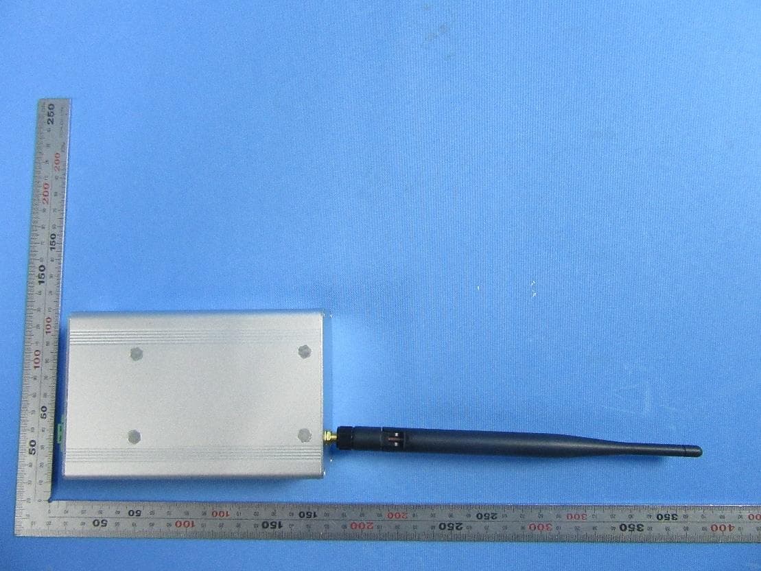
2AQ9VN3XUWB
Apr 13, 2023UWB Gateway
Equipment Class
UWB - Ultra Wideband Transmitter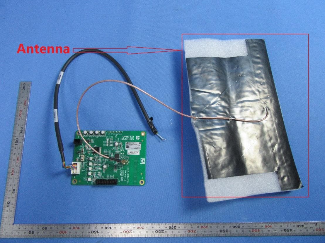
2AQ9VN3XRCU-R
Mar 23, 2023NeZha3 Remote Control Board
Equipment Class
DSC - Part 15 Security/Remote Control Transmitter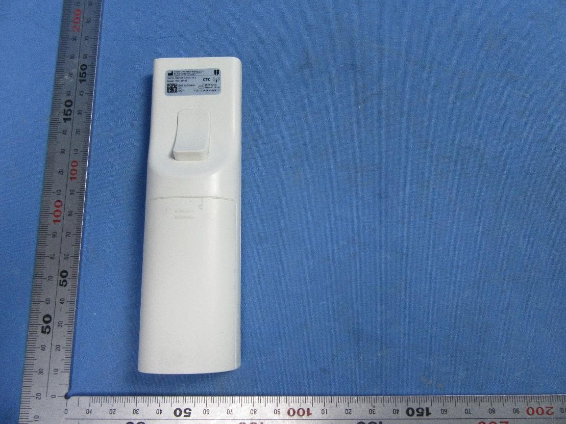
2AQ9VN3XRCU
Mar 23, 2023Remote Control Unit
Equipment Class
DSC - Part 15 Security/Remote Control Transmitter