2AQJL-DX2002Wireless module
Shenzhen Liangming Technology Co., Ltd.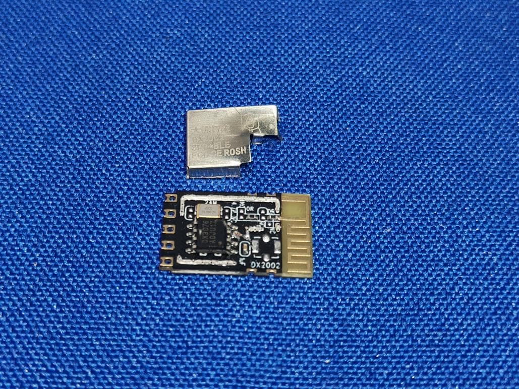
Click to zoom
Application Details
- Equipment Class
- DTS - Digital Transmission System
- Date of Grant
- Apr 18, 2022
- Application Purpose
- Original Equipment
- Date of Application
- Apr 18, 2022
- Equipment Note
- Wireless module
- Frequency Range
- 2402.00000000 - 2480.00000000
- Country
- China
Documents & Files
Document Text
Text extracted from the exhibit documents filed with the FCC. Open a document above to read the original.
Attestation Statements
Shenzhen Liangming Technology Co., Ltd. Statement We Shenzhen Liangming Technology Co., Ltd. Hereby Declare that The product Wireless module, models no. DX2002, DX2002A, DX2002B are all identical in interior structure, electrical circuits and components, and just the model names are different for the marketing requirement. Your assistance on this matter is highly appreciated. Yours sincerely, Signature: <Signature>: Name:Zhibin Lv Title:Manager
Cover Letter(s)
Compliance list INTEGRATION INSTRUCTIONS for 996369 D03 OEM the and 996369 D03 OEM by Sections 2.2 through 2.10. Requirement Yes N/A Comment 2.2 List of applicable FCC rules List the FCC rules that are applicable to the modular transmitter. These are the rules that specifically establish the bands of operation, the power, spurious emissions, and operating fundamental frequencies. DO NOT list compliance to unintentional-radiator rules (Part 15 Subpart B) since that is not a condition of a module grant that is extended to a host manufacturer. See also Section 2.10 below concerning the need to notify host manufacturers that further testing is required.3 YES Refer to instruction FCC standards: FCC CFR Title 47 Part 15 Subpart C Section 15.247 2.3 Summarize the specific operational use conditions Describe use conditions that are applicable to the modular transmitter, including for example any limits on antennas, etc. For example, if point-to-point antennas are used that require reduction in power or compensation for cable loss, then this information must be in the instructions. If the use condition limitations extend to professional users, then instructions must state that this information also extends to the host manufacturer’s instruction manual. In addition, certain information may also be needed, such as peak gain per frequency band and minimum gain, specifically for master devices in 5 GHz DFS bands. YES Refer to instruction PCB antenna with antenna gain 2.0dBi or integral antenna (Male IPEX connector ) with antenna gain 0.8dBi 2.4 Limited module procedures If a modular transmitter is approved as a “limited module,” then the module manufacturer is responsible for approving the host environment that the limited module is used with. The manufacturer of a limited module must describe, both in the filing and in the installation instructions, the alternative means that the limited module manufacturer uses to verify that the host meets the necessary requirements to satisfy the module limiting conditions. A limited module manufacturer has the flexibility to define its alternative method to address the conditions that limit the initial approval, such as: shielding, minimum N/A Not applicable signaling amplitude, buffered modulation/data inputs, or power supply regulation. The alternative method could include that the limited module manufacturer reviews detailed test data or host designs prior to giving the host manufacturer approval. This limited module procedure is also applicable for RF exposure evaluation when it is necessary to demonstrate compliance in a specific host. The module manufacturer must state how control of the product into which the modular transmitter will be installed will be maintained such that full compliance of the product is always ensured. For additional hosts other than the specific host originally granted with a limited module, a Class II permissive change is required on the module grant to register the additional host as a specific host also approved with the module. 2.5 Trace antenna designs For a modular transmitter with trace antenna designs, see the guidance in Question 11 of KDB Publication 996369 D02 FAQ – Modules for Micro-Strip Antennas and traces. The integration information shall include for the TCB review the integration instructions for the following aspects: layout of trace design, parts list (BOM), antenna, connectors, and isolation requirements.4 a) Information that includes permitted variances (e.g., trace boundary limits, thickness, length, width, shape(s), dielectric constant, and impedance as applicable for each type of antenna); b) Each design shall be considered a different type (e.g., antenna length in multiple(s) of frequency, the wavelength, and antenna shape (traces in phase) can affect antenna gain and must be considered); c) The parameters shall be provided in a manner permitting host manufacturers to design the printed circuit (PC) board layout; d) Appropriate parts by manufacturer and specifications; e) Test procedures for design verification; and f) Production test procedures for ensuring N/A Not applicable compliance. The module grantee shall provide a notice that any deviation(s) from the defined parameters of the antenna trace, as described by the instructions, require that the host product manufacturer must notify the module grantee that they wish to change the antenna trace design. In this case, a Class II permissive change application is required to be filed by the grantee, or the host manufacturer can take responsibility through the change in FCC ID (new application) procedure followed by a Class II permissive change application. 2.6 RF exposure considerations It is essential for module grantees to clearly and explicitly state the RF exposure conditions that permit a host product manufacturer to use the module. Two types of instructions are required for RF exposure information: (1) to the host product manufacturer, to define the application conditions (mobile, portable – xx cm from a person’s body); and (2) additional text needed for the host product manufacturer to provide to end users in their end-product manuals. If RF exposure statements and use conditions are not provided, then the host product manufacturer is required to take responsibility of the module through a change in FCC ID (new application). YES Refer to instruction This modular complies with FCC RF radiation exposure limits set forth for an uncontrolled environment. This transmitter must not be co-located or operating in conjunction with any other antenna or transmitter. 2.7 Antennas A list of antennas included in the application for certification must be provided in the instructions. For modular transmitters approved as limited modules, all applicable professional installer instructions must be included as part of the information to the host product manufacturer. The antenna list shall also identify the antenna types (monopole, PIFA, dipole, etc. (note that for exam…
Text truncated - open the document above for the full version.
Cover Letter(s)
Single Modular approval Declaration letter We ,Shenzhen Liangming Technology Co., Ltd. Apply single modular approval for Product Name: Wireless module Model: DX2002, DX2002A, DX2002B FCC ID: 2AQJL-DX2002 According to 996369 D01 Module Equip Auth Guide v01r04 and 15.212 requirement: 1 )The radio elements must have the radio frequency circuitry shielded. Physical co mponents and tuning capacitor(s) may be located external to the shield, but must be on the module assembly; Answer :Yes; Shielded. 2)The module must have buffered modulation/data inputs to ensure that the device will comply with Part 15 requirements with any type of input signal; Answer :Yes ;All inputs to the modules are buffered through logic or microprocessor inputs. 3)The modular transmitter must have its own power supply regulation. Answer :Yes ;A low drop out regulator is used for modular power supply regulation. 4 )The module must contain a permanently attached antenna, or contain a unique a ntenna connector, and be marketed and operated only with specific antenna(s), per Sections15.203, 15.204(b), 15.204(c), 15.212(a), 2.929(b); Answer :Yes ;Device is equipped with PCB Antenna or integral antenna witch Male IPEX connector. (5) The module must demonstrate compliance in a stand-alone configuration; Answer :Ye s;distance between modular and all AEs are bigger than 10cm ,refer to setup photo. (6) The module must be labeled with its permanently affixed FCC ID label, or use an electronic display (See KDB Publication 784748 about labeling requirements); Answer :Yes ;The modular has a permanent fixed label, and below statement was listed in the User Manual; The host device must be labeled to display the FCC ID of the module “Contains FCC ID: 2AQJL-DX2002” (7) The module must comply with all specific rules applicable to the transmitter including all the conditions provided in the integration instructions by the grantee; Answer :Yes ;The module complies with all specific rules applicable to the transmitter including all the conditions provided in the integration instructions by the grantee, Refer to test report and user manual. (8) The module must comply with RF exposure requirements Answer :Yes ;RF exposure evaluation was done according to Section 4.3.1 of 47 CFR 1.1307 and KDB447498 . Refer to RF exposure Reports and modular installation manual Please contact me if you have any further questions. Thanks for your attention. Best Regards, Signature: Date: April 16, 2002 Name: Zhibin Lv Title: Manager Applicant: Shenzhen Liangming Technology Co., Ltd.
ID Label/Location Info
Size: 19*33mm Material: Tagboard Glue: Adhesive sticker Font type: Candara Font color: BLUE Page color: White Dimmer of CE logo: 7.5mm; MIC logo:5mm 2.4G module Model: DX2002 Input:DC3.3V 0.2A FCC ID: 2AQJL-DX2002 Xxxxxxxxx S/N:XXXXXXXX MADE IN CHINA Shenzhen Liangming Technology Co., Ltd. Label location Label location
RF Exposure Info
FCC ID: 2AQJL-DX2002 RF Exposure Applicable Standard According to §1.1307(b)(5), systems operating under the provisions of this section shall be operated in a manner that ensure that the public is not exposed to radio frequency energy level in excess of the Commission’s guideline. This is a Portable device. The Section 4.3.1 and Appendix A of KDB447498 D01 V05 was used as the guidance. Calculation Result (Worse case) GFSK Mode: [(max. power of channel, including tune-up tolerance, mW)/(min. test separation distance, mm)] · [√f(GHz)] =2.69/5 * 1.5498= 0.83 this value is less than 3.0 for 1-g SAR and ≤ 7.5 for 10-g extremity SAR. The SAR measurement is not necessary.
Test Report
Report No.: TW2203195-02E File Reference No.: 2022-03-31 Applicant: Shenzhen Liangming Technology Co., Ltd. Product: Wireless module Model No.: DX2002, DX2002A, DX2002B Trademark: N/A Test Standards: FCC Part 15.247 Test Result: It is herewith confirmed and found to comply with the requirements set up by ANSI C63.10, FCC Part 15.247 for the evaluation of electromagnetic compatibility Approved By Terry Tang Manager Dated: March 31, 2022 Results appearing herein relate only to the sample tested The technical reports is issued errors and omissions exempt and is subject to withdrawal at SHENZHEN TIMEWAY TESTING LABORATORIES Zone C, 1st Floor, Block B, Jun Xiang Da Building, Zhongshan Park Road West, Tong Le Village, Nanshan District, Shenzhen, China Tel (755) 83448688, Fax (755) 83442996, E-Mail:[email protected] Report No.: TW2203195-02E Page 2 of 46 Date: 2022-03-31 The report refers only to the sample tested and does not apply to the bulk. This report is issued in confidence to the client and it will be strictly treated as such by the SHENZHEN TIMEWAY TESTING LABORATORIES. It may not be reproduced rather in its entirety or in part and it may not be used for adverting. The client to whom the report is issued may, however, show or send it . or a certified copy there of prepared by the SHENZHEN TIMEWAY TESTING LABORATORIES. to his customer. Supplier or others persons directly concerned. SHENZHEN TIMEWAY TESTING LABORATORIES. will not, without the consent of the client enter into any discussion of correspondence with any third party concerning the contents of the report. In the event of the improper use of the report. The SHENZHEN TIMEWAY TESTING LABORATORIES. reserves the rights to withdraw it and to adopt any other remedies which may be appropriate. Special Statement: The testing quality ability of our laboratory meet with “Quality Law of People’s Republic of China” Clause 19. The testing quality system of our laboratory meet with ISO/IEC-17025 requirements, which is approved by CNAL. This approval result is accepted by MRA of APLAC. Our test facility is recognized, certified, or accredited by the following organizations: CNAS-LAB Code: L2292 The EMC Laboratory has been assessed and in compliance with CNAS-CL01 accreditation criteria for testing Laboratories (identical to ISO/IEC 17025:2005 General Requirements) for the Competence of testing Laboratories. FCC-Registration No.: 744189 The EMC Laboratory has been registered and fully described in a report filed with the (FCC) Federal Communications commission. The acceptance letter from the FCC is maintained in our files. Registration No.: 744189. Industry Canada (IC) —Registration No.:5205A The EMC Laboratory has been registered by Certification and Engineering Bureau of Industry Canada for radio equipment testing with Registration No.: 5205A. A2LA (Certification Number:5013.01) The EMC Laboratory has been accredited by the American Association for Laboratory Accreditation (A2LA). Certification Number:5013.01 Report No.: TW2203195-02E Page 3 of 46 Date: 2022-03-31 The report refers only to the sample tested and does not apply to the bulk. This report is issued in confidence to the client and it will be strictly treated as such by the SHENZHEN TIMEWAY TESTING LABORATORIES. It may not be reproduced rather in its entirety or in part and it may not be used for adverting. The client to whom the report is issued may, however, show or send it . or a certified copy there of prepared by the SHENZHEN TIMEWAY TESTING LABORATORIES. to his customer. Supplier or others persons directly concerned. SHENZHEN TIMEWAY TESTING LABORATORIES. will not, without the consent of the client enter into any discussion of correspondence with any third party concerning the contents of the report. In the event of the improper use of the report. The SHENZHEN TIMEWAY TESTING LABORATORIES. reserves the rights to withdraw it and to adopt any other remedies which may be appropriate. Test Report Conclusion Content 1.0 General Details ................................................................................................ 4 1.1 Test Lab Details................................................................................................ 4 1.2 Applicant Details.............................................................................................. 4 1.3 Description of EUT ........................................................................................... 4 1.4 Submitted Sample.............................................................................................. 4 1.5 Test Duration................................................................................................... 5 1.6 Test Uncertainty............................................................................................... 5 1.7 Test By.......................................................................................................... 5 2.0 List of Measurement Equipment......................................................................... 6 3.0 Technical Details............................................................................................. 7 3.1 Summary of Test Results..................................................................................... 7 3.2 Test Standards.................................................................................................. 7 4.0 EUT Modification.............................................................................................7 5.0 Power Line Conducted Emission Test...................................................................... 8 5.1 Schematics of the Test........................................................................................ 8 5.2 Test Method and Test Procedure............................................................................ 8 5.3 Configuration of the EUT.................................................................................... 8 5.4 EUT Operating Cond…
Text truncated - open the document above for the full version.
Test Setup Photos
Conducted Emission Test Setup: Radiated Emission Test Setup:
Contact Information
Applicant
Zhibin Lv
Test Firm
Shenzhen Timeway Testing LaboratoriesTerry Tang
[email protected]+86-755-83448688
Technical Specifications
| # | Rule Parts | Frequency Range | Power Output |
|---|---|---|---|
| 1 | 15C | 2.40 GHz - 2.48 GHz | 1.99 mW |
Other Applications from Shenzhen Liangming Technology Co., Ltd.

2AQJL-LM80P2
Jan 10, 2021Wireless module
Equipment Class
DTS - Digital Transmission System