FCCID.CO- FCC ID Database
HomeCompaniesEquipment ClassesSearch

© 2026 FCC ID Database. All rights reserved.

AboutContactData sourced from FCC public records
  1. Home/
  2. Grado Laboratories,inc/
  3. 2AQMIGW10020

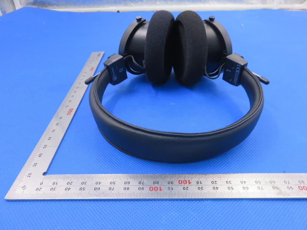
2AQMIGW10020Handband Bluetooth Headphones

Grado Laboratories,inc
Handband Bluetooth Headphones - FCC ID 2AQMIGW10020 - Grado Laboratories,inc
Click to zoom

Application Details

Equipment Class
DSS - Part 15 Spread Spectrum Transmitter
Date of Grant
Jan 14, 2020
Application Purpose
Original Equipment
Date of Application
Jan 14, 2020
Equipment Note
Handband Bluetooth Headphones
Frequency Range
2402.00000000 - 2480.00000000
Company
Grado Laboratories,inc
Country
United States

Documents & Files

Select a file to view
Users Manual

↗

Cover Letter(s)

↗
↗

External Photos

↗

ID Label/Location Info

↗

Internal Photos

↗

RF Exposure Info

↗

Test Report

↗
↗

Test Setup Photos

↗

Document Text

Text extracted from the exhibit documents filed with the FCC. Open a document above to read the original.

Users Manual

Grado GW100 Owner’s Guide C M Y CM MY CY CMY K GW100 Owner's Guide.pdf 1 9/11/18 11:58 AM Handband Bluetooth Headphones Volume Up / Action Volume Down / Action Line-In Charging Light Power / Action Charging Port Mic Overview C M Y CM MY CY CMY K GW100 Owner's Guide.pdf 2 9/11/18 11:58 AM Blue: Fully Charged Blue: Power ed On Red: Charging Red: Low Battery Long Press: Power On / Off Battery Saver:If unpaired for 10 minutes, GW100 will power off . Charging:Plug the USB Type-C cable into the charging port and connect the other end to a compatible USB port of a computer or wall charger. Power C M Y CM MY CY CMY K GW100 Owner's Guide.pdf 3 9/11/18 11:58 AM Long Press:From the off state press and hold until charging light flashes blue and red. On your device, navigate to settings and turn on Bluetooth. After a few seconds, you will see “Grado GW100”. Tap to pair. When the paired device’s Bluetooth is turned off or out of range, the GW100 can connect to a second device. Blue & Red: Ready to Pair Connect C M Y CM MY CY CMY K GW100 Owner's Guide.pdf 4 9/11/18 11:58 AM Short Press: Increase Volume Long Press: Next Song Short Press: Decrease Volume Long Press: Previous Song Short Press: Play / Pause Volume / Music C M Y CM MY CY CMY K GW100 Owner's Guide.pdf 5 9/11/18 11:58 AM Short Press: Increase Volume Short Press: Decrease Volume Double Press: Voice Assistant Short Press: Answer / Hang Up Long Press: Reject Call Phone / Voice C M Y CM MY CY CMY K GW100 Owner's Guide.pdf 6 9/11/18 11:58 AM Working Distance: 10m Bluetooth Version: 5.0 with aptX Battery Life: 50 hours* Charging Time: 2.5 hours Frequency Response: 20Hz~20KHz Mic Sensitivity: 42dB +/- 3dB Battery Capacity: 850mAH Methods of pairing to Bluetooth may vary depending on the specific device. Please refer to the device’s manual for further details. *Battery life will vary depending on the listening volume and genre of music played. Specifications C M Y CM MY CY CMY K GW100 Owner's Guide.pdf 7 9/11/18 11:58 AM C M Y CM MY CY CMY K GW100 Owner's Guide.pdf 8 9/11/18 11:58 AM NOTE: This equipment has been tested and found to comply with the limits for a Class B digital device, pursuant to part 15 of the FCC Rules. These limits are designed to provide reasonable protection against harmful interference in a residential installation. This equipment generates uses and can radiate radio frequency energy and, if not installed and used in accordance with the instructions, may cause harmful interference to radio communications. However, there is no guarantee that interference will not occur in a particular installation. If this equipment does cause harmful interference to radio or television reception, which can be determined by turning the equipment off and on, the user is encouraged to try to correct the interference by one or more of the following measures: - Reorient or relocate the receiving antenna. - Increase the separation between the equipment and receiver. -Connect the equipment into an outlet on a circuit different from that to which the receiver is connected. -Consult the dealer or an experienced radio/TV technician for help Changes or modifications not expressly approved by the party responsible for compliance could void the user's authority to operate the equipment. This device complies with Part 15 of the FCC Rules. Operation is subject to the following two conditions: (1) this device may not cause harmful interference, and (2) this device must accept any interference received, including interference that may cause undesired operation.

Cover Letter(s)

Grado Laboratories, Inc. 4614 7th Ave, Brooklyn, NY11220, USA [Dec. 27, 2019] Federal Communications Commission 445 12 th Street SW Washington, DC 20554 Subject: Limited Agency Agreement Grado Laboratories, Inc. FCC ID: 2AQMIGW10020 To Whom It May Concern: We, Grado Laboratories, Inc. hereby authorized Intertek Testing Services to act as our Agent for the purpose of preparing application for FCC ID number (2AQMIGW10020) under all applicable parts of the FCC rules and regulations. The effective date of this limited agency agreement is (2019-12-27). The Limited Agency Agreement expires until further notice, unless sooner terminated or extended by written notice to Intertek Testing Services and the Federal Communications Commission. This is to advise that we are in full compliance with the Anti-Drug Abuse Act. The applicant is not subject to a denial of federal benefits pursuant to Section 5301 of the Anti-Drug Act of 1988, 21 U.S.C. 862, and no party to the application is subject to a denial of federal benefits pursuant to that section. If you have any questions or comments, please do not hesitate to contact me. Sincerely, [Signature] [John Grado] [General Manager]

Cover Letter(s)

Grado Laboratories, Inc. 4614 7th Ave, Brooklyn, NY11220, USA Dec. 27, 2019 Federal Communication Commission Authorization and Evaluation Division FCC ID: 2AQMIGW10020 Re: Confidentiality Request Pursuant to Sections 0.457 and 0.459 of the Commission’s Rules, the applicant hereby requests confidential treatment of information applied this application as outlined below: 1: Block Diagram 2: Schematics 3: Operational Description The above materials contain trade secrets and proprietary information not customarily released to the public. The public disclosure of these matters might be harmful to the applicant and provide unjustified benefits to its competitors. The Applicant understands that pursuant to Rules 0.457, disclosure of this Application and all accompanying documentation will not be made before the date of the Grant for this application. Sincerely, Grado Laboratories, Inc. Contact person: John Grado Title: President

External Photos

External Photos Test Model: Grado GW100 TOP VIEW OF EUT BOTTOM VIEW OF EUT FRONT VIEW OF EUT BACK VIEW OF EUT LEFT VIEW OF EUT RIGHT VIEW OF EUT VIEW OF EUT (PORT)

ID Label/Location Info

FCC ID Label Location 30mm*20mm FCC ID: 2AQMIGW10020

Internal Photos

Internal Photos Test Model: Grado GW100 OPEN VIEW OF EUT INTERNAL VIEW OF EUT-1 Antenna INTERNAL VIEW OF EUT-2 INTERNAL VIEW OF EUT-3 VIEW OF BATTERY

RF Exposure Info

RF EXPOSURE EVALUATION 1. PRODUCT INFORMATION Product Description Handband Bluetooth Headphones Model Name Grado GW100 FCC ID 2AQMIGW10020 2. EVALUATION METHOD According to 447498 D01 General RF Exposure Guidance v05 The 1-g and 10-g SAR test exclusion thresholds for 100 MHz to 6 GHz at test separation distances ≤ 50 mm are determined by: [(max. power of channel, including tune-up tolerance, mW)/(min. test separation distance, mm)] ·[√f(GHz)] ≤ 3.0 for 1-g SAR and ≤ 7.5 for 10-g extremity SAR. Where f(GHz) is the RF channel transmit frequency in GHz Power and distance are rounded to the nearest mW and mm before calculation 3. CALCULATION P t =4.539dBm=2.84mW The value of the Maximum output power P t is referred to the test report of the CFR47 §15.247. The result for RF exposure evaluation SAR=(2.84mW /5mm) .[√2.480(GHz)]= 0.89<3.0 for 1-g SAR and ≤ 7.5 for 10-g extremity SAR. 4. CONCLUSION The SAR evaluation is not required.

Test Report

Page 1 of 67 FCC Test Report Report No.: AGC04600191201FE03 FCC ID : 2AQMIGW10020 APPLICATION PURPOSE : Original Equipment PRODUCT DESIGNATION : Handband Bluetooth Headphones BRAND NAME : GRADO MODEL NAME : Grado GW100 APPLICANT : Grado Laboratories, Inc. DATE OF ISSUE : Dec. 27, 2019 STANDARD(S) : FCC Part 15.247 REPORT VERSION : V1.0 Attestation of Global Compliance (Shenzhen) Co., Ltd CAUTION: This report shall not be reproduced except in full without the written permission of the test laboratory and shall not be quoted out of context. Report No.: AGC04600191201FE03 Page 2 of 67 REPORT REVISE RECORD Report Version Revise Time Issued Date Valid Version Notes V1.0 / Dec. 27, 2019 Valid Initial Release Report No.: AGC04600191201FE03 Page 3 of 67 TABLE OF CONTENTS 1. VERIFICATION OF CONFORMITY ..............................................................................................................5 2. GENERAL INFORMATION ..........................................................................................................................6 2.1. PRODUCT DESCRIPTION ....................................................................................................................6 2.2. TABLE OF CARRIER FREQUENCYS ....................................................................................................6 2.3. RECEIVER INPUT BANDWIDTH ...........................................................................................................7 2.4. EXAMPLE OF A HOPPING SEQUENCY IN DATA MODE .......................................................................7 2.5. EQUALLY AVERAGE USE OF FREQUENCIES AND BEHAVIOUR ........................................................7 2.6. RELATED SUBMITTAL(S) / GRANT (S) .................................................................................................8 2.7. TEST METHODOLOGY .........................................................................................................................8 2.8. SPECIAL ACCESSORIES .....................................................................................................................8 2.9. EQUIPMENT MODIFICATIONS .............................................................................................................8 3. MEASUREMENT UNCERTAINTY ...............................................................................................................9 4. DESCRIPTION OF TEST MODES ............................................................................................................. 10 5. SYSTEM TEST CONFIGURATION ............................................................................................................ 11 5.1. CONFIGURATION OF EUT SYSTEM .................................................................................................. 11 5.2 EQUIPMENT USED IN TESTED SYSTEM ........................................................................................... 11 5.3. SUMMARY OF TEST RESULTS .......................................................................................................... 11 6. TEST FACILITY ......................................................................................................................................... 12 7. PEAK OUTPUT POWER ........................................................................................................................... 13 7.1. MEASUREMENT PROCEDURE.......................................................................................................... 13 7.2. TEST SET-UP (BLOCK DIAGRAM OF CONFIGURATION) .................................................................. 13 7.3. LIMITS AND MEASUREMENT RESULT .............................................................................................. 14 8. 20DB BANDWIDTH ................................................................................................................................... 20 8.1. MEASUREMENT PROCEDURE.......................................................................................................... 20 8.2. TEST SET-UP (BLOCK DIAGRAM OF CONFIGURATION) .................................................................. 20 8.3. LIMITS AND MEASUREMENT RESULTS ............................................................................................ 20 9. CONDUCTED SPURIOUS EMISSION ....................................................................................................... 27 9.1. MEASUREMENT PROCEDURE.......................................................................................................... 27 9.2. TEST SET-UP (BLOCK DIAGRAM OF CONFIGURATION) .................................................................. 27 9.3. MEASUREMENT EQUIPMENT USED ................................................................................................. 27 Report No.: AGC04600191201FE03 Page 4 of 67 9.4. LIMITS AND MEASUREMENT RESULT .............................................................................................. 27 10. RADIATED EMISSION ............................................................................................................................. 37 10.1. MEASUREMENT PROCEDURE ........................................................................................................ 37 10.2. TEST SETUP ..................................................................................................................................... 39 10.3. LIMITS AND MEASUREMENT RESULT ............................................................................................ 40 10.4. TEST RESULT ................................................................................................................................... 40 11. NUMBER OF HOPPING FREQUENCY .................................................................................................... 50 11.1. MEASUREMENT PROCEDURE ...............................................................…

Text truncated - open the document above for the full version.

Test Report

Report No.: AGC04600191201FE03 Page 36 of 67 8-DPSK MODULATION IN HIGH CHANNEL Hopping off Hopping on Report No.: AGC04600191201FE03 Page 37 of 67 10. RADIATED EMISSION 10.1. MEASUREMENT PROCEDURE 1. The EUT was placed on the top of the turntable 0.8 or 1.5 meter above ground. The phase center of the receiving antenna mounted on the top of a height-variable antenna tower was placed 3 meters far away from the turntable. 2. Power on the EUT and all the supporting units. The turntable was rotated by 360 degrees to determine the position of the highest radiation. 3. The height of the broadband receiving antenna was varied between one meter and four meters above ground to find the maximum emissions field strength of both horizontal and vertical polarization. 4. For each suspected emissions, the antenna tower was scan (from 1 M to 4 M) and then the turntable was rotated (from 0 degree to 360 degrees) to find the maximum reading. 5. Set the test-receiver system to Peak or CISPR quasi-peak Detect Function with specified bandwidth under Maximum Hold Mode. 6. For emissions above 1GHz, use 1MHz RBW and 3MHz VBW for peak reading. Place the measurement antenna away from each area of the EUT determined to be a source of emissions at the specified measurement distance, while keeping the measurement antenna aimed at the source of emissions at each frequency of significant emissions, with polarization oriented for maximum response. The measurement antenna may have to be higher or lower than the EUT, depending on the radiation pattern of the emission and staying aimed at the emission source for receiving the maximum signal. The final measurement antenna elevation shall be that which maximizes the emissions. The measurement antenna elevation for maximum emissions shall be restricted to a range of heights of from 1 m to 4 m above the ground or reference ground plane. 7. When the radiated emissions limits are expressed in terms of the average value of the emissions, and pulsed operation is employed, the measurement field strength shall be determined by averaging over one complete pulse train, including blanking intervals, as long as the pulse train does not exceed 0.1 seconds. As an alternative (provided the transmitter operates for longer than 0.1 seconds) or in cases where the pulse train exceeds 0.1 seconds, the measured field strength shall be determined from the average absolute voltage during a 0.1 second interval during which the field strength is at its maximum values. 8.If the emissions level of the EUT in peak mode was 3 dB lower than the average limit specified, then testing will be stopped and peak values of EUT will be reported, otherwise, the emissions which do not have 3 dB margin will be repeated one by one using the quasi-peak method for below 1GHz. 9. For testing above 1GHz, the emissions level of the EUT in peak mode was lower than average limit (that means the emissions level in peak mode also complies with the limit in average mode), then testing will be stopped and peak values of EUT will be reported, otherwise, the emissions will be measured in average mode again and reported. 10. In case the emission is lower than 30MHz, loop antenna has to be used for measurement and the recorded data should be QP measured by receiver. High - Low scan is not required in this case. Report No.: AGC04600191201FE03 Page 38 of 67 The following table is the setting of spectrum analyzer and receiver. Spectrum Parameter Setting Start ~Stop Frequency 9KHz~150KHz/RB 200Hz for QP Start ~Stop Frequency 150KHz~30MHz/RB 9KHz for QP Start ~Stop Frequency 30MHz~1000MHz/RB 120KHz for QP Start ~Stop Frequency 1GHz~26.5GHz 1MHz/3MHz for Peak, 1MHz/3MHz for Average Receiver Parameter Setting Start ~Stop Frequency 9KHz~150KHz/RB 200Hz for QP Start ~Stop Frequency 150KHz~30MHz/RB 9KHz for QP Start ~Stop Frequency 30MHz~1000MHz/RB 120KHz for QP Report No.: AGC04600191201FE03 Page 39 of 67 10.2. TEST SETUP Radiated Emission Test-Setup Frequency Below 30MHz RADIATED EMISSION TEST SETUP 30MHz-1000MHz RADIATED EMISSION TEST SETUP ABOVE 1000MHz Report No.: AGC04600191201FE03 Page 40 of 67 10.3. LIMITS AND MEASUREMENT RESULT 15.209 Limit in the below table has to be followed Frequencies (MHz) Field Strength (micorvolts/meter) Measurement Distance (meters) 0.009~0.490 2400/F(KHz) 300 0.490~1.705 24000/F(KHz) 30 1.705~30.0 30 30 30~88 100 3 88~216 150 3 216~960 200 3 Above 960 500 3 Note: All modes were tested For restricted band radiated emission, the test records reported below are the worst result compared to other modes. 10.4. TEST RESULT RADIATED EMISSION BELOW 30MHZ No emission found between lowest internal used/generated frequencies to 30MHz. Report No.: AGC04600191201FE03 Page 41 of 67 RADIATED EMISSION BELOW 1GHZ EUT Handband Bluetooth Headphones Model Name Grado GW100 Temperature 25°C Relative Humidity 55.4% Pressure 960hPa Test Voltage Normal Voltage Test Mode Mode 4 Antenna Horizontal RESULT: PASS Report No.: AGC04600191201FE03 Page 42 of 67 EUT Handband Bluetooth Headphones Model Name Grado GW100 Temperature 25°C Relative Humidity 55.4% Pressure 960hPa Test Voltage Normal Voltage Test Mode Mode 4 Antenna Vertical RESULT: PASS Note: 1. Factor=Antenna Factor + Cable loss, Margin=Measurement-Limit. 2. All test modes had been pre-tested. The mode 4 is the worst case and recorded in the report. Report No.: AGC04600191201FE03 Page 43 of 67 RADIATED EMISSION ABOVE 1GHZ EUT Handband Bluetooth Headphones Model Name Grado GW100 Temperature 25°C Relative Humidity 55.4% Pressure 960hPa Test Voltage Normal Voltage Test Mode Mode 1 Antenna Horizontal FrequencyMeter ReadingFactor Emission LevelLimitsMargin (MHz)(dBμV) (dB)(dBμV/m)(dBμV/m)(dB) Value Type 4804.000 44.7174-29.29 peak 4804.000 40.9354-13.07 AVG 7206.000 45.1474-28.86 peak 7206.000 41.0954-12.91 AVG 44.630.08 40.850.08 42.932.21 38.882.21 Remark: Factor = Antenna Factor + Cable Loss – Pre-amplifier. EUT Handband Bluetooth Headphones Model Name Grado GW100 Temperature 25°…

Text truncated - open the document above for the full version.

Test Setup Photos

Test Setup Photos RADIATED EMISSION TEST SETUP BELOW 1GHZ RADIATED EMISSION TEST SETUP ABOVE 1GHZ CONDUCTED EMISSION TEST SETUP

Contact Information

Applicant

John A Grado(president)
[email protected]718-435-5340Fax: 718-633-6841

Technical Contact

Attestation of Global Compliance (Shenzhen) Co., LYimi Zhao
[email protected]86-755-29081977

2F.,No.2 Building, Huafeng No.1 Technical Industri · Shenzhen · China

Test Firm

Attestation of Global Compliance (Shenzhen) Co., LDoris Li
[email protected]+86-755-25234088

Technical Specifications

#Rule PartsFrequency RangePower Output
115C2.40 GHz - 2.48 GHz2.84 mW
Confidentiality
Long Term
Grant Notes
The output power listed is conducted.

Other Applications from Grado Laboratories,inc

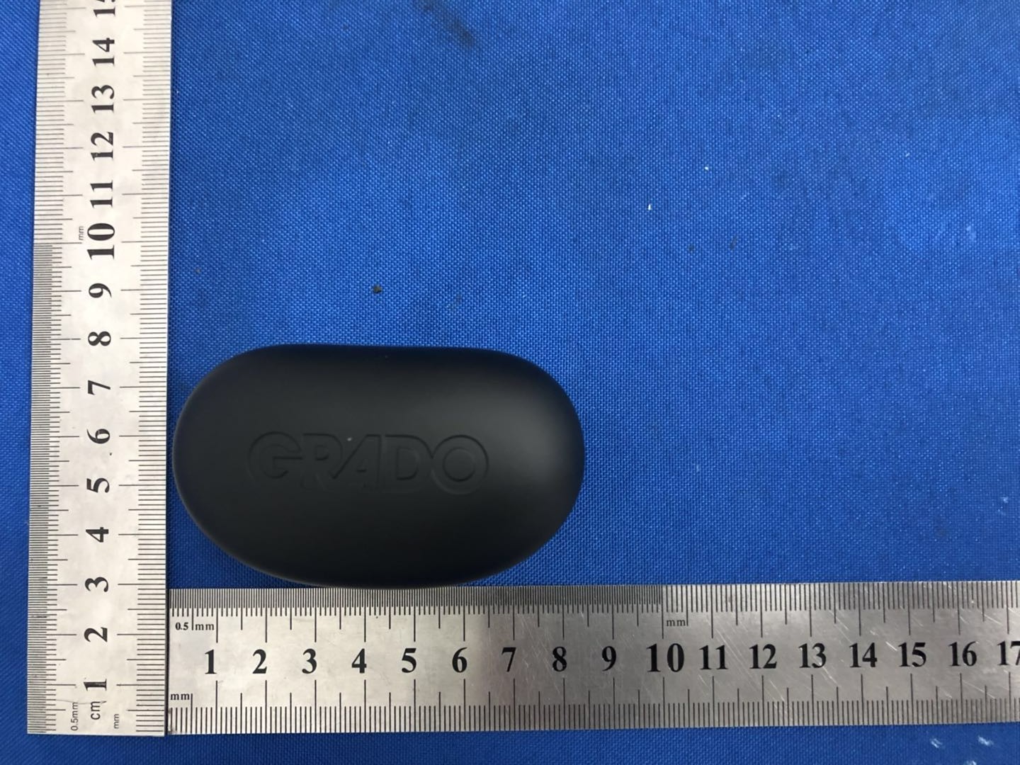
True Wireless Stereo headphone - FCC ID 2AQMIGT22020 - Grado Laboratories,inc
2AQMIGT22020

True Wireless Stereo headphone

Jun 17, 2020

Equipment Class

DSS - Part 15 Spread Spectrum Transmitter