2AQOP-IXSW112Switch Mini wireless Controller
SHENZHEN LIDACHENG TECHNOLOGY CO.,LTD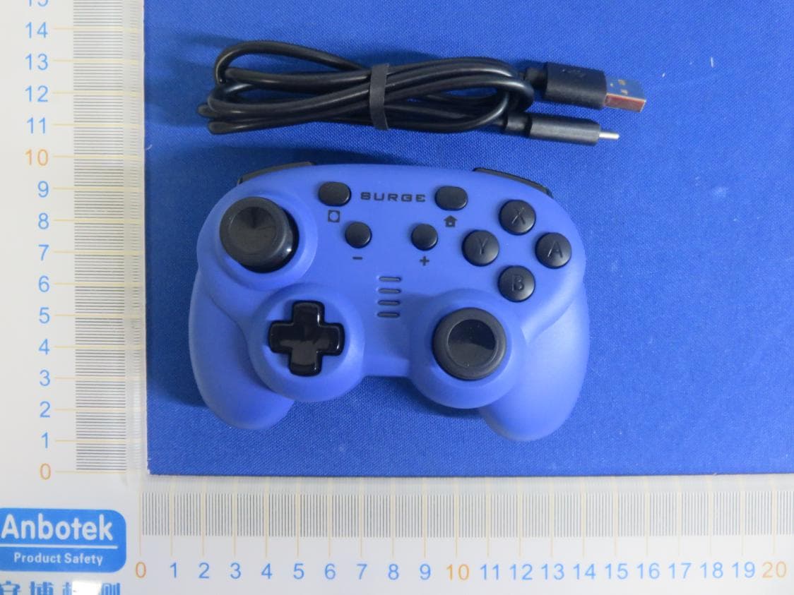
Click to zoom
Application Details
- Equipment Class
- DSS - Part 15 Spread Spectrum Transmitter
- Date of Grant
- Jun 08, 2020
- Application Purpose
- Original Equipment
- Date of Application
- Jun 07, 2020
- Equipment Note
- Switch Mini wireless Controller
- Frequency Range
- 2402.00000000 - 2480.00000000
- Country
- China
Documents & Files
Document Text
Text extracted from the exhibit documents filed with the FCC. Open a document above to read the original.
Users Manual
IX-SW112 Switch mini Wireless Controller Specifications File : Date : 2019/09/18 Version :A4 1 Model: IX-SW112 I . Controller schematic diagram Note : 3D Left Joystick can be L3 when vertical press; 3D Right Joystick can be R3 when vertical press, reset button is a little holeon back ofthe controller. IX-SW112 Switch mini Wireless Controller Specifications File : Date : 2019/09/18 Version :A4 2 II . Overview 1.Support Nintendo Switch Console above 3.0.0. 2.Wireless Controller Bluetooth transmission distance is 8-10M without barrier. 3.Wired mode supportSWITCH,PC XINPUT and PC D_INPUT. 4.Controller buttons: Up, Down, Left, Right, A, B, X, Y, L, R, ZL, ZR, L3, R3, +, -, HOME, Screen capture, reset. 5.Support two 3D analog joysticks. 6.Auto-sleep: will enter into auto-sleep mode ifno operations in 5 minutes or failed to connect with previous controller. 7.Controller support six axis. 8.Controller support updating program through USB cable(Controller should press reset button once to work properly after updating program). 9.Wireless controller reset button, press once can resume to default settings. 10.Controller working Voltage: DC 3.7V, working current: 30mA ± 5mA III. Operation Instruction Note: Set your controller before using for Wired Controller Step 1: Turn on Switch console, enter into console ’ s main interface; Step 2: Choose“System Settings”, select“Controllers and Sensors”; Step 3: Set “ Controller Vibration ” switch into “ ON ”; Step 4: Set “ Pro Controller Wired Communication ” switch into “ ON ”; 1. SWITCH console Bluetooth connection Step 1: Entering SWITCH console connecting mode, Step 2: Controller enter into pairing mode bypressing Y+HOME 3s. Four channel indicators will continuous light from top to bottom accordingly. In 2 minutes, controller has one or a few LED solid lights that shows connecting succeed (channel lights allocated by SWITCH console) Step 3: Press controller button A to confirm. And enter into Switch console settings or start game. 2. SWITCH wired connection (with OTG cable) Step 1: Connect OTG cable with console Step 2: Connect controller USB cable with OTG cables’USB port, and press button A to confirm. Connect succeed, blue channel lights is allocated bySwitch console and that shows player can start game. 3. SWITCH console wired connection through docking Step 1: Turn on Switch console, enter into main interface ; Step 2: Controller connect with TV through Dock and output video to TV ; Step 3: Connect controller USB with Dock USB port, press controller button A to confirm. Connect IX-SW112 Switch mini Wireless Controller Specifications File : Date : 2019/09/18 Version :A4 3 succeed, blue channel lights is allocated by Switch console and that shows player can start game. 4. PC wired connection (PC mode not support Bluetooth connection) Wired mode support X-INPUT & D-INPUT, shift by pressing HOME button 5s and support dynamic shift, no need to re-insert controller USB cable. Also it memories previous operate mode. LED 1 and LED2 will be solid light when under PC Xinput mode; LED 2 and LED3 will be solid light when under PC Dinput simulation mode; LED 1 and LED3 will be solid light when under PC Dinput digital mode; PC Dinput simulation mode and PC Dinput digital mode can be shift by short press HOME button. IV . Controller supported platforms Wired mode: supportSWITCH 、 PC DINPUT 、 PC XINPUTmode Wireless Bluetooth mode: SWITCH mode V.Different LED lights on different platforms PC XINPUT:■■□□ PC DINPUT(simulation mode):□■■□ PC DINPUT(digital mode):■□■□ Switch:Auto allocation VI . Controller Power on/off Status and Mode Instruction Controller power off : Long press HOME button 5s to power off Controller Code match status:Controller’s LED light will be solid one by one when after entering Code match mode, corresponding mode LED light is solid if Bluetooth connecting success. Controller will auto-sleep if code match not success in 2mins. Connecting previous console mode:Controller can be waked by pressing HOME button 3s, and will auto match previous console. Its corresponding mode LED flashes with 2Hz (lower flash). The corresponding mode LED light is solid when Bluetooth success connect. Controller will auto-sleep when failed connection after 20s. Low-voltage of battery : LED flashes(short flash) according to different mode. Battery specifications: IX-SW112 Switch mini Wireless Controller Specifications File : Date : 2019/09/18 Version :A4 4 Controller built in 3.7V/350mAH lithium battery which can repeat charge. The charging time is about 2 hours and the usage time can up to 8 hours after full-charged. Remarks: The above charging time and usage time data are for reference only. VII .Device name on different modes PC DINPUT: Device name shows CYBER GRYO CONTROLLERMINIfor SWITCH PC XINPUT: Device name shows Xbox 360 Controller for Windows NO.ItemStandard Parameter 1Rated Voltage 3.7V 2Rated Capability350mAh 3 Internal Impedance ≤ 120m Ω 4Charge Limit Voltage 4.20 ± 0.05V 5Discharge Limit Voltage 2.8 ± 0.05V 6Overcharge Detection Voltage 4.275 ± 0.025V 7Overcharge Release Voltage4.175-0.025V 8Discharge Limit voltage 2.8 ± 0.05V 9Over-discharge Detection Voltage 2.75 ± 0.08V 10Over-discharge Release Voltage 2.85±0.05V 11Over-current Detection value 2.2±0.05A 12Battery size6.0*17*35MM Cable Length 35MM IX-SW112 Switch mini Wireless Controller Specifications File : Date : 2019/09/18 Version :A4 5 FCC STATEMENT : This device complies with Part 15 of the FCC Rules. Operation is subject to the following two conditions: This device may not cause harmful interference, and This device must accept any interference received, including interference that may cause undesired operation. Warning: Changes or modifications not expressly approved by the party responsible for compliance could void the user's authority to operate the equipment. NOTE: This equipment has been tested and found to comply with the limits for a Class B digital device, pursuant to Part 15 of the FCC Rule…
Text truncated - open the document above for the full version.
External Photos
FCC ID: 2AQOP-IXSW112
ID Label/Location Info
Label Location On EUT Label Product Name: Switch Mini wireless Controller Model No.: IX-SW112 FCC ID: 2AQOP-IXSW112 This device complies with Part 15 of the FCC Rules. Operation is subject to the following two conditions: (1) This device may not cause harmful interference, and (2)This device must accept any interference received, including interference that may cause undesired operation.
Operational Description
version01 SHENZHEN LIDACHENG TECHNOLOGY CO.,LTD Declaration concerning Antenna Specification It is hereby declared that the product Model No.: IX-SW112, SG60063 FCCID:2AQOP-IXSW112 fulfills the requirement in FCC test relating to the antenna type. The device specified above confirms to the FCC recommendations for internal antenna type(s) described below: Model No. of antenna: N/A Type of antenna: PCB Antenna Gain of the antenna: -0.424 dBi Frequency range: 2402-2480MHz The mounting of the antenna is fixed to the radio module and no other antenna should be used. Company name: SHENZHEN LIDACHENG TECHNOLOGY CO.,LTD Address: 2/F, Building 16, 3rd Industrial Zone, Fenghuang Xingwei, Fuyong Street, Baoan District, Shenzhen, China City: Shenzhen ZIP / Postal code: N/A Country:China Place:ShenzhenDate: 2020-06-04 Signature:
RF Exposure Info
RF EXPOSURE EVALUATION FCC ID: 2AQOP-IXSW112 According to FCC 1.1310: The criteria listed in the following table shall be used to evaluate the environment impact of human exposure to radio frequency(RF) Radiation as specified in §1.1307(b): Routine SAR evaluation refers to that specifically required by §2.1093, using measurements or computer simulation. When routine SAR evaluation is not required, portable transmitters withoutput power greater than the applicable low threshold require SAR evaluation to qualify for TCB approval. Channel (MHz) Maximum output power (dBm) Tune up tolerance (dBm) Max Tune Up Power (dBm) Distance (mm) Calculation results Limit Operating Mode 2402-2.177 -2.177±1 -1.17750.2363 BDR+EDR 2441-0.467 -0.467±10.53350.3533 24800.834 0.834±1 1.83450.4803 2402-2.767 -2.767±1 -1.76750.2063 2441-1.226 -1.226±1-0.22650.2973 2480-0.051 -0.051±1 0.94950.3923 Test Results:PASS.
Test Report
Report No.: 18220WC00056001FCC ID: 2AQOP-IXSW112Page 1 of 63 Code:AB-RF-05-a FCC TEST REPORT Client Name: SHENZHEN LIDACHENG TECHNOLOGY CO.,LTD Address: 2/F, Building 16, 3rd Industrial Zone, Fenghuang Xingwei, Fuyong Street, Baoan District, Shenzhen, China Product Name: Switch Mini wireless Controller Date: Jun. 04, 2020 Shenzhen Anbotek Compliance Laboratory Limited Report No.: 18220WC00056001FCC ID: 2AQOP-IXSW112Page 2 of 63 Code:AB-RF-05-a Contents 1. General Information ............................................................................................................................................... 5 1.1. Client Information ....................................................................................................................................... 5 1.2. Description of Device (EUT) ..................................................................................................................... 5 1.3. Auxiliary Equipment Used During Test ................................................................................................... 6 1.4. Description of Test Modes ........................................................................................................................ 6 1.5. List of channels ........................................................................................................................................... 7 1.6. Description Of Test Setup ......................................................................................................................... 8 1.7. Test Equipment List .................................................................................................................................... 9 1.8. Measurement Uncertainty ....................................................................................................................... 10 1.9. Description of Test Facility ...................................................................................................................... 10 2. Summary of Test Results ................................................................................................................................... 11 3. Conducted Emission Test ................................................................................................................................... 12 3.1. Test Standard and Limit .......................................................................................................................... 12 3.2. Test Setup .................................................................................................................................................. 12 3.3. Test Procedure .......................................................................................................................................... 12 3.4. Test Data .................................................................................................................................................... 12 4. Radiation Spurious Emission and Band Edge ................................................................................................ 17 4.1. Test Standard and Limit .......................................................................................................................... 17 4.2. Test Setup .................................................................................................................................................. 17 4.3. Test Procedure .......................................................................................................................................... 18 4.4. Test Data .................................................................................................................................................... 19 5. Maximum Peak Output Power Test .................................................................................................................. 27 5.1. Test Standard and Limit .......................................................................................................................... 27 5.2. Test Setup .................................................................................................................................................. 27 5.3. Test Procedure .......................................................................................................................................... 27 5.4. Test Data .................................................................................................................................................... 27 6. 20DB Occupy Bandwidth Test ........................................................................................................................... 31 6.1. Test Standard ............................................................................................................................................ 31 6.2. Test Setup .................................................................................................................................................. 31 6.3. Test Procedure .......................................................................................................................................... 31 6.4. Test Data .................................................................................................................................................... 31 7. Carrier Frequency Separation Test ................................................................................................................... 35 7.1. Test Standard and Limit .......................................................................................................................... 35 7.2. Test Setup .................................................................................................................................................. 35 7.3. Test Procedure ...........................................................................................…
Text truncated - open the document above for the full version.
Test Setup Photos
FCC ID: 2AQOP-IXSW112 Photo of Conducted Emission Measurement Photo of Radiation Emission Test
Contact Information
Applicant
Ben zhang(Manager)
Test Firm
Shenzhen Anbotek Compliance Laboratory LimitedJeff Zhu
Technical Specifications
| # | Rule Parts | Frequency Range | Power Output |
|---|---|---|---|
| 1 | 15C | 2.40 GHz - 2.48 GHz | 1.22 mW |
Other Applications from SHENZHEN LIDACHENG TECHNOLOGY CO.,LTD
2AQOP-IX-SW227
Aug 05, 2023NSA WIRELESS PRO CONTROLLER
Equipment Class
DSS - Part 15 Spread Spectrum Transmitter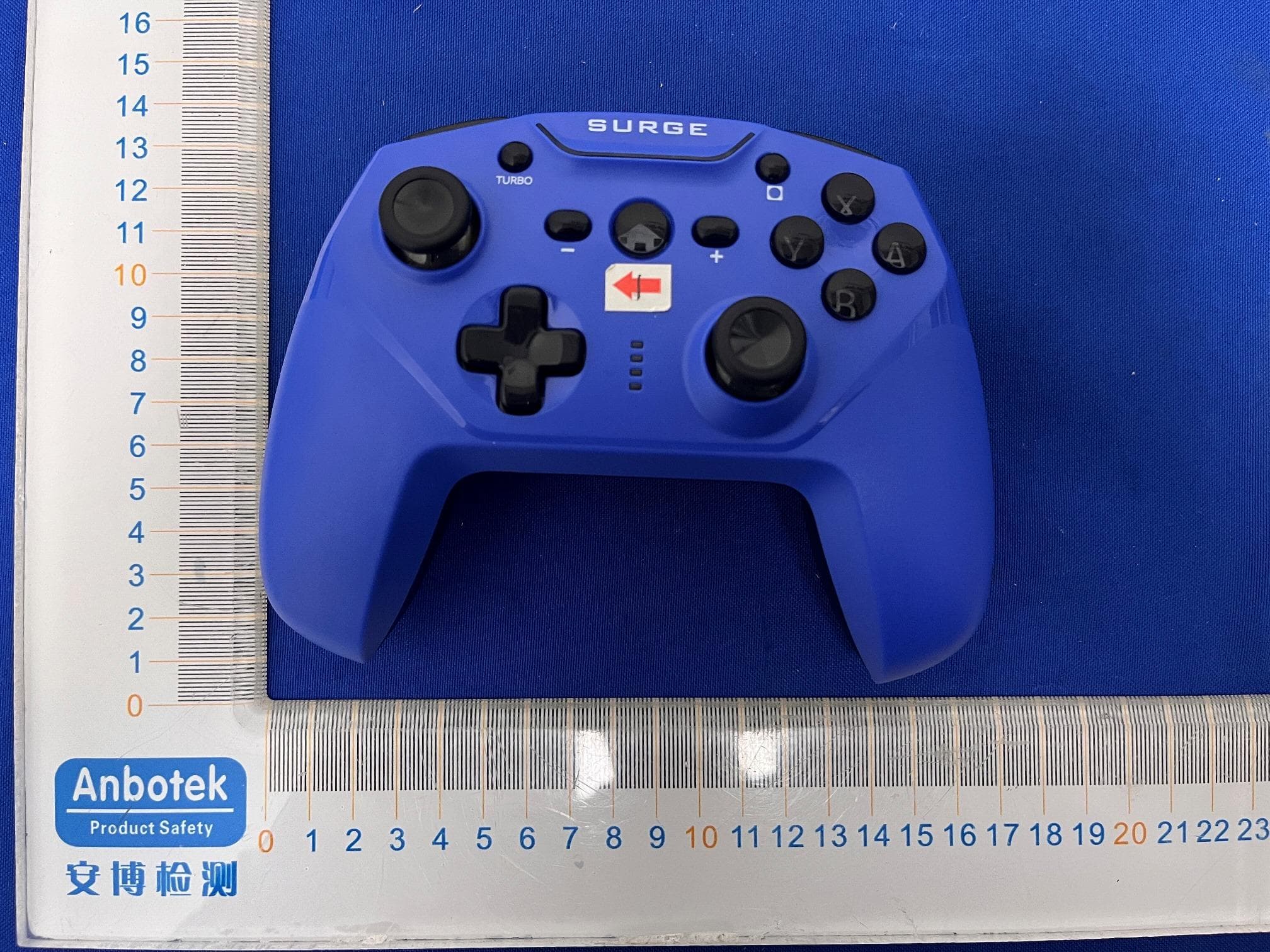
2AQOP-IX-SW055
Feb 19, 2023SURGE NSA WIRELESS PRO CONTROLLER
Equipment Class
DSS - Part 15 Spread Spectrum Transmitter