2AQU7-REAL02HMD for REAL Immersive System
Penumbra Inc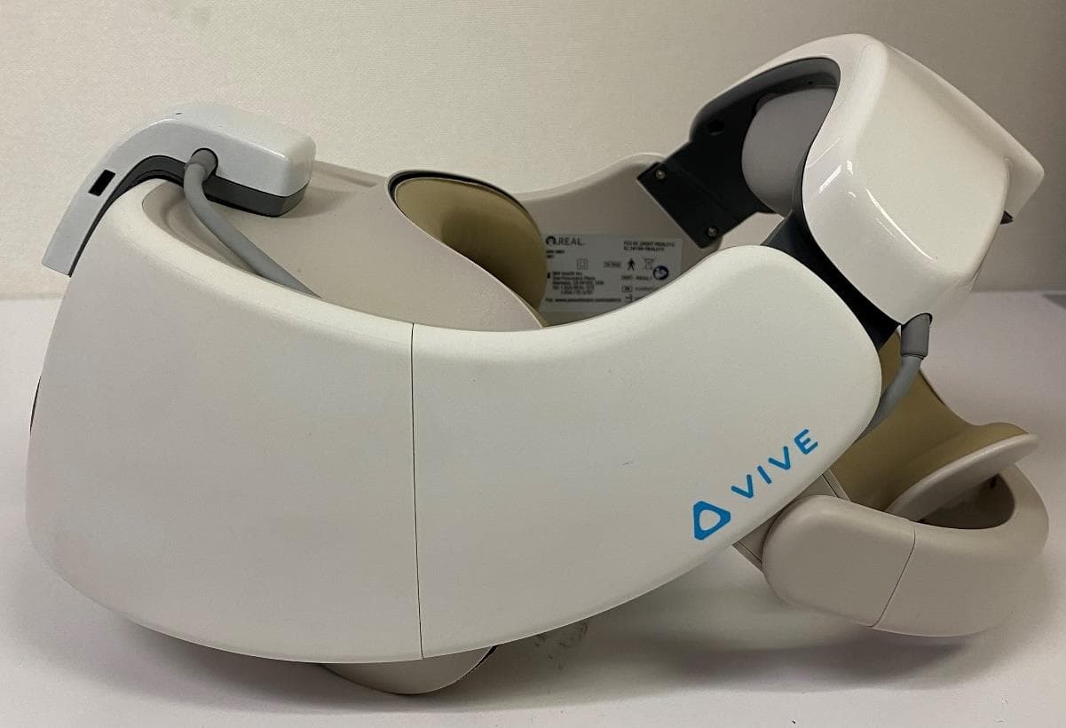
Click to zoom
Application Details
- Equipment Class
- DTS - Digital Transmission System
- Date of Grant
- Apr 20, 2021
- Application Purpose
- Original Equipment
- Date of Application
- Apr 20, 2021
- Equipment Note
- HMD for REAL Immersive System
- Frequency Range
- 2402.00000000 - 2479.00000000
- Company
- Penumbra Inc
- Country
- United States
Documents & Files
Document Text
Text extracted from the exhibit documents filed with the FCC. Open a document above to read the original.
Users Manual
1 (15) REAL ™ IMMERSIVE SYSTEM USER MANUAL Table of Contents Warning 3 Device Description 3 Indication for Use 4 Contraindications 4 Warnings 4 Precautions 4 Potential Adverse Effects/Events 4 Operating Profile 5 Operating Procedure 5 • Getting Started & Charging Components 5 • Internet Connectivity 6 • Start-Up System for Patient Use 6 • Therapy Activities 8 • System Removal 9 • Software Description 10 Technical Specifications 13 Symbol Glossary 13 Technical Information 13 WARNING! CAREFULLY READ ALL INSTRUCTIONS PRIOR TO USE. OBSERVE ALL WARNINGS AND PRECAUTIONS NOTED THROUGHOUT THESE INSTRUCTIONS. FAILURE TO DO SO MAY RESULT IN COMPLICATIONS. 2 (15) DEVICE DESCRIPTON The REAL ® Immersive System is a digital hardware and software medical device platform utilizing virtual reality technology designed for use in a clinical environment, or any other facility that may facilitate rehabilitation, setting that focuses on physical, neurorehabilitation and/or wellness needs. REAL Immersive System consists of following components: • All-In-One Headset with Software Application • Headset Controller • Large Sensor • Small Sensors • Tablet • Sensor Charger (charging station) • REAL Sensor Bands Tablet is fitted with a touch screen, a power/lock key that turns the component on or off, and a charger/accessory port. The headset contains a power button that turns the component on or off and a charger/ accessory port. The headset also provides visual feedback of virtual reality applications in concert with the REAL Immersive System tablet and small and large sensors. Large and small sensors (WTM and WSMs) are equipped with mechanical and electrical components that measure motion and direction in physical space and then translate that information into a virtual environment. The sensor charger powers the sensors. Headset controller (Only to be used in certain troubleshooting and administrative tasks. Not used during patient therapy.) At full charge, the entire system can last at a minimum of 60 minutes and it is recommended that a therapy session does not exceed 60 minutes. Please sufficiently charge all components between use for a minimum of 60 minutes. In the event of electromagnetic disturbances, the performance of the REAL Immersive System may be affected. The REAL Immersive System is a Type BF Applied Part. Frequently used features and functions: Headset • Plug headset power cord into wall outlet and headset to charge device. • Press power button to power on headset or restart headset. The power button is on top of the headset. Headset Controller • Buttons on the controller are used to control power, connect to headset, access settings, or control volume. Large Sensor and Small Sensors • Components are removed or placed back into the sensor charger (charging station) to activate or charge device. • Components are placed into the sensor bands. Tablet • Plug tablet power cord into wall outlet and tablet to charge device. • Press power button to power on tablet or restart tablet. The power button is on the edge of the device. • User Interface: - Selecting the application - Logging in - Adding or selecting patient - Initializing and syncing to sensors - Selecting, starting, modifying, or ending therapy session - Viewing data - Logging out Sensor Charger • Plug sensor charger power cord into wall outlet and sensor charger to power on device to charge sensors. Sensor Bands • Place or remove sensor bands on or from patient. There is no preventive inspection, calibration, and maintenance necessary for the REAL Immersive System besides the initial set up procedure. During the three-year product lifespan of the REAL Immersive System, the device will continue to perform safely without any routine maintenance. No parts within the REAL Immersive System will require inspection nor maintenance by a service personnel to ensure basic safety during the three-year product lifespan. Circuit diagrams and calibration instructions are not provided because service or parts repair is not necessary. At the end of the three-year product lifespan, the user should dispose of the device through an environmentally safe electronic waste recycle system. Contact the local REAL representative if the following event occurs: • The system no longer stays powered on and connected through the entire recommended duration of a therapy session. Supply mains are electrically isolated in medical equipment to maintain basic safety. 3 (15) The full expected latency of the device, including movement detection, processing, and visual representation is 35 milliseconds or less. This value is considered minimal and sufficiently low enough so that movement can be quickly detected. INDICATION FOR USE The REAL ™ Immersive System is an immersive virtual reality and display system that interactively displays and tracks upper-extremity rehabilitation exercises for adult pa- tients using a combination of virtual environments and full presence tracked avatars for visual feedback. These rehabilitation exercises are intended to be conducted in a seated position in a clinical environment or any other facility that may facilitate rehabilitation and prescribed and supervised by a medical professional trained in rehabilitation therapy. CONTRAINDICATIONS There are no known contraindications. WARNINGS If a patient complains of motion sickness, dizziness, headache, eye strain, or fatigue when using the device, stop use of device immediately. Use caution when using this device if a patient has a history of vestibular issues or motion sickness. PRECAUTIONS Ensure a safe environment for the patient while performing activities with the device (e.g. remove any surrounding obstacles and ensure that the patient is unlikely to trip or fall). As this device is to be used for upper body rehabilitation, we recommend that the patient remain seated to avoid a fall. Be aware of the patient’s limitations in range of motion and avoid device or program use that could lead to excessive…
Text truncated - open the document above for the full version.
Users Manual
Page 1 of 29 REAL® SYSTEM 2 User Manual Table of Contents Abbreviations?? Warning 3 Device Description 3 Indication for use 4 Contraindications 4 Warnings 4 Precautions 4 Potential Adverse Effects/Events 4 Operating Profile 5 Operating Procedure 5 • Getting Started & Charging Components 5 • Internet Connectivity 6 • Start-Up System for Patient Use 6 • Therapy Activities 8 • System Removal 9 • Software Description 10 Technical Specifications 13 Symbol Glossary 13 Technical Information 13 Troubleshooting Guide WARNING! CAREFULLY READ ALL INSTRUCTIONS PRIOR TO USE. OBSERVE ALL WARNINGS AND PRECAUTIONS NOTED THROUGHOUT THESE INSTRUCTIONS. FAILURE TO DO SO MAY RESULT IN COMPLICATIONS. DEVICE DESCRIPTON The REAL® System 2 is a digital hardware and software medical device platform utilizing virtual reality technology designed for use in residential or rehabilitation setting that focuses on physical, neurorehabilitation and/or wellness needs. REAL System 2 consists of following components: Page 2 of 29 • All-In-One Headset with Software Application • Headset Controller • Large Sensor • Small Sensors • Sensor Charger (charging station) • REAL Sensor Bands The headset contains a power button that turns the component on or off and a charger/accessory port. The headset also provides visual feedback of virtual reality applications in concert with the REAL System 2 small and large sensors. Large and small sensors are equipped with mechanical and electrical components that measure motion and direction in physical space and then translate that information into a virtual environment. The sensor charger powers the sensors. Headset controller can be used to perform administrative tasks such as connect to network, select therapy activity, access settings, etc. At full charge, the entire system can last at a minimum of 60 minutes and it is recommended that a therapy session does not exceed 60 minutes. The expected amount of time to charge the system to last the recommended therapy session time is 60 minutes. In the event of Electromagnetic disturbances, the performance of the REAL System 2 may be affected. The REAL System 2 is a Type BF Applied Part. Frequently used features and functions: Headset • Plug the headset power cord into wall outlet and the headset to charge device. • Press power button to power on or off headset. The power button is on top of the headset. Headset Controller • Buttons on the controller are used to access settings. Sensor Charger • Plug sensor charger power cord into wall outlet and sensor charger to power on device to charge sensors. Page 3 of 29 Large Sensor and Small Sensors • Activate or charge sensor devices by removing or placing back into the sensor charging station. • Place sensor devices into the sensor bands. Sensor Bands • See Section 3 in Operating Procedures on instructions to put on sensor bands. User Portals • Access the User Portal through the Headset to perform the following: o Logging in o Selecting the activity o Initializing and syncing to sensors o Starting, modifying, or ending therapy session o Viewing data o Logging out • HCP Portal o Selecting the application o Logging in o Adding or selecting patient o Initializing and syncing to sensors o Selecting, starting, modifying, or ending therapy session o Viewing data o Logging out There is no preventive inspection, calibration, and maintenance necessary for the REAL System 2 besides the initial set up procedure. During the three-year product lifespan of the REAL System 2, the device will continue to perform safely without any routine maintenance. No parts within the REAL System 2 will require inspection nor maintenance by a service personnel to ensure basic safety during the three-year product lifespan. Circuit diagrams and calibration instructions are not provided because service in parts repair is not necessary. If the system no longer stays powered on and connected through the entire recommended duration of a therapy session, dispose of the device through an environmentally safe electronic waste recycle system. If the sensor bands no longer adequately hold the sensors nor stay strapped to your body, dispose of the sensor bands and reorder through the REAL website. Supply mains are electrically isolated in medical equipment to maintain basic safety. Page 4 of 29 The full expected latency of the device, including movement detection, processing, and visual representation is 35 milliseconds or less. This value is considered minimal and sufficiently low enough so that movement can be quickly detected. INDICATION FOR USE The REAL System 2 is an immersive virtual reality and display system that interactively displays and tracks rehabilitation exercises using a combination of virtual environments and full presence tracked avatars for visual feedback. These rehabilitation exercises are intended to be conducted in a seated position in a residential environment, or any other facility that may facilitate rehabilitation. CONTRAINDICATIONS There are no known contraindications. WARNINGS If motion sickness, dizziness, headache, eye strain, or fatigue is experienced when using the device, stop use of device immediately. Use caution when using this device if you have a history of vestibular issues or motion sickness. Precautions Ensure a safe environment while performing activities with the device (e.g. remove any surrounding obstacles that may lead to injuries caused by trips and falls). As this device is to be used for upper body rehabilitation, it is required to remain seated to avoid a fall. Be aware of the limitations in range of motion and avoid device or program use that could lead to excessive gestures that could result in injuries. Extended use of the headset can cause discomfort or eye strain. Incorrect placement of the sensors may result in the avatar appearing incorrectly or distorted on the headset. Damage (mechanical and electrical) may result if the headset, sensors, and/or sensor charger are dropped or struck a…
Text truncated - open the document above for the full version.
Cover Letter(s)
4/ 20/2021 Attention: Application Examiner RE: Family Certification Information Applicant: Penumbra Inc. FCC: 2AQU7-REAL02 To Whom It May Concern: REAL is a digital hardware and software medical device platform utilizing virtual reality technology designed for use in healthcare and focusing on physical, neurorehabilitation and/or wellness needs. REAL is offered in two configurations: REAL System and REAL System 2. REAL System is intended to be used in a clinical environment, or any other facility that may facilitate rehabilitation by healthcare providers who have received appropriate training in rehabilitation therapy. REAL System 2 is intended to be used in a residential environment, or any other facility that may facilitate rehabilitation individuals with physical, neurorehabilitation and/or wellness needs. A caregiver may be optionally present to help the user operate the system. Both configurations use the same sensor modules listed under FCC: 2AQU7-REAL02 (HVIN: HMD2). Headset plastic, Sensor Charger, User Manual, and Label content differences between the two configurations is for home healthcare compliance purposes and does not alter the functionality between REAL System and REAL System 2. Sincerely, Puneet Goyal R&D Engineer III Penumbra Inc.
External Photos
HMD External Photos View Photo HTC VIVE Front HTC VIVE Back HTC VIVE Left HTC VIVE Right HTC VIVE Top HTC VIVE Bottom Accessory and Interface HTC VIVE + Accessory and Interface Front HTC VIVE + Accessory and Interface Back HTC VIVE + Accessory and Interface Left HTC VIVE + Accessory and Interface Right HTC VIVE + Accessory and Interface Top HTC VIVE + Accessory and Interface Bottom
ID Label/Location Info
Label Location
ID Label/Location Info
Label Location
Internal Photos
HMD Internal Photos View Photo With Accessory Top Housing Off With Interface Housing Off In- Housing Front Accessory PCBA Top Accessory PCBA Bottom Interface PCBA Top Interface PCBA Bottom
Internal Photos
HMD Internal Photos View Photo With Accessory Top Housing Off With Interface Housing Off In- Housing Front Accessory PCBA Top Accessory PCBA Bottom Interface PCBA Top Interface PCBA Bottom
RF Exposure Info
© 2020 RF Exposure Lab, LLC This report shall not be reproduced except in full without the written approval of RF Exposure Lab, LLC. 802 N. Twin Oaks Valley Road, Suite 105 • San Marcos, CA 92069 • U.S.A. TEL (760) 471-2100 • FAX (760) 471-2121 http://www.rfexposurelab.com CERTIFICATE OF COMPLIANCE SAR EVALUATION Penumbra, Inc. Dates of Test: December 29, 2020 One Penumbra Place Test Report Number: R&D.20201203 Alameda, CA 94502 Revision A This wireless mobile and/or portable device has been shown to be compliant for localized specific absorption rate (SAR) for uncontrolled environment/general exposure limits specified in ANSI/IEEE Std. C95.1-1992 and had been tested in accordance with the measurement procedures specified in IEEE 1528-2013 and IEC 62209-2:2010 (See test report). I attest to the accuracy of the data. All measurements were performed by myself or were made under my supervision and are correct to the best of my knowledge and belief. I assume full responsibility for the completeness of these measurements and vouch for the qualifications of all persons taking them. RF Exposure Lab, LLC certifies that no party to this application is subject to a denial of Federal benefits that includes FCC benefits pursuant to Section 5301 of the Anti-Drug Abuse Act of 1988, 21 U.S.C. 853(a). Jay M. Moulton Vice President Testing Cert. # 2387.01 FCC ID: 2AQU7-REAL02 IC Certificate: 24199-REAL02 Model(s) Number: Xavier1 & Xavier2 Model(s) Name: HMD, All-In-One Head Mounted Display Test Sample: Engineering Unit Same as Production Serial No.: N/A Equipment Type: Wireless VR Headset Classification: Portable Transmitter TX Frequency Range: 2412 – 2462 MHz; 2402 – 2480 MHz; 5180 – 5320 MHz; 5500 – 5700 MHz; 5745 – 5825 MHz Frequency Tolerance: ± 2.5 ppm Maximum RF Output: 2450 MHz (b) – 19.0 dBm, 2450 MHz (g) – 19.0 dBm, 2450 MHz (n20) – 17.5 dBm, 2450 MHz (n40) – 12.5 dBm, 2450 MHz (ac/ax) – 17.5 dBm, 5250 MHz (a) – 18.5 dBm, 5250 MHz (n20) – 18.5 dBm, 5250 MHz (n40) – 18.5 dBm, 5250 MHz (ac/ax) – 18.5 dBm, 5600 MHz (a) – 18.5 dBm, 5600 MHz (n20) – 18.5 dBm, 5600 MHz (n40) – 18.5 dBm, 5600 MHz (ac/ax) – 18.5 dBm, 5800 MHz (a) – 18.5 dBm, 5800 MHz (n20) – 18.5 dBm, 5800 MHz (n40) – 18.5 dBm, 5800 MHz (ac/ax) – 18.5 dBm, Bluetooth (Internal to VR Headset) – 7.5 dBm, Proprietary Transmitter (Added to VR Headset) – 10.0 dBm Conducted Signal Modulation: DSSS, OFDM, GFSK, 8DPSK, π/4 DPSK Antenna Type: Internal Application Type: Certification FCC Rule Parts: Part 2, 15C, 15E KDB Methodology: KDB 447498 D01 v06 Industry Canada: RSS-102 Issue 5, Safety Code 6 Maximum SAR Value: 0.42 W/kg (From VR Original Report) 1 gram Average Maximum SAR Value: 0.51 W/kg (From VR Original Report) 10 gram Average Maximum Simultaneous SAR: 1.02 W/kg 1 gram Average (Head) Maximum Simultaneous SAR: 0.75 W/kg 10 gram Average (Extremity) Separation Distance: 0 mm Report No.: R&D.20201203 © 2020 RF Exposure Lab, LLC Page 2 of 13 This report shall not be reproduced except in full without the written approval of RF Exposure Lab, LLC. Table of Contents 1. Introduction ........................................................................................................................ 4 2. Evaluation of Additional Bluetooth Transmitters ................................................................. 4 2.1 Specifications of Additional Bluetooth Transmitters .................................................... 4 2.2 SAR Values Extracted from Original SAR Report for VR Headset .............................. 5 2.3 SAR Test Exclusion Evaluation for Additional Bluetooth Transmitters ........................ 5 2.4 Estimated SAR Value for Additional Bluetooth Transmitters ....................................... 6 2.5 Simultaneous Evaluation with Additional Bluetooth Transmitters ................................ 7 3. Photos of Device ................................................................................................................ 8 Report No.: R&D.20201203 © 2020 RF Exposure Lab, LLC Page 3 of 13 This report shall not be reproduced except in full without the written approval of RF Exposure Lab, LLC. Comment/Revision Date Original Release December 29, 2020 Revision A – Correct transmitter name to proprietary, headset on page 1 and frequency of proprietary transmitter to 2479 MHz. December 30, 2020 Report No.: R&D.20201203 © 2020 RF Exposure Lab, LLC Page 4 of 13 This report shall not be reproduced except in full without the written approval of RF Exposure Lab, LLC. 1. Introduction This measurement report shows compliance of the Penumbra, Inc. Model Number Xavier 1 & Xavier 2 Model Name HMD, All-In-One Head Mounted Display FCC ID: 2AQU7-REAL02 with FCC Part 2.1093, ET Docket 93-62 Rules for mobile and portable devices and IC Certificate: 24199-REAL02 with RSS-102 Issue 5 & Safety Code 6. The FCC has adopted the guidelines for evaluating the environmental effects of radio frequency radiation in ET Docket 93-62 on August 6, 1996 to protect the public and workers from the potential hazards of RF emissions due to FCC regulated portable devices. The device is a wireless virtual reality headset with the addition of two(2) Proprietary transmitters. The headset by itself is a pre-approved device manufactured by HTC Corporation model number 2Q9R100. The FCC ID for the headset is NM82Q9R100 and the ISED certificate number is 4115A-2Q9R100. The data was extracted from the report dated September 10, 2020 report number FA073116-02. This analysis report takes the original SAR data from the FCC filing under FCC ID NM82Q9R100 and ISED certificate number 4115A-2Q9R100. Using this data, this report shows the compliance of adding the two(2) proprietary transmitters to the headset. The simultaneous evaluation is calculated and shown to comply within this report. The two models are identical electrically. The only difference is the Xavier 2 has an extended piece of plastic in the front of the device as shown in the photos in section 3 of this re…
Text truncated - open the document above for the full version.
Test Report
EMC Report for Penumbra, Inc. on the All-In-One Head Mounted Display (Part Number: 19135) File: 104407842MPK-014 Page 1 of 98 TEST REPORT Report Number: 104407842MPK-014 Project Number: G104407842 December 28, 2020 Testing performed on Real Immersive System Model: Xavier 1/Xavier 2 Part Number: 19135 ( HMD, All-In-One Head Mounted Display) FCC ID: 2AQU7-REAL02 IC: 24199-REAL02 to FCC Part 15 Subpart C (15.247) Industry Canada RSS-247 Issue 2 For Penumbra Inc. Test Performed by: Test Authorized by: Intertek 1365 Adams Court Menlo Park, CA 94025 USA Penumbra Inc. One Penumbra Place Alameda, CA 94502 USA Prepared by: Date: December 28, 2020 Aaron Chang Reviewed by: Date: December 28, 2020 Krishna K Vemuri This report is for the exclusive use of Intertek's Client and is provided pursuant to the agreement between Intertek and its Client. Intertek's responsibility and liability are limited to the te rms and conditions of the agreement. Intertek assumes no liability to any party, other than to the Client in accordance with the agreement, for any loss, expense or damage occasioned by the use of this report. Only the Client is authorized to copy or distr ibute this report and then only in its entirety. Any use of the Intertek name or one of its marks for the sale or advertisement of the tested material, product or service must first be approved in writing by Intertek. The observations and test results in this report are relevant only to the sample tested. This report by itself does not imply that the material, product, or service is or has ever been under an Intertek certification program. This report must not be used to claim product endorsement by A2LA, NIST nor any other agency of the U.S. Government. EMC Report for Penumbra, Inc. on the All-In-One Head Mounted Display (Part Number: 19135) File: 104407842MPK-014 Page 2 of 98 Report No. 104407842MPK-014 Equipment Under Test: Real Immersive System - All-In-One Head Mounted Display Trade Name: Penumbra Inc. Model Number: Xavier 1/Xavier 2 Part Number: 19135 Applicant: Penumbra Inc. Contact: Puneet Goyal Address: Penumbra Inc. One Penumbra Place Alameda, CA 94502 Country: USA Tel. Number: (510) 440-5598 Email: [email protected] Applicable Regulation: FCC Part 15 Subpart C (15.247) Industry Canada RSS-247 Issue 2 Date of Test: September 22- 30, 2020 & December 6-9, 2020 We attest to the accuracy of this report: Aaron Chang Project Engineer Krishna K Vemuri EMC Manager EMC Report for Penumbra, Inc. on the All-In-One Head Mounted Display (Part Number: 19135) File: 104407842MPK-014 Page 3 of 98 TABLE OF CONTENTS 1.0 Summary of Tests .......................................................................................................................... 4 2.0 General Information ...................................................................................................................... 5 2.1 Product Description ............................................................................................................ 5 2.2 Related Submittal(s) Grants ................................................................................................ 6 2.3 Test Facility ........................................................................................................................ 6 2.4 Test Methodology ............................................................................................................... 6 2.5 Measurement Uncertainty ................................................................................................... 6 3.0 System Test Configuration ............................................................................................................ 7 3.1 Support Equipment ............................................................................................................. 7 3.2 Block Diagram of Test Setup .............................................................................................. 7 3.3 Justification ......................................................................................................................... 8 3.4 Software Exercise Program................................................................................................. 8 3.5 Mode of Operation during Test........................................................................................... 8 3.6 Modifications Required for Compliance ............................................................................ 8 3.7 Additions, Deviations and Exclusions from Standards ....................................................... 8 4.0 Measurement Results..................................................................................................................... 9 4.1 6- dB Bandwidth and 99% Occupied Bandwidth ................................................................ 9 4.2 Maximum Peak Conducted Output Power at Antenna Terminals .................................... 22 4.3 Maximum Power Spectral Density ................................................................................... 29 4.4 Out of Band Antenna Conducted Emission ...................................................................... 36 4.5 Transmitter Radiated Emissions ....................................................................................... 47 5.0 List of Test Equipment ................................................................................................................ 97 6.0 Document History ........................................................................................................................ 98 EMC Report for Penumbra, Inc. on the All-In-One Head Mounted Display (Part Number: 19135) File: 104407842MPK-014 Page 4 of 98 1.0 Summary of Tests Test Reference FCC Reference Industry Canada Result RF Output Power 15.247(b)(3) RSS-247, 5.4.d) Complies 6 dB Bandwidth 15.247(a)(2) RSS-247, 5.2.a) Complies Power Density 15.247(e) RSS-247, 5.2.b) Complies Out of Band Antenna Conducted Emis…
Text truncated - open the document above for the full version.
Test Setup Photos
Part Number: 19135 ( HMD, All-In-One Head Mounted Display)
Contact Information
Applicant
Royal Wang(R&D Manager)
Technical Contact
Penumbra IncPuneet Goyal
[email protected]7072469726
1 Penumbra Place · Alameda, California · United States
Test Firm
IntertekTesting Services NA Inc.Charles Parker
Technical Specifications
| # | Rule Parts | Frequency Range | Power Output |
|---|---|---|---|
| 1 | 15C | 2.40 GHz - 2.48 GHz | 6.37 mW |
Other Applications from Penumbra Inc
2AQU7-REAL02S
Apr 20, 2021WSM for REAL Immersive System
Equipment Class
DTS - Digital Transmission System
2AQU7-REAL02T
Apr 20, 2021WTM for REAL Immersive System
Equipment Class
DTS - Digital Transmission System