2AQUZ-DR2500Workwell Face Recognition Cloud Tablet Time Clock
Workwell Technologies, Inc.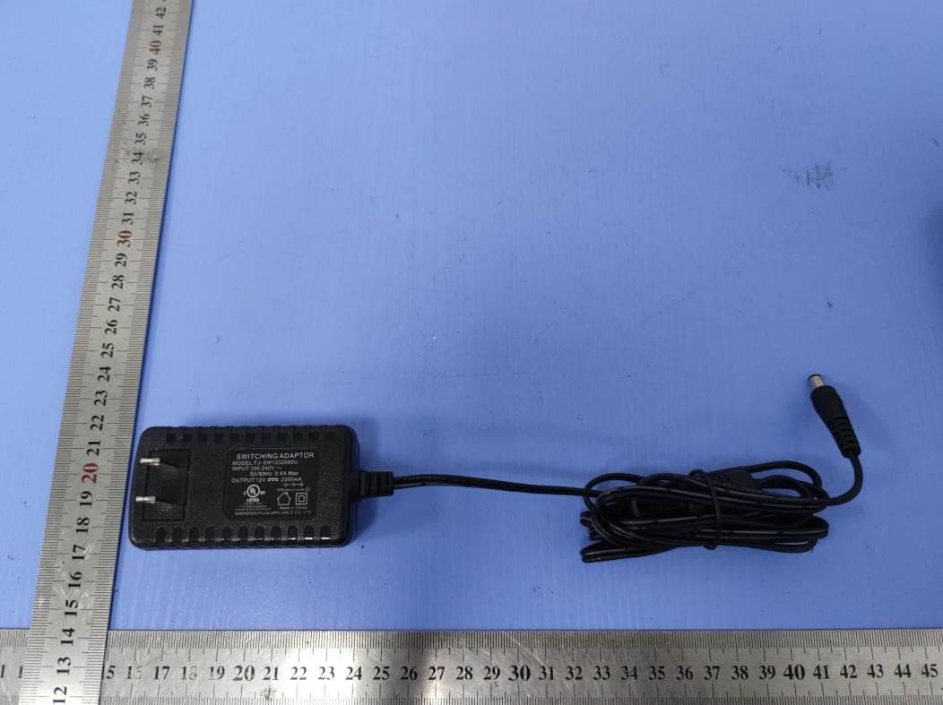
Click to zoom
Application Details
- Equipment Class
- DCD - Part 15 Low Power Transmitter Below 1705 kHz
- Date of Grant
- Nov 18, 2020
- Application Purpose
- Original Equipment
- Date of Application
- Nov 18, 2020
- Equipment Note
- Workwell Face Recognition Cloud Tablet Time Clock
- Frequency Range
- 0.12500000 - 0.12500000
- Company
- Workwell Technologies, Inc.
- Country
- United States
Documents & Files
Document Text
Text extracted from the exhibit documents filed with the FCC. Open a document above to read the original.
Users Manual
All information provided to David-Link in this document is the property of Workwell Technologies, Inc. and is condential and intended only for the direct recipients or those within the organization(s) working to develop products for Workwell Technologies, Inc. No part of this document may be disclosed in any manner to a third party without the prior written consent of Workwell Technologies, Inc. All information provided to David-Link in this document is the property of Workwell Technologies, Inc. and is condential and intended only for the direct recipients or those within the organization(s) working to develop products for Workwell Technologies, Inc. No part of this document may be disclosed in any manner to a third party without the prior written consent of Workwell Technologies, Inc. C O N F I D E N T I A L FCC Statement This device complies with part 15 of the FCC rules. Operation is subject to the following two conditions: (1) this device may not cause harmful interference, and (2) this device must accept any interference received, including interference that may cause undesired operation. Changes or modifications not expressly approved by the party responsible for compliance could void the user's authority to operate the equipment. NOTE: This equipment has been tested and found to comply with the limits for a Class B digital device, pursuant to part 15 of the FCC Rules. These limits are designed to provide reasonable protection against harmful interference in a residential installation. This equipment generates uses and can radiate radio frequency energy and, if not installed and used in accordance with the instructions, may cause harmful interference to radio communications. However, there is no guarantee that interference will not occur in a particular installation. If this equipment does cause harmful interference to radio or television reception, which can be determined by turning the equipment off and on, the user is encouraged to try to correct the interference by one or more of the following measures: ÿ Reorient or relocate the receiving antenna. ÿ Reorient or relocate the receiving antenna. ÿ Reorient or relocate the receiving antenna. ÿConsult the dealer or an experienced radio/TV technician for help important announcement Important Note: Radiation Exposure Statement This equipment complies with FCC radiation exposure limits set forth for an uncontrolled environment. This equipment should be installed and operated with minimum distance 20cm between the radiator and your body. This transmitter must not be co-located or operating in conjunction with any other antenna or transmitter. All informaon provided to David-Link in this document is the property of Workwell Technologies, Inc. and is confidenal and intended only for the direct recipients or those within the organizaon(s) working to develop products for Workwell Technologies, Inc. No part of this document may be disclosed in any manner to a third party without the prior wrien consent of Workwell Technologies, Inc. uAend Cloud Time Clock Descripon: uAend me clocks work in conjuncon with the online cloud account and allows customers to automate their me and aendance management. Employees use the me clocks to record their punch mes which are then sent to the online account, while the uAend online account gives customers the ability to streamline their processes using the system’s automated me card calculaon engine. Time Clock Features: Allows employees to authencate for me and aendance punching by scanning a fingerprint, RFID or entering a unique personal idenficaon number (PIN). Allows employees to perform In/Out, Break/Lunch, Department transfer and Job punches on the me clock. Connects to the internet using WiFi or Ethernet. Captures and sends real-me punches to the uAend online account. Time clock works in conjuncon with uAend online account to track me by pay period, automate rules, and run advanced calculaons for exporng me data to payroll systems.
External Photos
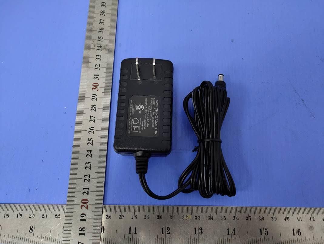
SHENZHEN LCS COMPLIANCE TESTING LABORATORY LTD. FCC ID: 2AQUZ-DR2500 ________________________________________________________________________________ _________ This report shall not be reproduced except in full, without the written approval of Shenzhen LCS Compliance Testing Laboratory Ltd.. Page 1 of 4 External Photos of the EUT Fig.1 Fig.2 SHENZHEN LCS COMPLIANCE TESTING LABORATORY LTD. FCC ID: 2AQUZ-DR2500 ________________________________________________________________________________ _________ This report shall not be reproduced except in full, without the written approval of Shenzhen LCS Compliance Testing Laboratory Ltd.. Page 2 of 4 Fig.3 Fig.4 SHENZHEN LCS COMPLIANCE TESTING LABORATORY LTD. FCC ID: 2AQUZ-DR2500 ________________________________________________________________________________ _________ This report shall not be reproduced except in full, without the written approval of Shenzhen LCS Compliance Testing Laboratory Ltd.. Page 3 of 4 Fig.5 Fig.6 SHENZHEN LCS COMPLIANCE TESTING LABORATORY LTD. FCC ID: 2AQUZ-DR2500 ________________________________________________________________________________ _________ This report shall not be reproduced except in full, without the written approval of Shenzhen LCS Compliance Testing Laboratory Ltd.. Page 4 of 4 Fig.7 Fig.8
ID Label/Location Info
SHENZHEN LCS COMPLIANCE TESTING LABORATORY LTD FCC ID: 2AQUZ-DR2500 This report shall not be reproduced except in full, without the written approval of Shenzhen LCS Compliance Testing Laboratory Ltd. Page 1 of 1 LABEL AND LOCATION Size: L4.0cm*W3.0cm Material: Tagboard Glue: adhesive sticker Font color: White Label color: Black Label Location Workwell Face Recognition Cloud Tablet Time Clock Model No.: DR2500 FCC ID: 2AQUZ-DR2500 This device complies with part 15 of the FCC Rules. Operation is subject to the following two conditions: (1) This device may not cause harmful interference, and (2) this device must accept any interference received, including interference that may cause undesired operation
Internal Photos
SHENZHEN LCS COMPLIANCE TESTING LABORATORY LTD. FCC ID: 2AQUZ-DR2500 ________________________________________________________________________________ _________ This report shall not be reproduced except in full, without the written approval of Shenzhen LCS Compliance Testing Laboratory Ltd.. Page 1 of 6 Internal Photos of the EUT Fig.1 Fig.2 SHENZHEN LCS COMPLIANCE TESTING LABORATORY LTD. FCC ID: 2AQUZ-DR2500 ________________________________________________________________________________ _________ This report shall not be reproduced except in full, without the written approval of Shenzhen LCS Compliance Testing Laboratory Ltd.. Page 2 of 6 Fig.3 Fig.4 SHENZHEN LCS COMPLIANCE TESTING LABORATORY LTD. FCC ID: 2AQUZ-DR2500 ________________________________________________________________________________ _________ This report shall not be reproduced except in full, without the written approval of Shenzhen LCS Compliance Testing Laboratory Ltd.. Page 3 of 6 Fig.5 Fig.6 WIFI Antenna RFID Antenna SHENZHEN LCS COMPLIANCE TESTING LABORATORY LTD. FCC ID: 2AQUZ-DR2500 ________________________________________________________________________________ _________ This report shall not be reproduced except in full, without the written approval of Shenzhen LCS Compliance Testing Laboratory Ltd.. Page 4 of 6 Fig.7 Fig.8 SHENZHEN LCS COMPLIANCE TESTING LABORATORY LTD. FCC ID: 2AQUZ-DR2500 ________________________________________________________________________________ _________ This report shall not be reproduced except in full, without the written approval of Shenzhen LCS Compliance Testing Laboratory Ltd.. Page 5 of 6 Fig.9 Fig.10 SHENZHEN LCS COMPLIANCE TESTING LABORATORY LTD. FCC ID: 2AQUZ-DR2500 ________________________________________________________________________________ _________ This report shall not be reproduced except in full, without the written approval of Shenzhen LCS Compliance Testing Laboratory Ltd.. Page 6 of 6 Fig.11
Operational Description
Workwell Technologies, Inc. 2777 Loker Avenue West, Suite A Carlsbad, California 92010, USA Declaration concerning Antenna Specification Federal Communication Commission Equipment Authorization Division, Application Processing Branch 7435 Oakland Mills Road Columbia, MD 21046 Date: 2020/11/05 TO WHOM IT MAY CONCERN It is hereby declared that the product Model No.: DR2500 FCC ID: 2AQUZ-DR2500 Fulfills the requirement in FCC test relating to the antenna type. The device specified above confirms to the FCC recommendations for Fixed Internal antenna type(s) described below: Antenna No. Model No. of antenna: Type of antenna: Gain of the antenna (Max.) Frequency range: SRD(125kHz) / Internal antenna 0dBi 125kHz 2.4G WLAN / Internal antenna 2.0 dBi 2412MHz-2462 MHz The antenna will be fixed to the radio module by integral connector, and no other antennas not listed above should be used. Sincerely, Name: Cristal Redman/ VP of Product Development Company: Workwell Technologies, Inc. Address: 2777 Loker Avenue West, Suite A Carlsbad, California 92010, USA Phone: (650) 520-4759 Fax: (800) 357-0298 E-Mail: [email protected]
RF Exposure Info
SHENZHEN LCS COMPLIANCE TESTING LABORATORY LTD. FCC ID: 2AQUZ-DR2500 This report shall not be reproduced except in full, without the written approval of Shenzhen LCS Compliance Testing Laboratory Ltd. Page 1 of 4 Maximum Permissible Exposure Report 1. Product Information FCC ID: 2AQUZ-DR2500 Product name Workwell Face Recognition Cloud Tablet Time Clock Test Model DR2500 Power supply For adapter: Input: 100-240V~, 50/60Hz, 0.6A Max Output: DC 12V, 2000mA Operation frequency 2.412-2.462GHz for 2.4G WIFI Antenna Type PIFA Antenna Antenna Gain 2.0 dBi Hardware version / Software version / Channel Number 11 channels for 20MHz bandwidth (2412~2462MHz) Channel Spacing 5MHz Exposure category General population/uncontrolled environment EUT Type Production Unit Device Type Mobile Device 2. Evaluation Method Systems operating under the provisions of FCC 47 CFR section shall be operated in a manner that ensures that the public is not exposed to radio frequency energy level in excess of the Commission’s guidelines. In accordance with 47 CFR FCC Part 2 Subpart J, section 2.1091 this device has been defined as mobile device whereby a distance of 0.2m normally can be maintained between the user and the device, and below RF Permissible Exposure limit shall comply with. In accordance with KDB447498D01 for Simultaneous transmission MPE test exclusion applies when the sum of the MPE ratios for all simultaneous transmitting antennas incorporated in a host device, based on the calculated/estimated, numerically modelled or measured field strengths or power density, is ≤ 1.0. The MPE ratio of each antenna is determined at the minimum test separation distance required by the operating configurations and exposure conditions of the host device, according to the ratio of field strengths or power density to MPE limit, at the test frequency. Either the maximum peak or spatially averaged results from measurements or numerical simulations may be used to determine the MPE ratios. Spatial averaging does not apply when MPE is estimated using simple calculations based on far-field plane-wave equivalent conditions. The antenna installation and operating requirements for the host device must meet the minimum test separation distances required by all antennas, in both standalone and simultaneous transmission operations, to satisfy compliance. 3. Limit 3. 1 Refer Evaluation Method ANSI C95.1–1999: IEEE Standard for Safety Levels with Respect to Human Exposure to Radio Frequency Electromagnetic Fields, 3 kHz to 300 GHz. FCC KDB publication 447498 D01 General 1 RF Exposure Guidance v06: Mobile and Portable Devices RF Exposure Procedures and Equipment Authorization Policies. FCC CFR 47 part1 1.1310: Radiofrequency radiation exposure limits. FCC CFR 47 part2 2.1091: Radiofrequency radiation exposure evaluation: mobile devices SHENZHEN LCS COMPLIANCE TESTING LABORATORY LTD. FCC ID: 2AQUZ-DR2500 This report shall not be reproduced except in full, without the written approval of Shenzhen LCS Compliance Testing Laboratory Ltd. Page 2 of 4 3. 2 Limit Limits for Maximum Permissible Exposure (MPE)/Controlled Exposure Frequency Range(MHz) Electric Field Strength(V/m) Magnetic Field Strength(A/m) Power Density (mW/cm²) Averaging Time (minute) Limits for Occupational/Controlled Exposure 0.3 – 3.0 3.0 – 30 30 – 300 300 – 1500 1500 – 100,000 614 1842/f 61.4 / / 1.63 4.89/f 0.163 / / (100) * (900/f 2 )* 1.0 f/300 5 6 6 6 6 6 Limits for Maximum Permissible Exposure (MPE)/Uncontrolled Exposure Frequency Range(MHz) Electric Field Strength(V/m) Magnetic Field Strength(A/m) Power Density (mW/cm²) Averaging Time (minute) Limits for Occupational/Controlled Exposure 0.3 – 3.0 3.0 – 30 30 – 300 300 – 1500 1500 – 100,000 614 824/f 27.5 / / 1.63 2.19/f 0.073 / / (100) * (180/f 2 )* 0.2 f/1500 1.0 30 30 30 30 30 F=frequency in MHz *=Plane-wave equivalent power density 4. MPE Calculation Method Predication of MPE limit at a given distance Equation from page 18 of OET Bulletin 65, Edition 97-01 S=PG/4πR² Where: S=power density P=power input to antenna G=power gain of the antenna in the direction of interest relative to an isotropic radiator R=distance to the center of radiation of the antenna 5. Antenna Information C2M can only use antennas certificated as follows provided by manufacturer; Internal Identification Antenna type and antenna number Operate frequency band Maximum antenna gain Notes Antenna PIFA Antenna 2400 MHz –5850 MHz 2.0 dBi WiFi Antenna SHENZHEN LCS COMPLIANCE TESTING LABORATORY LTD. FCC ID: 2AQUZ-DR2500 This report shall not be reproduced except in full, without the written approval of Shenzhen LCS Compliance Testing Laboratory Ltd. Page 3 of 4 6. Conducted Power [2.4GWIFI Max Conducted Power] Mode Channel Frequency (MHz) Max Conducted Power(dBm) IEEE 802.11b 1 2412 12.05 6 2437 12.16 11 2462 12.14 IEEE 802.11g 1 2412 12.45 6 2437 12.01 11 2462 11.98 IEEE 802.11n HT20 1 2412 11.95 6 2437 12.13 11 2462 12.19 7. Measurement Results 2.4GWIFI IEEE 802.11b (Peak) Channel Channel 1 Channel 6 Channel 11 Target (dBm) 12.0 12.0 12.0 Tolerance ±(dB) 1.0 1.0 1.0 IEEE 802.11g (Peak) Channel Channel 1 Channel 6 Channel 11 Target (dBm) 12.0 12.0 12.0 Tolerance ±(dB) 1.0 1.0 1.0 IEEE 802.11n HT20 (Peak) Channel Channel 1 Channel 6 Channel 11 Target (dBm) 12.0 12.0 12.0 Tolerance ±(dB) 1.0 1.0 1.0 SHENZHEN LCS COMPLIANCE TESTING LABORATORY LTD. FCC ID: 2AQUZ-DR2500 This report shall not be reproduced except in full, without the written approval of Shenzhen LCS Compliance Testing Laboratory Ltd. Page 4 of 4 8. Evaluation Results As declared by the Applicant, the EUT is a wireless device used in a fix application, at least 20 cm from any body part of the user or nearby persons; from the maximum EUT RF output power, the minimum separation distance, r =20cm, as well as the gain of the used antenna refer to antenna information, the RF power density can be obtained. 2.4GWIFI Band/Mode RF output power Antenna Gain (dBi) MPE (mW/cm2) MPE Limits (mW/cm2) dBm mW I…
Text truncated - open the document above for the full version.
Test Setup Photos
SHENZHEN LCS COMPLIANCE TESTING LABORATORY LTD. FCC ID: 2AQUZ-DR2500 _______________________________________________________________________________________________ This report shall not be reproduced except in full, without the written approval of Shenzhen LCS Compliance Testing Laboratory Ltd.. Page 1 of 2 Test Setup Photos of the EUT Test Setup Photo(s) of Radiated Emissions Measurement Fig. 1 (Below 30MHz) Fig. 2 (30MHz~1GHz) SHENZHEN LCS COMPLIANCE TESTING LABORATORY LTD. FCC ID: 2AQUZ-DR2500 _______________________________________________________________________________________________ This report shall not be reproduced except in full, without the written approval of Shenzhen LCS Compliance Testing Laboratory Ltd.. Page 2 of 2 Test Setup Photo of Line Conducted Emissions Measurement AC Conducted Emission of charge from power adapter mode
Contact Information
Applicant
Cristal Redman(VP of Product Development)
Test Firm
Shenzhen LCS Compliance Testing Laboratory Ltd.Gavin Liang
Technical Specifications
| # | Rule Parts | Frequency Range | Power Output |
|---|---|---|---|
| 1 | 15C | 0.125 MHz - 0.125 MHz | - |
Other Applications from Workwell Technologies, Inc.
2AQUZ-JR2000
Mar 19, 2021Workwell cloud tablet time clock
Equipment Class
DTS - Digital Transmission System