2AQZU-18009CEILING FAN REMOTE CONTROLLER
Satellite Electronic(Zhong Shan)Ltd.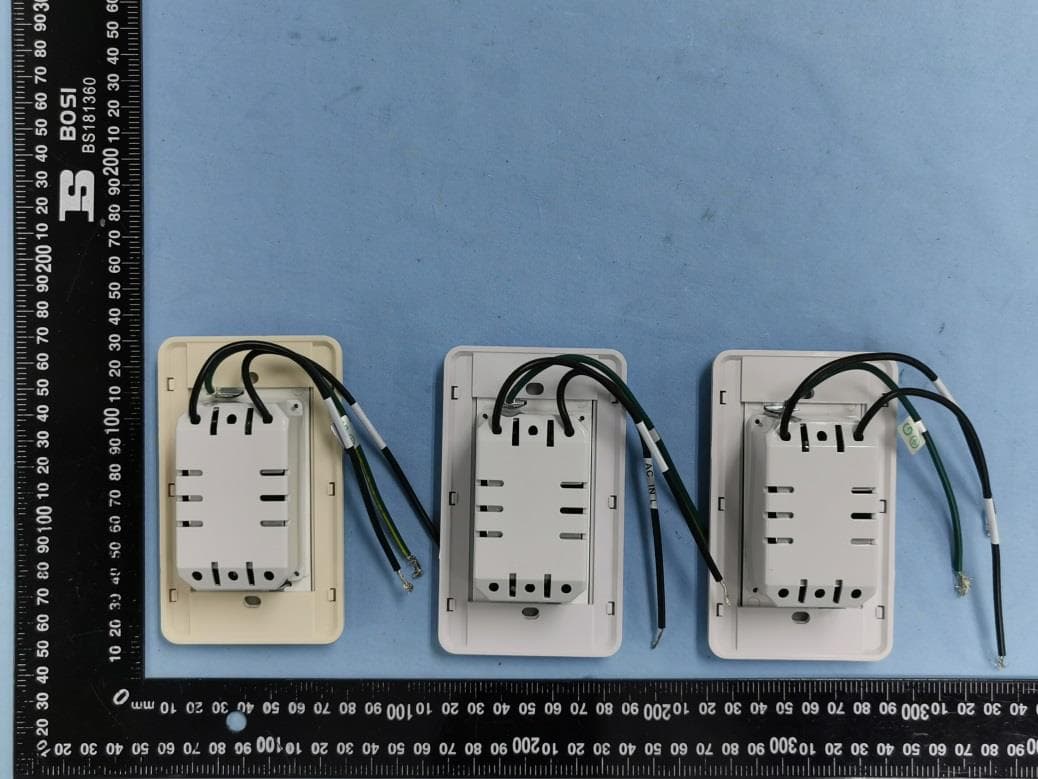
Click to zoom
Application Details
- Equipment Class
- DSC - Part 15 Security/Remote Control Transmitter
- Date of Grant
- Mar 26, 2020
- Application Purpose
- Original Equipment
- Date of Application
- Mar 26, 2020
- Equipment Note
- CEILING FAN REMOTE CONTROLLER
- Frequency Range
- 304.20000000 - 304.20000000
- Country
- China
Documents & Files
Document Text
Text extracted from the exhibit documents filed with the FCC. Open a document above to read the original.
Users Manual
CEILING FAN REMOTE CONTROLLER OPERATION AND INSTALLATION INSTRUCTIONS (Please keep this instruction pamphlet.) IMPORTANT POINTS TO REMEMBER: 1. Read and save these instructions. 2. Please note that all fixed wiring appliances should be installed by a qualified electrician. 3. The supply to the remote control receiver should be connected through a mains switch, i.e. existing wall switch. 4. Disconnect from power supply at wall switch before working on remote control receiver or ceiling fan. 5. Install receiver into the ceiling fan canopy of the fan to ensure proper protection. 6. This unit is to be used for the control of ceiling fan and in an AC110/120V 60Hz power supply only. 7. The receiver is acceptable for installation in damp and wet rated fans, but cannot be submerged in water. The wall transmitter is only to be installed indoors. 8. Do not pull on or cut leads shorter. 9. Do not drop or bump the unit. 10. PLEASE NOTE: The battery will weaken with age and should be replaced before leaking takes place as this will damage the transmitter. Dispose of used battery properly, keep the battery out of reach of children. 11. CAUTION: To reduce the risk of fire or injury, do not use this product in conjunction with any variable (rheostat) wall control. FCC Warning This device complies with Part 15 of the FCC Rules. Operation is subject to the following two conditions: (1) This device may not cause harmful interference, and (2) This device must accept any interference received, including interference that may cause undesired operation. NOTE 1: This equipment has been tested and found to comply with the limits for a Class B digital device, pursuant to part 15 of the FCC Rules. These limits are designed to provide reasonable protection against harmful interference in a residential installation. This equipment generates, uses and can radiate radio frequency energy and, if not installed and used in accordance with the instructions, may cause harmful interference to radio communications. However, there is no guarantee that interference will not occur in a particular installation. If this equipment does cause harmful interference to radio or television reception, which can be determined by turning the equipment off and on, the user is encouraged to try to correct the interference by one or more of the following measures: - Reorient or relocate the receiving antenna. - Increase the separation between the equipment and receiver. - Connect the equipment into an outlet on a circuit different from that to which the receiver is connected. - Consult the dealer or an experienced radio/TV technician for help. NOTE 2: Any changes or modifications to this unit not expressly approved by the party responsible for compliance could void the user's authority to operate the equipment. IMPORTANT YOU MUST SET CEILING FAN MANUAL SWITCH TO HIGH SPEED AND THE LIGHT KIT TO THE ON POSITION BEFORE INSTALLING THE REMOTE CONTROL. . INSTALLATION INSTRUCTIONS 1. Ceiling fan must be set at HIGH speed before installation. 2. Once the connection has been made, the receiver inserts into the drop rod hanging bracket. The canopy comes up to cover the receiver and bracket. AC POWER ON/OFF SWITCH(): Before installing wall control, slide to “OFF” position. After installation is complete, slide to “ON” position to begin operation. Installing Wall Control (TRANSMITTER): Remove wall plate, disconnect and remove the toggle switch from wall junction box. Using the wire connectors, make the electrical connections to the wall control (transmitter) unit. Carefully push all connected wires inside wall switch box. Secure wall control unit with 2 screws previously removed. Face plate will snap onto the transmitter. ACTIVATING THE LEARNING PROCESS 1. After installation is complete, AC power is turned on and SWITCH is at ON position within 30 seconds, press and hold the LEARN button for 3 seconds. Fan will turn on at medium speed and light (if installed) will turn on. This confirms that the SMART SYNC setting is active and ok. (FIG. 4) 2. If user cannot finish the setting within the 30 seconds time frame, the main power must be turned off and re-started again. This will reset the unit. Repeat step 1 until the LEARNING feature is activated as indicated. CAUTION: INCORRECT WIRE CONNECTION WILL DAMAGE THIS RECEIVER. FIG. 4 LIGHT FUNCTION SELECT SWITCH 1. If the ceiling fan has fluorescent lighting, please slide the “light function select switch” to “O” position. If the ceiling fan has incandescent or halogen lighting or LED, please slide the “light function select switch” to “D” position. (FIG. 4) 2. Light load: 190W (Max.) If overloaded, the receiver will cut off light power automatically. Please change the light load. WALL TRANSMITTER OPERATION (FIG. 5) FAN OFF :Turn off the ceiling fan. HI : Turn on the fan at high speed. MED : Turn on the fan at medium speed. LOW: Turn on the fan at low speed. LIGHT: ON/OFF-Turn the light on or off. DIMMER-Press and hold to dim or brighten light to the desired level and release. (Incandescent or halogen or LED and light function select switch Or on “D” position.) REV: Press this button for forward/reverse airflow of ceiling fan. FIG. 5
External Photos
Model: TR269B Report No.: WTG19X12088981W RF Part 15.231a EXHIBIT 2 - EUT EXTERNAL PHOTOGRAPHS Model: TR269B/TR268B/TR267B EUT View 1 EUT View 2 Model: TR269B Report No.: WTG19X12088981W RF Part 15.231a Model: TR269B EUT View 3 EUT View 4 Model: TR269B Report No.: WTG19X12088981W RF Part 15.231a EUT View 5 EUT View 6 Model: TR269B Report No.: WTG19X12088981W RF Part 15.231a EUT View 7 EUT View 8 Model: TR269B Report No.: WTG19X12088981W RF Part 15.231a Model: TR268B EUT View 1 EUT View 2 Model: TR269B Report No.: WTG19X12088981W RF Part 15.231a EUT View 3 EUT View 4 Model: TR269B Report No.: WTG19X12088981W RF Part 15.231a EUT View 5 EUT View 6 Model: TR269B Report No.: WTG19X12088981W RF Part 15.231a Model: TR267B EUT View 1 EUT View 2 Model: TR269B Report No.: WTG19X12088981W RF Part 15.231a EUT View 3 EUT View 4 Model: TR269B Report No.: WTG19X12088981W RF Part 15.231a EUT View 5 EUT View 6
ID Label/Location Info
Model: TR269B Report No.: WTG19X12088981W RF Part 15.231a EXHIBIT 1 - PRODUCT LABELING Proposed FCC ID Label Format FCC ID: 2AQZU-18009 Specifications: Text is black in color and justified. Labels are printed in indelible ink on permanent adhesive silk-screened onto the EUT or shall be affixed at a conspicuous location on the EUT. Proposed Label Location on EUT FCC ID Label Location
Contact Information
Applicant
sean zheng(Manager)
Test Firm
Waltek Testing Group (Shenzhen) Co., Ltd.Jandy So
Technical Specifications
| # | Rule Parts | Frequency Range | Power Output |
|---|---|---|---|
| 1 | 15.231 | 304.2 MHz - 304.2 MHz | - |
Other Applications from Satellite Electronic(Zhong Shan)Ltd.

2AQZU-18085
Sep 10, 2026CEILING FAN REMOTE CONTROL
Equipment Class
DSC - Part 15 Security/Remote Control Transmitter
2AQZU-18083
Aug 24, 2026Ceiling Fan Wall Control
Equipment Class
DXX - Part 15 Low Power Communication Device Transmitter
2AQZU-18073
Dec 04, 2025CEILING FAN REMOTE CONTROL
Equipment Class
DSC - Part 15 Security/Remote Control Transmitter
2AQZU-18071
Nov 27, 2025CEILING FAN REMOTE CONTROL
Equipment Class
DSC - Part 15 Security/Remote Control Transmitter
2AQZU-18075
Nov 27, 2025CEILING FAN REMOTE CONTROL
Equipment Class
DSC - Part 15 Security/Remote Control Transmitter