2AR6I-ZE3221Xzigbee-module
Guangzhou Vensi Intelligent Technology Co., Ltd.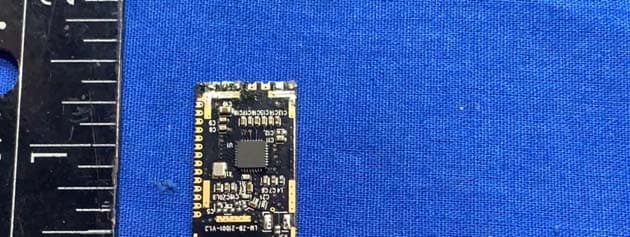
Click to zoom
Application Details
- Equipment Class
- DXX - Part 15 Low Power Communication Device Transmitter
- Date of Grant
- Dec 28, 2020
- Application Purpose
- Original Equipment
- Date of Application
- Dec 27, 2020
- Equipment Note
- zigbee-module
- Frequency Range
- 2405.00000000 - 2480.00000000
- Country
- China
Documents & Files
Document Text
Text extracted from the exhibit documents filed with the FCC. Open a document above to read the original.
Users Manual
Guangzhou Vensi Intelligent Technology Co., Ltd. Professional Supplier Guangzhou Vensi Intelligent Technology Co., Ltd. Technical Specification for Standard ZigBee 3.0 Intelligent Equipment Usage Specification: Only internal technology management and external technology docking specifications. External publication needs to be audited to confirm whether it can be issued. If there is any objection to the content of the document, you can make amendments. versionLM-DEVELOPMENT-R1-20190515 Release time2019-06-11 Guangzhou Vensi Intelligent Technology Co., Ltd. Professional Supplier 1 Technical overview 1.1 Refered code 1.1.1 Home Automation Public Application Profile ¾ Zigbee Profile: 0x0104 ¾ Revision 29 ¾ Version 1.2 1.1.2 ZigBee Cluster Library Specification ¾ Revision 6 ¾ Draft Version 1.0 1.2 Basic description This technical specification is developed according to standard ZHA and maintains compatibility and interoperability with other ZIGBEE. The technical scheme described in this paper adopts EFR32 chip of Silicon labs. The chip supports internal PA and has abundant peripheral hardware resources. 2 Technology list 2.1 Hardware technical parameters main parameter describe Function list Other instructions IC Zigbee module signal intensity PC11 GPIO input Access button EFR32MG21A020F768IM 32-B 20db Guangzhou Vensi Intelligent Technology Co., Ltd. Professional Supplier PB13 GPIO input Switch 1 key PD15 GPIO output Access Indicator PF3 GPIO output Switch indicator 2.2 Technical parameters of software ¾ DEVICE TYPEͧDEVICE IDͨ Alliance-supported device types ¾ Endpoint0x10 3 Man-machine interaction description 3.1 NCP Interactive Mode Communication Sends NCP Control Command to Module by Mobile App Sending Network Command Channel Gateway Gateway Gateway Access mode Use mobile app to join the gateway first, allowing devices to be networked in the gateway off-network mode Select Gateway with Mobile App and Delete the Device 3.2 Switch control operation mode Press panel switch buttonͫPB13 Keyboard input produces a drop edgeͫPF3 The output indicator light is on, indicating that the corresponding control circuit switch Guangzhou Vensi Intelligent Technology Co., Ltd. Professional Supplier has been turned on. If the PF3 output indicator lights up and the indicator lights out, the corresponding control circuit switch is off. 3.3 Status Indicator Whether the gateway has voice prompt to enter the network successfully or not FCC STATEMENT 4. This device complies with Part 15 of the FCC Rules. Operation is subject to the following two conditions: (1) This device may not cause harmful interference. (2) This device must accept any interference received, including interference that may cause undesired operation. 5. any Changes or modifications not expressly approved by the party responsible for compliance could void the user's authority to operate the equipment. NOTE: This equipment has been tested and found to comply with the limits for a Class B digital device, pursuant to Part 15 of the FCC Rules. These limits are designed to provide reasonable protection against harmful interference in a residential installation. This equipment generates uses and can radiate radio frequency energy and, if not installed and used in accordance with the instructions, may cause harmful interference to radio communications. However, there is no guarantee that interference will not occur in a particular installation. If this equipment does cause Guangzhou Vensi Intelligent Technology Co., Ltd. Professional Supplier harmful interference to radio or television reception, which can be determined by turning the equipment off and on, the user is encouraged to try to correct the interference by one or more of the following measures: Reorient or relocate the receiving antenna. Increase the separation between the equipment and receiver. Connect the equipment into an outlet on a circuit different from that to which the receiver is connected. Consult the dealer or an experienced radio/TV technician for help. The MG21-768module is designed to comply with the FCC statement. FCC ID is 2AR6I-ZE3221X The host system using MG21-768, should have label indicated it contain modular’s FCC ID 2AR6I-ZE3221X This radio module must not installed to co-locate and operating simultaneously with other radios in host system , additional testing and equipment authorization may be required to operating simultaneously with other radio. This device complies with Part 15, Subpart C, Section 15.249 of the FCC Rules This module is tested and approved as Limited modular approval with standalone configuration, any OEM incorporated this radio module into any system may require additional testing and evaluation MG21-768integrates a high-performance PCB antenna1. MG21-768uses a u.FL connector2 and requires an external 2.4Ghz antenna. using 2.4GHz 0dBi Terminal Mount Dipole Antenna3. This module is an embedded ZigBee wireless communication module, which supports Zigbee3.0.Using Silicon Labs' EFR32 chip, it is able to build powerful network nodes at a very low total material cost, with leading RF performance. This module is small in size, simple in application, and can be more conveniently embedded into the system. It can help customers shorten the product development cycle, reduce the cost of intelligent equipment renovation, and help customers seize the market more quickly. The DEBUG serial print interface is located below the module and consists of Pin13 Pin18 PIN9. The master IC EFR32Mg21A020F768IM32-B debug interface uses serial port 0 pin Pin13 pin, PA06 (18th pin on the module) and PA05 (19th pin on the module) as data and clock in debug mode respectively Power supply filter circuit, and data line matching resistor as close to the module as possible. The modules should be placed as far as possible away from interference sources, such as WIFI antenna, GSM antenna, DDR CLK, LCD wiring, etc. The area below the module antenna is left empty. Do not lay copper…
Text truncated - open the document above for the full version.
Cover Letter(s)
SCS-F018: Project and Product Certification Representative Authorization Letter Page 1 of 2 Rev 7.0 775 Montague Expressway Milpitas, CA 95035 Tel: 408-526-1188 Fax: 408-526-1088 Email: [email protected] Website: https://www.cps.bureauveritas.com/ Project and Product Certification Representative Authorization Letter Reason for Amendment (current / obsolete) Revision History Approved Date From To Initial Release (obsolete) 1.0 1.0 Nov-14-2006 Revised wording (obsolete) 1.0 2.0 Sept–25-2007 Updated company template (obsolete) 2.0 3.0 Jan-31-2012 Updated letter information (obsolete) 3.0 4.0 May-23-2014 Added FCC ID field (obsolete) 4.0 5.0 Sep-16-2014 Updated company name & logo (current) 5.0 6.0 Jun-27-2018 Updated References and Contact info 6.0 7.0 Aug-30-2020 SCS-F018: Project and Product Certification Representative Authorization Letter Page 2 of 2 Rev 7.0 (Guangzhou Vensi Intelligent Technology Co., Ltd.) (2020-12-07) To: BVCPS, INC. 775 Montague Expressway, Milpitas, CA 95035 USA Dear Sir/Madam, Re: Product Certification Representative Authorization Letter We, _____( Guangzhou Vensi Intelligent Technology Co., Ltd.) _____ hereby authorize Bureau Veritas Consumer Product Services, Inc. to act as a Certification Body for certifying for the following project(s): FCC ID: 2AR6I-ZE3221X Product Description: zigbee-module Model: MG21-768 Sincerely, Client’s signature Client’s name / title zengfanman/manager Contact information / address : No.19 Huangqi Shan Road, Yonghe Development Zone, Whampoa District, Guangzhou
Cover Letter(s)
SCS-F019: Confidentiality Request Letter Page 1 of 2 Rev 7.0 775 Montague Expressway Milpitas, CA 95035 Tel: 408-526-1188 Fax: 408-526-1088 Email: [email protected] Website: https://www.cps.bureauveritas.com/ Confidentiality Request Letter Reason for Amendment (current / obsolete) Revision History Approved Date From To Initial Release (obsolete) 1.0 1.0 Nov-14-2006 Adding CFR 2.459 (obsolete) 1.0 2.0 August – 11 - 2008 Updated company template & Added text box (obsolete) 2.0 3.0 Jan-31-2012 Added IC confidentiality letter form (obsolete) 3.0 4.0 March-26-2015 Corrections to STC form. Added reference to KDB (obsolete) 4.0 5.0 Nov-19-2015 Updated company logo (current) 5.0 6.0 Jun-26-2019 Updated References and Contact Info 6.0 7.0 Aug-30-2020 SCS-F019: Confidentiality Request Letter Page 2 of 2 Rev 7.0 (Guangzhou Vensi Intelligent Technology Co., Ltd.) (2020-12-07) To: Federal Communications Commission Authorization and Evaluation Division 7435 Oakland Mills Road Columbia, MD 21046-1609 Cc: Bureau Veritas Consumer Products Services Inc. 775 Montague Expressway Milpitas, CA 95035 Subject: Confidentiality Request for FCC ID: 2AR6I-ZE3221X Pursuant to CFR 47 sections 0.457 and 0.459, we respectfully request permanent confidential treatment of the following Exhibits accompanying this application be held confidential: Type of Confidentiality Requested Exhibit Short Term Permanent Block Diagram Short Term Permanent Operational Description/ Theory of Operation Short Term Permanent Schematics The above materials contain trade secrets and proprietary information not customarily released to the public. The public disclosure of these materials may be harmful to the applicant and provide unjustified benefits to its competitors. Permanent Confidentiality: The applicant requests the exhibits listed above as permanently confidential be permanently withheld from public review due to materials that contain trade secrets and proprietary information not customarily released to the public. The applicant understands that disclosure of this application and all accompanying documentation will not be made before the date of the Grant for this application. Sincerely, Client’s signature: Client’s name & title: zengfanman/manager Contact information / address: No.19 Huangqi Shan Road, Yonghe Development Zone, Whampoa District, Guangzhou
Cover Letter(s)
SCS-F26 Modular Approval Letter Page 1 of 3 Rev 12.0 775 Montague Expressway Milpitas, CA 95035 Tel: 408-526-1188 Fax: 408-526-1088 Email: [email protected] Modular Approval Declaration Letter Reason for Amendment (current / obsolete) Revision History Approved Date From To Initial Release (Obsolete) 1.0 1.0 Dec-04-2006 Added IC Modular Letter (Obsolete) 1.0 2.0 Feb 16 2009 Add LMA and MA option (Obsolete) 2.0 3.0 April 14 2010 Revised per RSS Gen issue 3.0 (Obsolete) 3.0 4.0 Jan 12 2011 Removed Foot(2) (obsolete) 4.0 5.0 July 19 2011 Adding New note per KDB996369 D01 V01R03 (obsolete) 5.0 6.0 August 29 2011 Updated company template & Added text box (obsolete) 6.0 7.0 Jan-31-2012 Updated modular requirement (obsolete) 7.0 8.0 Sept 05 2014 Updated template to meet RSP 100 issue 10 (obsolete) 8.0 9.0 Nov 20 2014 Updated template to meet RSP 100 issue 11 (obsolete)) 9.0 10.0 March 19 2015 Revised the Modular Requirement statements (obsolete) 10.0 11.0 July 28, 2016 Updated template with BV logo (current) 11.0 12.0 June 26, 2019 SCS-F26 Modular Approval Letter Page 2 of 3 Rev 12.0 (Guangzhou Vensi Intelligent Technology Co., Ltd.) (Date) 2020-12-28 (Product name) FCC ID: 2AR6I-ZE3221X , is seeking FCC Authorization as a Single Modular Transmitter / Single Limited Modular Transmitter (Please check one) The EUT meets the requirements for Single Modular Approval / Single Limited Modular Approval (Please check one) as detailed in KDB 996369. Compliance to each of the requirements is described below: Item Modular requirement Yes No Please provide a detailed explanation if the answer is “No.” 1 Have its own RF shielding No Products belong to restricted modules rather than full module certification 2 Have buffered modulation/data inputs (if such inputs are provided) YES 3 The modular transmitter must have its own power supply regulation. YES 4 Meet the antenna requirements of section 15.203 YES 5 Be tested in a stand-alone configuration, i.e., the antenna, AC or DC power and data input/output lines must be connected to the module but, the module must not be inside another case during testing. YES 6 Be labeled with its own FCC ID number, and if the FCC ID is not visible when the module is installed inside another device, then the outside of the device into which the module is installed must also display a label referring to the enclosed module. YES 7 The modular transmitter is manufactured so that the user can not influence the operation of the transmitter that will operate outside of the scope of the regulations. YES 8 Address compliance with the Commission`s RF exposure limits in Sections 1.1310 and 2.1093. YES Note: (1) LMA may be granted when one or more of the requirements in the table above cannot be demonstrated. LMA will also be issued in those instances where applicants can demonstrate that they will retain control over the final installation of the device, such that compliance of the end product is assured. In such cases, an operating condition on the LMA for the module must state that the module is only approved for use when installed in devices produced by a specific manufacturer. When LMA is sought, the application for equipment certification must specifically state how control of the end product into which the module will be installed, and will be maintained, such that full compliance of the end product is always ensured. (2) Please provide Clear and specific instructions describing the conditions, limitations and procedures for third-parties to use and/or integrate the module into a host device. (3) For non-Software Defined Radio transmitter modules where software is used to ensure compliance of the device, technical description of how such control is implemented to ensure prevention of third party modification must be provided (see KDB 594280). Note 1: Compliance of a module in its final configuration is the responsibility of the applicant. A host device will not be considered certified if the instructions regarding antenna configuration provided in the original description, of one or more separately certified modules it contains, were not followed. Example: A separately certified low-power transceiver module using Bluetooth technology which is housed in a desktop computer, laptop or peripheral does not require the overall system to be recertified, if the desktop computer, laptop or peripheral, as a stand-alone unit, complies with all applicable technical standards. Client’s signature Client’s name & title: zengfanman/manager Contact information / address: No.19 Huangqi Shan Road, Yonghe Development Zone, Whampoa District, Guangzhou SCS-F26 Modular Approval Letter Page 3 of 3 Rev 12.0 (Guangzhou Vensi Intelligent Technology Co., Ltd.) LMA Declaration Letter We, (applicant name), declare that we will retain control over the final installation of the device, (FCC ID: 2AR6I-ZE3221X ) so that compliance of the end product is assured. In such cases, an operating condition on the LMA for the module must be only approved for use when installed in devices produced by a specific manufacturer. Client’s signature Client’s name & title: zengfanman/manager Contact information / address: No.19 Huangqi Shan Road, Yonghe Development Zone, Whampoa District, Guangzhou
External Photos
Report No.: CQASZ2020120004EX-01 Page:32 of 34 6.2 EUT Constructional Details Report No.: CQASZ2020120004EX-01 Page:33 of 34
ID Label/Location Info
Label Location
Internal Photos
Report No.: CQASZ2020120004EX-01 Page:32 of 34 6.2 EUT Constructional Details Report No.: CQASZ2020120004EX-01 Page:33 of 34 Report No.: CQASZ2020120004EX-01 Page:34 of 34 END OF THE REPORT
Test Report
Shenzhen Huaxia Testing Technology Co., Ltd 1F., Block A of Tongsheng Technology Building, Huahui Road, Dalang Street, Longhua District, Shenzhen, China Telephone: +86-755-26648640 Fax: +86-755-26648637 Website: www.cqa-cert.com Report Template Version: V04 Report Template Revision Date: 2018-07-06 Test Report The test report is effective only with both signature and specialized stamp, The result(s) shown in this report refer only to the sample(s) tested. Without written approval of CQA, this report can’t be reproduced except in full. Report No. : CQASZ20201200041EX-01 Applicant: Guangzhou Vensi Intelligent Technology Co., Ltd. Address of Applicant: No.19 Huangqi Shan Road, Yonghe Development Zone, Whampoa District, Guangzhou Manufacturer: Guangzhou Vensi Intelligent Technology Co., Ltd. Address of Manufacturer: No.19 Huangqi Shan Road, Yonghe Development Zone, Whampoa District, Guangzhou Equipment Under Test (EUT): Product: zigbee-module Model No.: MG21-768 Brand Name: FCC ID: 2AR6I-ZE3221X Standards: 47 CFR Part 15, Subpart C Date of Test: 2020-11-10 to 2020-11-30 Date of Issue: 2020-12-11 Test Result : PASS* *In the configuration tested, the EUT complied with the standards specified above Tested By: (Jun Li) Reviewed By: (Aaron Ma) Approved By: ( Jack Ai) Shenzhen Huaxia Testing Technology Co., Ltd Report No.: CQASZ20201200041EX-01 Page:2 of 34 1 Version Revision History Of Report Report No. Version Description Issue Date CQASZ20201200041EX-01 Rev.01 Initial report 2020-12-11 Report No.: CQASZ20201200041EX-01 Page:3 of 34 2 Test Summary Test Item Test Requirement Test method Result Antenna Requirement 47 CFR Part 15, Subpart C Section 15.203 ANSI C63.10 (2013) PASS AC Power Line Conducted Emission 47 CFR Part 15, Subpart C Section 15.207 ANSI C63.10 (2013) PASS Field Strength of the Fundamental Signal 47 CFR Part 15, Subpart C Section 15.249 (a) ANSI C63.10 (2013) PASS Spurious Emissions 47 CFR Part 15, Subpart C Section 15.249 (a)/15.209 ANSI C63.10 (2013) PASS Restricted bands around fundamental frequency (Radiated Emission) 47 CFR Part 15, Subpart C Section 15.249(a)/15.205 ANSI C63.10 (2013) PASS 20dB Occupied Bandwidth 47 CFR Part 15, Subpart C Section 15.215 (c) ANSI C63.10 (2013) PASS Report No.: CQASZ20201200041EX-01 Page:4 of 34 3 Contents Page 1 VERSION .................................................................................................................................................................. 2 2 TEST SUMMARY .................................................................................................................................................... 3 3 CONTENTS .............................................................................................................................................................. 4 4 GENERAL INFORMATION ................................................................................................................................... 5 4.1 CLIENT INFORMATION ............................................................................................................................................ 5 4.2 GENERAL DESCRIPTION OF EUT ............................................................................................................................. 5 4.3 TEST ENVIRONMENT AND MODE ............................................................................................................................ 7 4.4 DESCRIPTION OF SUPPORT UNITS ........................................................................................................................... 7 4.1 TEST LOCATION ...................................................................................................................................................... 7 4.2 TEST FACILITY ........................................................................................................................................................ 7 4.3 STATEMENT OF THE MEASUREMENT UNCERTAINTY ................................................................................................ 7 4.4 DEVIATION FROM STANDARDS ............................................................................................................................... 8 4.5 ABNORMALITIES FROM STANDARD CONDITIONS .................................................................................................... 8 4.6 OTHER INFORMATION REQUESTED BY THE CUSTOMER .......................................................................................... 8 4.7 EQUIPMENT LIST..................................................................................................................................................... 9 5 TEST RESULTS AND MEASUREMENT DATA .............................................................................................. 10 5.1 ANTENNA REQUIREMENT ..................................................................................................................................... 10 5.2 CONDUCTED EMISSIONS ....................................................................................................................................... 11 5.3 RADIATED EMISSION ............................................................................................................................................ 15 5.4 20DB BANDWIDTH ............................................................................................................................................... 27 6 PHOTOGRAPHS ................................................................................................................................................... 30 6.1 RADIATED EMISSION TEST SETUP ......................................................................................................................... 30 6.1 CONDUCTED EMISSION TEST SETUP ..................................................................................................................... 31 6.2 EUT CONSTRUCTIONA…
Text truncated - open the document above for the full version.
Test Setup Photos
Report No.: CQASZ2020120004EX-01 Page:30 of 34 6 Photographs 6.1 Radiated Emission Test Setup 9KHz~30MHz 30MHz~1GHz: Report No.: CQASZ2020120004EX-01 Page:31 of 34 Above 1GHz: 6.1 Conducted Emission Test Setup 9KHz~30MHz
Contact Information
Applicant
Fan Man Zeng
Test Firm
Shenzhen Huaxia Testing Technology Co., LtdJack Ai
[email protected]+8613902988375
Technical Specifications
| # | Rule Parts | Frequency Range | Power Output |
|---|---|---|---|
| 1 | 15C | 2.40 GHz - 2.48 GHz | - |