2AR7VF-9788BLE Module
XIAMENSHI C-CHIP Co., Ltd.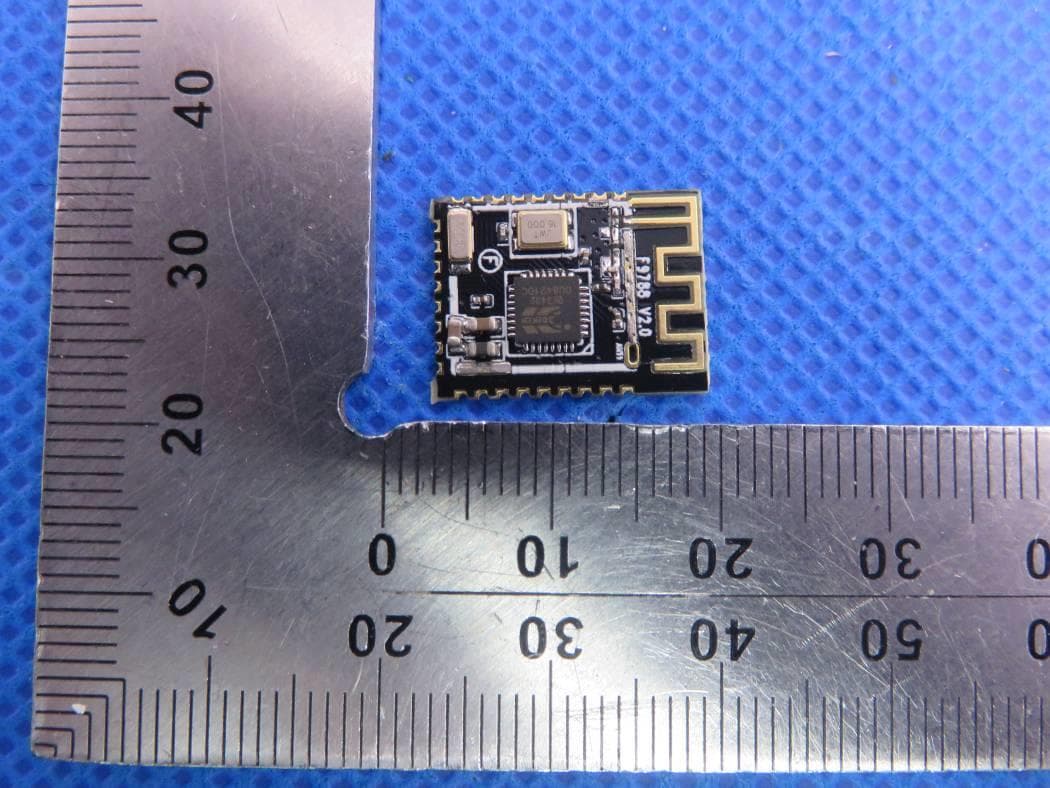
Click to zoom
Application Details
- Equipment Class
- DTS - Digital Transmission System
- Date of Grant
- Apr 21, 2020
- Application Purpose
- Original Equipment
- Date of Application
- Apr 21, 2020
- Equipment Note
- BLE Module
- Frequency Range
- 2402.00000000 - 2480.00000000
- Company
- XIAMENSHI C-CHIP Co., Ltd.
- Country
- China
Documents & Files
Document Text
Text extracted from the exhibit documents filed with the FCC. Open a document above to read the original.
Users Manual
Specification Product name : Bluetooth module Product model:F-9788 Document No: Document Version:V1.1 File include (C-CHIP) confidential documents, without permission, can not be disclosed 1.Product overview: F-9788 V2.0 is a cost-effective Bluetooth module using BK3432_QFN32 chip to support Bluetooth V5.0, with ARM968E built-in kernel and 20K RAM. It can support Bluetooth long distance, big data features and SIGmesh.The module provides all bluetooth ® low power features 5.0: broadcast, stack, customer application profile, and application space, so no external processor is required.The module also provides a flexible hardware interface to connect the sensors.The module can be directly powered by a standard 3V coin battery or a pair of AAA batteries.In the lowest power sleep mode, it consumes only 1.6uA(no RAM reserved and external interrupts enabled) and wakes up in hundreds of microseconds.After purchasing bluetooth ® module, we provide free technical support for Android application iOS system or application system. Edit Review Approve 2.Application area: The module is mainly used for wireless network communication, the main applications include: location tags, asset tracking, sports and fitness sensors, medical sensors, smart watches, remote controls, toys, light etc. ※ Mobile phone accessories ※ Sports and health equipment ※ Health care and medical equipment ※ Family and building automation ※ Consumer electronics 4.performance parameter: Model F-9788 Bluetooth specification Bluetooth V5.0 Service voltage DC1.2V-3.6V B l u e t o o t h P r o f i l e ATT,GATT,SMP,L2CAP,GAP Supply voltage ≤10mA Standby current <500uA Temperature range -20ºC to +105ºC The wireless transmission range 0~100(meter) Frequency range 2.402GHz-2.480GHz The external interface SPI, UART, GPIO,I2C Module size 26.0*14.5 *2mm 5.Module block diagram: 6.The size of the module graph: 7.Device pin out diagram: 8.Pin definition: 9.Design notes: I n o r d e r t o b e t t e r S N R , p l e a s e p a y a t t e n t i o n t o t h e h a r d w a r e d e s i g n o f PA , D C b o o s t e r, D C / D C c i r c u i t a n d t h e m o d u l e p o w e r c i r c u i t t o a v o i d i n f l u e n c i n g m o d u l e . 10.N o t e: A.T h e s i g n a l s t r e n g t h i s d e p e n d i n g o n t h e e n v i r o n m e n t o f B l u e t o o t h a p p l i c a t i o n , s u ch a s w o o d a n d m e t a l w i l l b l o c k t h e t r a n s m i s s i o n s i g n a l t o g e t t h e s h o r t e r t r a n sm i s s i o n d i s t a n c e . B.B e c a u s e o f m e t a l w i l l b l o c k t h e s i g n a l t r a n s m i s s i o n , i t i s r e c o m m e n d n o t t o u s i n g t h e m e t a l h o u s i n g . C.P C B l a y o u t g u i d e l i n e : n o a n y c o p p e r e x i s t e d i n t h e a nt e n n a a r e a o f t h e m o d u l e i s t h e P C B a n t e n n a , t h e m e t a l w i l l w e a k e n t h e f u n c t i o n o f t h e a n t e n n a w h e n t h e a n t e n n a m o d u l e t o t h e m o d u l e b o a r d , f o l l o w i n g p r o h i b i t e d p a v i n g a n d w a l k t h e l i n e . D. If the module antenna next to the battery、 metal, liquid crystal screen, loudspeaker, at least keep them away from antenna distance 15mm E. When layout the power supply line recommended star line, and to ensure that the Bluetooth module Power supply lines is better , and BT should be with the amplifier, power amplifier, MCU, separately, and the underside of the BT has no other interference. F. suggests the module antenna part floating on the floor, do not go around the antenna control line, power line, audio line, MIC interference lines; G. If the module antenna near the row seats, Because of metal will block the signal transmission, it is recommended to use professional high-gain antenna. 11.Recommended reflow temperature: Key features of the profile: -Initial Ramp=1-2.5°C/sec to 175°C equilibrium -Equilibrium time=60 to 80 seconds -Ramp to Maximum temperature (250°C)=3°C/sec Max -Time above liquidus temperature(217°C): 45 - 90 seconds -Device absolute maximum reflow temperature: 250°C 12.Application schematic diagram: Reference schematic diagram for reference purposes only! (OEM) Integrator has to assure compliance of the entire end-product incl. the integrated RF Module. For 15 B (§15.107 and if applicable §15.107) compliance, the host manufacturer is required to show compliance with 15 while the module is installed and operating. Furthermore the module should be transmitting and the evaluation should confirm that the module's intentional emissions (15C) are compliant (fundamental / out-of-band). Finally the integrator has to apply the appropriate equipment authorization (e.g. Verification) for the new host device per definition in §15.101. Integrator is reminded to assure that these installation instructions will not be made available to the end user of the final host device. The final host device, into which this R - F Module isintegrated" hasto be labelled with an auxilliary lable stating the FCC IDofthe RF Module, such as "Contains FCC ID: "This device complies with part 15 of the FCC rules. Operation is subject to the following two conditions: (1) this devicemay not cause harmful interference, and (2) this devicemust accept any interference received, including interference thatmay cause undesired operation." NOTE: This equipment has been tested and found to comply with the limits for a Class B digital device, pursuant to part 15 of the FCC Rules. These limits are designed to provide reasonable protection against harmful interference in a residential installation. This equipment generates, uses and can radiate radio frequency energy and, if not installed and used in accordance with the instructions, may cause harmful interference to radio communications. However, there is no guarantee that interference will not occur in a particular installation. If this equipment does cause harmful interference to radio or television reception, which can be determined…
Text truncated - open the document above for the full version.
Cover Letter(s)
RE FCC ID: 2AR7VF-9788 To the certification reviewer: We are hereby applying for full modular approval of the above-referenced FCC ID, based on compliance with all of the criteria as detailed below. Sincerely, Jing Gong Part 15 Unlicensed Single Modular Transmitter Approval Justification per 15.212 Requirement per 15.212 reference (i) The radio elements of the modular transmitter must have their own RF shielding. Shielding is provided by a metal cover over the circuitry. (ii) The modular transmitter must have buffered modulation/data inputs (if such inputs are provided. All modulation and data inputs are buffered by circuitry on the transmitter chip. (iii) The modular transmitter must have its own power supply regulation. Power supply regulation is provided by circuitry on the transmitter chip. (iv) The modular transmitter must comply with the antenna and transmission system requirements of §§ 15.203, 15.204(b) and 15.204(c). The antenna is permanently attached. (v) The modular transmitter must be tested in a stand-alone configuration, i.e., the module must not be inside another device during testing for compliance with Part 15 parameters. Testing was performed with the module extended outside of the host on a special extender board, as shown in the test setup photos. / Testing was performed in a stand-alone configuration as shown in the test setup photos. (vi) The modular transmitter must be equipped with either a permanently affixed label or must be capable of electronically displaying its FCC identification number. If the FCC ID is not visible when the module is installed inside another device, then the outside of the device into which the module is installed must also display a label referring to the enclosed module. A sample of the host label is provided as an exhibit, showing the FCC identifier of the module. (vii) The modular transmitter must comply with any specific rules or operating requirements that ordinarily apply to a complete transmitter and the manufacturer must provide adequate instructions along with the module to explain any such requirements. A copy of these instructions must be included in the application for equipment authorization. The module complies fully with the operating requirements of Part 15 section [...] as demonstrated in the test report exhibit. (viii) The modular transmitter must comply with any applicable RF exposure requirements in its final configuration. This module operates under Part 15 section [15.249], which s exempt from RF exposure evaluation owing to the very low operating power:
ID Label/Location Info
FCC ID Label Location FCC ID: 2AR7VF-9788
Internal Photos
Internal Photos OPEN VIEW OF EUT INTERNAL VIEW OF EUT-1 Antenna INTERNAL VIEW OF EUT-2 VIEW OF EUT-3
Operational Description
Declaration concerning Antenna Specification It is hereby declared that the product Model No.: F-9788 FCC ID: 2AR7VF-9788 fulfills the requirement in FCC test relating to the antenna type. XIAMENSHI C-CHIP Co., Ltd.The device specified above confirms to the FCC recommendations for internal antenna type(s) described below: Type of antenna: PCB Antenna Gain of the antenna: 0 dBi Frequency range: 2402-2480 MHz The mounting of the antenna is fixed to the radio module and no other antenna should be used. Company name: XIAMENSHI C-CHIP Co., Ltd. Address: 1008 Guanyinshan, Operating Center, Siming District, Xiamen, China Place: Xiamen Date: 2020-04-07 Signature:
RF Exposure Info
RF EXPOSURE EVALUATION 1. PRODUCT INFORMATION Product Description BLE Module Model Name F-9788 FCC ID 2AR7VF-9788 2. EVALUATION METHOD According to 447498 D01 General RF Exposure Guidance v05 The 1-g and 10-g SAR test exclusion thresholds for 100 MHz to 6 GHz at test separation distances ≤ 50 mm are determined by: [(max. power of channel, including tune-up tolerance, mW)/(min. test separation distance, mm)] ·[√f(GHz)] ≤ 3.0 for 1-g SAR and ≤ 7.5 for 10-g extremity SAR. Where f(GHz) is the RF channel transmit frequency in GHz Power and distance are rounded to the nearest mW and mm before calculation 3. CALCULATION P t = 2.477dBm=1.77mW The value of the Maximum output power P t is referred to the test report of the CFR47 §15.247. The result for RF exposure evaluation SAR=(1.77mW /5mm) .[√2.402GHz)]= 0.55<3.0 for 1-g SAR and ≤ 7.5 for 10-g extremity SAR. 4. CONCLUSION The SAR evaluation is not required.
Test Report
Page 1 of 47 FCC Test Report Report No.: AGC07133200101FE02 FCC ID : 2AR7VF-9788 APPLICATION PURPOSE : Original Equipment PRODUCT DESIGNATION : BLE Module BRAND NAME : C-chip MODEL NAME : F-9788 APPLICANT : XIAMENSHI C-CHIP Co., Ltd. DATE OF ISSUE : Apr. 02, 2020 STANDARD(S) : FCC Part 15.247 REPORT VERSION : V1.0 Attestation of Global Compliance (Shenzhen) Co., Ltd CAUTION: This report shall not be reproduced except in full without the written permission of the test laboratory and shall not be quoted out of context. Report No.: AGC07133200101FE02 Page 2 of 47 REPORT REVISE RECORD Report Version Revise Time Issued Date Valid Version Notes V1.0 / Apr. 02, 2020 Valid Initial Release Report No.: AGC07133200101FE02 Page 3 of 47 TABLE OF CONTENTS 1. VERIFICATION OF COMPLIANCE ............................................................................................................... 5 2. GENERAL INFORMATION ............................................................................................................................ 6 2.1. PRODUCT DESCRIPTION .................................................................................................................... 6 2.2.TABLE OF CARRIER FREQUENCYS .................................................................................................... 6 2.3. RELATED SUBMITTAL(S)/GRANT(S) ................................................................................................... 7 2.4.TEST METHODOLOGY .......................................................................................................................... 7 2.5. SPECIAL ACCESSORIES ..................................................................................................................... 7 2.6. EQUIPMENT MODIFICATIONS ............................................................................................................. 7 3. MEASUREMENT UNCERTAINTY ................................................................................................................. 8 4. DESCRIPTION OF TEST MODES ................................................................................................................. 9 5. SYSTEM TEST CONFIGURATION ............................................................................................................. 10 5.1 CONFIGURATION OF TESTED SYSTEM ............................................................................................ 10 5.2. EQUIPMENT USED IN TESTED SYSTEM .......................................................................................... 10 5.3. SUMMARY OF TEST RESULTS .......................................................................................................... 10 6. TEST FACILITY ............................................................................................................................................ 11 7. PEAK OUTPUT POWER ............................................................................................................................. 12 7.1. MEASUREMENT PROCEDURE .......................................................................................................... 12 7.2. TEST SET-UP (BLOCK DIAGRAM OF CONFIGURATION) ................................................................. 12 7.3. LIMITS AND MEASUREMENT RESULT .............................................................................................. 13 8. 6 DB BANDWIDTH ...................................................................................................................................... 15 8.1. MEASUREMENT PROCEDURE .......................................................................................................... 15 8.2. TEST SET-UP (BLOCK DIAGRAM OF CONFIGURATION) ................................................................. 15 8.3. LIMITS AND MEASUREMENT RESULTS ........................................................................................... 15 9. CONDUCTED SPURIOUS EMISSION ........................................................................................................ 17 9.1. MEASUREMENT PROCEDURE .......................................................................................................... 17 9.2. TEST SET-UP (BLOCK DIAGRAM OF CONFIGURATION) ................................................................. 17 9.3. MEASUREMENT EQUIPMENT USED ................................................................................................ 17 9.4. LIMITS AND MEASUREMENT RESULT .............................................................................................. 17 10. MAXIMUM CONDUCTED OUTPUT POWER SPECTRAL DENSITY ....................................................... 22 10.1. MEASUREMENT PROCEDURE ........................................................................................................ 22 10.2. TEST SET-UP (BLOCK DIAGRAM OF CONFIGURATION) ............................................................... 22 10.3. MEASUREMENT EQUIPMENT USED .............................................................................................. 22 10.4. LIMITS AND MEASUREMENT RESULT ............................................................................................ 22 11. RADIATED EMISSION ............................................................................................................................... 24 Report No.: AGC07133200101FE02 Page 4 of 47 11.1. MEASUREMENT PROCEDURE ........................................................................................................ 24 11.2. TEST SETUP ..................................................................................................................................... 25 11.3. LIMITS AND MEASUREMENT RESULT ............................................................................................ 26 11.4. TEST RESULT ...........................................................................................................…
Text truncated - open the document above for the full version.
Test Setup Photos
Test Setup Photos CONDUCTED EMISSION TEST SETUP RADIATED EMISSION TEST SETUP BELOW 1GHZ RADIATED EMISSION TEST SETUP ABOVE 1GHZ CONDUCTED TEST SETUP
Contact Information
Applicant
Jing Gong
Test Firm
Attestation of Global Compliance (Shenzhen) Co., LDoris Li
[email protected]+86-755-25234088
Technical Specifications
| # | Rule Parts | Frequency Range | Power Output |
|---|---|---|---|
| 1 | 15C | 2.40 GHz - 2.48 GHz | 1.80 mW |
Other Applications from XIAMENSHI C-CHIP Co., Ltd.
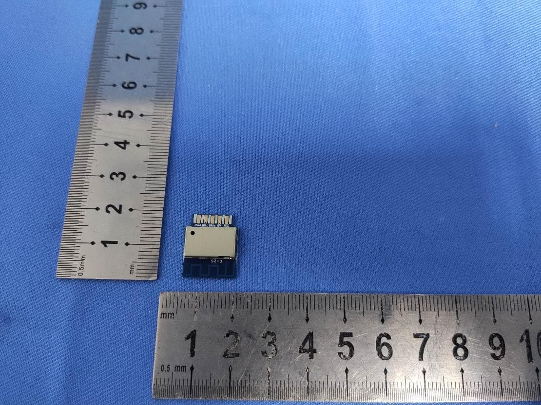
2AR7VC-2S
Jun 07, 2021Bluetooth Module and 2.4G WIFI Module
Equipment Class
DTS - Digital Transmission System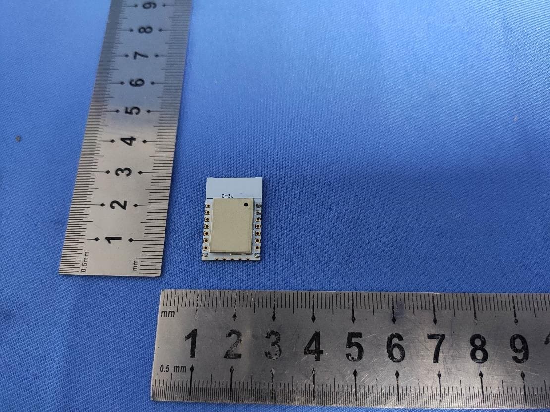
2AR7VC-3L
Jun 05, 2021Bluetooth module and 2.4G wifi module
Equipment Class
DTS - Digital Transmission System