2ARMP-9308RADIO-CONTROLLED WEATHER STATION WITH 3 OUTDOOR SENSORS
Digi-Max Technology Limited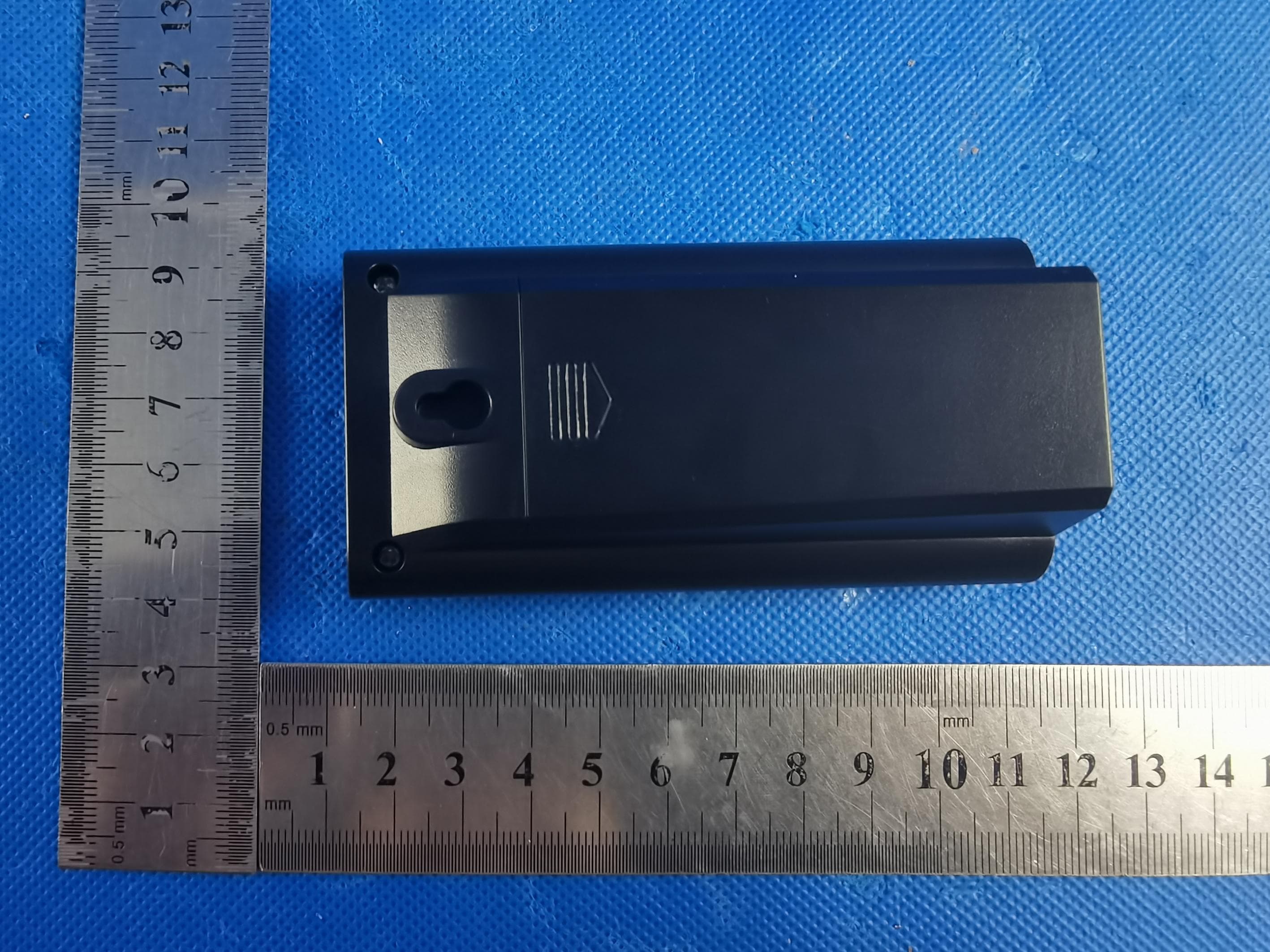
Click to zoom
Application Details
- Equipment Class
- DSC - Part 15 Security/Remote Control Transmitter
- Date of Grant
- May 23, 2023
- Application Purpose
- Original Equipment
- Date of Application
- May 23, 2023
- Equipment Note
- RADIO-CONTROLLED WEATHER STATION WITH 3 OUTDOOR SENSORS
- Frequency Range
- 433.92000000 - 433.92000000
- Company
- Digi-Max Technology Limited
- Country
- China
Documents & Files
Document Text
Text extracted from the exhibit documents filed with the FCC. Open a document above to read the original.
Users Manual
Thank you for purchasing our product. This instruction manual is part of the product and is designed to provide you with important information regarding the safe and proper use of the product. Please read this manual carefully before using the product and keep it handy for future reference. Please use the product only as described and for its intended purposes. INTENDED USE 3 This electronic appliance is intended for time, humidity and temperature display and the described additional features. Any other use or modification of the electronic appliance does not comply with the intended uses. The manufacturer is not liable for damages caused by improper use or misuse. PRODUCT DESIGN OVERVIEW Display 1. Time display 2. Snooze symbol 3. Low battery indicator of main station 4. Alarm sound symbol 5. Radio tower symbol 6. Day of the week 7. Date (day / month) 8.Indoor comfort level display 9. Temperature display of main station 10. Temperature trend symbol of main station 11. MAX/MIN symbol of main station 12. Humidity trend symbol of main station 13. Humidity display of main station 14. Barometer display 15. Weather icon 16. Barometer trend symbol RADIO-CONTROLLED WEATHER STATION WITH 3 OUTDOOR SENSORS Model:9308 17. Low temperature warning 18. Channel 1, 2, 3 reception 19. Channel 1, 2, 3 temperature trend 20. Channel 1, 2, 3 reception icon 21. Sensor 1, 2, 3 low battery indication 22. Channel 1, 2, 3 MAX/MIN symbol 23. Channel 1, 2, 3 humidity trends 24. Channel 1, 2, 3 humidity display 25. Channel 1, 2, 3 temperature display 26. Room name (senor 1, 2, 3) 27. Channel 1, 2, 3 comfort level indicator 28. Hole for wall mounting 29. Battery compartment 30. Stand 31. Type C Interface 32. DOWN button 33. UP button 34. ROOM 3 button 35. ROOM 2 button 36. ROOM 1 button 37. Pressure button 38. SET button 39. SNOOZE/LIGHT button 40. Battery compartment cover 4 5 Outdoor Sensor 41. Temperature display 42. Humidity display 43. Selected channel 44. LED operating indicator 45. °C/°F button 46. TX button 47. Hole for wall mounting 48. Channel selection switch 49. Battery compartment 50. Battery compartment cover TECHNICAL DATA Main Station Temperature measurement range: 0°C to 50°C 32°F to 122°F Humidity measurement range: 20% to 95% Radio-controlled clock: WWVB (US) / DCF77 (DE) Frequency band: 60 kHZ (WWVB) / 77.5 kHZ (DCF77) Batteries: 3 x 1.5V R03/LR03 (size AAA) Main Adapter Input voltage: 100-240V~ Input AC frequency: 50/60Hz Output voltage: 5.0V Output current: 1.0A Output power: 5.0W 414243444546 474849 50 6 Outdoor Sensor Temperature measurement range: -40°C to 60°C -40°F to 140°F Humidity measurement range: 20% to 95% Wireless range: max. 100m (open area, no obstacles) Batteries: 2 x 1.5V R03/LR03 (size AAA) Waterproof level: IPX4 SCOPE OF DELIVERY 1 Main station 3 Outdoor sensors 1 Power cable 1 Set of operating instructions 4 Screws 4 Dowels SAFETY INSTRUCTIONS Important Safety Information for Users WARNING! RISK OF INJURY! Persons lacking physical, sensory or mental abilities or lack of experience and knowledge should be supervised or instructed by the person who knows the safety use of the device. Cleaning and maintenance of the device should not be operated by children without supervision. Keep packaging films out of the hands of children. There is a danger of suffocation. Important Safety Information for Mains Supply WARNING! RISK OF POWER Before using the product, verify that the device (including, but not limited to, the mains supply and cable connection) isn't damaged. Never operate a damaged product. Before using the product, make sure that the available mains voltage matches the operating voltage (100-240V~, 50/60Hz). Make sure to plug the product into an easily accessible socket that can be easily reached in case of an emergency. Pull out the mains adapter from the socket when it needs to be switched off completely. SETTING UP 7 Do not expose the outdoor sensor or main station to direct sunlight. Place them on a horizontal, level surface or mount them on the vertical wall. Make sure to put outdoor sensors under awnings to protect them from rain and direct sunlight. The main station can be hung on a wall using the hole (23) on the back, or placed on a horizontal, level surface by flipping out the stand (26). ATTENTION: Notes: Main station is designed for indoor use only. Power on 1. Place the main station and 3 outdoor sensors on a flat, level surface. 2. Connect the power supply and insert 3 new AAA batteries into the back of the main station. You will hear a short beep and see the weather icon blink. Press the “ ” button (32) or “ ” button (33) to set a forecast based on TV or internet data, which can help improve the accuracy of the weather forecast.Alternatively, you can press the “PRESSURE” button (37) to skip this step and set the weather manually later (refer to the Weather Forecast & Barometer Setting). 3. Insert 2 new AAA batteries into the battery compartment of the 3 outdoor sensors. 4. Connection process: The main station will automatically search for signals from the 3 outdoor sensors. This process may take a few minutes. The symbol (20) will blink under each outdoor channel symbol (18) during connection. If the signal is successfully received, the symbol (20) will stop blinking and display permanently. 5. Reception process: The radio tower symbol (5) will blink on the display as the main station searches for the WWVB (US) / DCF77 (DE) radio signal. This process may take 3-7 minutes. During the reception process, only the “SNOOZE/LIGHT” button (39) will function. If the radio signal reception is successful, the time (1), day of the week (6), and date (7) will be automatically set, and the radio tower symbol (5) will stop blinking and permanently appear on the display. If reception is unsuccessful and takes more than 7 minutes, the radio tower symbol (5) will disappear. In this case, you can set the time manually (refer to the Basic Settings). During daylight-saving time, “…
Text truncated - open the document above for the full version.
External Photos
Page1of8FCCID:2ARMP-9308 EUTPhoto PHOTOGRAPHSOFEUT AllTOPVIEWOFEUT TOPVIEWOFEUT 433M Receiver 433M transmitter Page2of8FCCID:2ARMP-9308 BOTTOMVIEWOFEUT FRONTVIEWOFEUT Page3of8FCCID:2ARMP-9308 BACKVIEWOFEUT LEFTVIEWOFEUT Page4of8FCCID:2ARMP-9308 RIGHTVIEWOFEUT
ID Label/Location Info
Label FCCID:2ARMP-9308
Internal Photos
Page5of8FCCID:2ARMP-9308 OPENVIEWOFEUT(FIGURE1) OPENVIEWOFEUT(FIGURE2) Page6of8FCCID:2ARMP-9308 OPENVIEWOFEUT(FIGURE3) INTERNALVIEWOFEUT(FIGURE1) Page7of8FCCID:2ARMP-9308 INTERNALVIEWOFEUT(FIGURE2) INTERNALVIEWOFEUT(FIGURE3) 433MANT. Page8of8FCCID:2ARMP-9308 INTERNALVIEWOFEUT(FIGURE2) ----ENDOFREPORT----
RF Exposure Info
RFExposureevaluation FCCID:2ARMP-9308 Exposurecategory:Generalpopulation/uncontrolledenvironment EUTType:ProductionUnit DeviceType:MobileDevice 1.Reference Accordingto§1.1307(b)(1),systemsoperatingundertheprovisionsofthissectionshallbe operatedinamannerthatensuresthatthepublicisnotexposedtoradiofrequencyenergy levelinexcessoftheCommission’sguidelines. Accordingto§1.1310and§2.1091RFexposureiscalculated. KDB447498D01:MobileandPortableDevicesRFExposureProceduresandEquipment AuthorizationPolicies 2.Limit AccordingtoKDB447498D01GeneralRFExposureGuidancev06Section4.3.1Standalone SARtestexclusionconsiderations:“UnlessspecificallyrequiredbythepublishedRF exposureKDBprocedures,standalone1-gheadorbodyand10-gextremitySARevaluation forgeneralpopulationexposureconditions,bymeasurementornumericalsimulation,isnot requiredwhenthecorrespondingSARTestExclusionThresholdcondition,listedbelow,is satisfied.Thesetestexclusionconditionsarebasedonsource-basedtime-averaged maximumconductedoutputpoweroftheRFchannelrequiringevaluation,adjustedfor tune-uptolerance,andtheminimumtestseparationdistancerequiredfortheexposure conditions.22Theminimumtestseparationdistanceisdeterminedbythesmallestdistance fromtheantennaandradiatingstructuresoroutersurfaceofthedevice,accordingtothehost formfactor,exposureconditionsandplatformrequirements,toanypartofthebodyor extremityofauserorbystander(see5)ofsection4.1).ToqualifyforSARtestexclusion, thetestseparationdistancesappliedmustbefullyexplainedandjustifiedbytheoperating configurationsandexposureconditionsofthetransmitterandapplicablehostplatform requirements,typicallyintheSARmeasurementorSARanalysisreport,accordingtothe requiredpublishedRFexposureKDBprocedures.WhennootherRFexposuretestingor reportingisrequired,astatementofjustificationandcompliancemustbeincludedinthe equipmentapproval,inlieuoftheSARreport,toqualifyfortheSARtestexclusion.When required,thedevicespecificconditionsdescribedintheotherpublishedRFexposureKDB proceduresmustbesatisfiedbeforeapplyingtheseSARtestexclusionprovisions;for example,handheldPTTtwo-wayradios,handsets,laptops&tabletsetc.23“ [(max.powerofchannel,includingtune-uptolerance,mW)/(min.testseparationdistance, mm)]·[ √ f(GHz)]≤3.0for1-gSARand≤7.5for10-gextremitySAR,where: •f(GHz)istheRFchanneltransmitfrequencyinGHz •PoweranddistanceareroundedtothenearestmWandmmbeforecalculation •Theresultisroundedtoonedecimalplaceforcomparison •3.0and7.5arereferredtoasthenumericthresholdsinthestep2below Thetestexclusionsareapplicableonlywhentheminimumtestseparationdistanceis≤50 mmandfortransmissionfrequenciesbetween100MHzand6GHz.Whentheminimum testseparationdistanceis<5mm,adistanceof5mmaccordingto5)insection4.1isapplied todetermineSARtestexclusion. 3.AntennaInformation EUTcanonlyuseantennascertificatedasfollowsprovidedbymanufacturer; AntennaNo. ModelNo. ofantenna: Typeofantenna: Gainoftheantenna (Max.) Frequencyrange: PCB/PCBANT0dBifor433~434MHz 4.ManufacturingTolerance (Conducted) Frequency (MHz) ASK 433.92 Target(dBm)-7.0 Tolerance ± (dB) 1.0 Note: Accordingtotheformuladescribedabove: Emax=86.79dBuV/m=0.0.025V/m,d=3m,g t =1 P t = ( Exd ) 2 / ( 30xg t ) =(0.025x3) 2 /(30x1)=0.0001875W=-7.27dBm 5.StandaloneMPEResult f(MHz) Max. Measured Power (dBm) Max.Tuneup Power (dBm) Maximum Output Power (mW) Calculating data LimitResults 433.92-7.27-7.00.2510.033<3Pass Remark: 1.Outputpower(Peak)includingturn-uptolerance; 2.Whentheminimumtestseparationdistanceis<5mm. 6.Conclusion ThemeasurementresultscomplywiththeFCCLimitper47CFR2.1091fortheuncontrolled RFExposureofmobiledevice. ----------------THEENDOFREPORT---------------
Test Report
DIGI-MAX TECHNOLOGY LIMITE Room 708, Building 3, XIN YUAN, Jinshan Industrial District, Fuzhou, Fujian, China 1. Antenna Description: 2. Antenna Photo: Antenna type:PCB antenna Manufacturer: DIGI-MAX TECHNOLOGY LIMITE Model:4 3 3 M antenna Antenna Gain(Peak): 0 dBi Frequency range:433.92MHz Length:16mm
Test Report
Page 1 of 31 ReportNo.:AIT23042807FW1 DongguanYaxu(AiT)TechnologyLimited No.22,JinqianlingThirdStreet,Jitigang, Huangjiang,Dongguan,Guangdong,China. TestReport ClientInformation: Applicant:DIGI-MAXTECHNOLOGYLIMITED Applicantadd.: Room708,Building3,XINYUAN,JinshanIndustrialDistrict,Fuzhou,Fujian, China ProductInformation: ProductName:RADIO-CONTROLLEDWEATHERSTATIONWITH3OUTDOORSENSORS ModelNo.:9308 BrandName:N/A FCCID:2ARMP-9308 Standards: FCCCFRTitle47Part15SubpartCSection15.231 PreparedBy: DongguanYaxu(AiT)TechnologyLimited Add.:No.22,JinqianlingThirdStreet,Jitigang,Huangjiang,Dongguan, Guangdong,China DateofReceipt:Aug.31,2022DateofTest:Sep.05,2022~Sep.19,2022 DateofIssue:Sep.20,2022TestResult:Pass ThisdevicedescribedabovehasbeentestedbyDongguanYaxu(AiT)TechnologyLimited,andthe testresultsshowthattheequipmentundertest(EUT)isincompliancewiththeICrequirements.Andit isapplicableonlytothetestedsampleidentifiedinthereport. Thisreportshallnotbereproducedexceptinfull,withoutthewrittenapprovalofDongguanYaxu(AiT) TechnologyLimited. Reviewedby:Approvedby: SimbaHuangSeal.chen Page 2 of 31 ReportNo.:AIT23042807FW1 DongguanYaxu(AiT)TechnologyLimited No.22,JinqianlingThirdStreet,Jitigang, Huangjiang,Dongguan,Guangdong,China. 1Contents Page COVERPAGE 1CONTENTS........................................................................................................................................................................2 2TESTSUMMARY...............................................................................................................................................................4 2.1STATEMENTOFTHEMEASUREMENTUNCERTAINTY........................................................................................................4 2.2MEASUREMENTUNCERTAINTY.......................................................................................................................................4 3TESTFACILITY.................................................................................................................................................................5 3.1DEVIATIONFROMSTANDARD..........................................................................................................................................5 3.2ABNORMALITIESFROMSTANDARDCONDITIONS..............................................................................................................5 3.3TESTLOCATION............................................................................................................................................................5 4GENERALINFORMATION...............................................................................................................................................6 4.1GENERALDESCRIPTIONOFEUT...................................................................................................................................6 5DESCRIPTIONOFTESTCONDITIONS...........................................................................................................................8 5.1E.U.T.OPERATION.......................................................................................................................................................8 5.2EUTPERIPHERALLIST..................................................................................................................................................9 5.3TESTPERIPHERALLIST.................................................................................................................................................9 6EQUIPMENTSLISTFORALLTESTITEMS..................................................................................................................10 7TESTRESULT.................................................................................................................................................................11 7.1ANTENNAREQUIREMENT.............................................................................................................................................11 7.2TRANSMITTIME...........................................................................................................................................................12 7.2.1Appliedprocedures/Limit.................................................................................................................................12 7.2.2Testprocedure..................................................................................................................................................12 7.2.3Deviationfromstandard....................................................................................................................................12 7.2.4Testsetup..........................................................................................................................................................12 7.2.5Testresults........................................................................................................................................................13 7.3FIELDSTRENGTHOFFUNDAMENTAL&FIELDSTRENGTHOFUNWANTEDEMISSIONS.....................................................14 7.3.1Testprocedure..................................................................................................................................................17 7.4OCCUPIEDBANDWIDTH&BANDEDGE.........................................................................................................................26 7.5CONDUCTEDEMISSIONSATMAINSTERMINALS150KHZTO30MHZ...........................................................................29 7.5.1TestResult.........................................................................................................................................................30 8PHOTOGRAPHS.............................................................................................................................................................31 8.1RADIATEDEMISSIONTESTSETUP............…
Text truncated - open the document above for the full version.
Test Setup Photos
Page1of1 FCCID:2ARMP-9308 DongguanYaxu(AiT)TechnologyLimited No.22,Jinqianling3rdStreet,Jitigang, Huangjiang,Dongguan,Guangdong,China. TestSetupPhoto RadiatedEmission ------End------
Contact Information
Applicant
Bartton Zheng
Test Firm
Dongguan Yaxu (AiT) Technology LimitedCoin Tang
[email protected]+86 0769-82020499-21
Technical Specifications
| # | Rule Parts | Frequency Range | Power Output |
|---|---|---|---|
| 1 | 15.231 | 433.92 MHz - 433.92 MHz | - |