FCCID.CO- FCC ID Database
HomeCompaniesEquipment ClassesSearch

© 2026 FCC ID Database. All rights reserved.

AboutContactData sourced from FCC public records
  1. Home/
  2. Varjo Technologies Oy/
  3. 2AROD-004

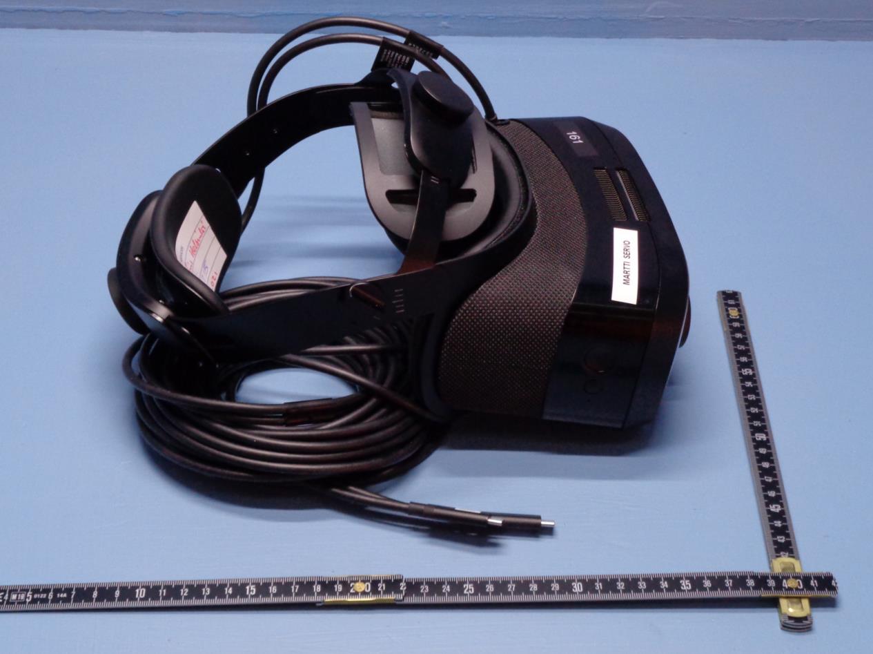
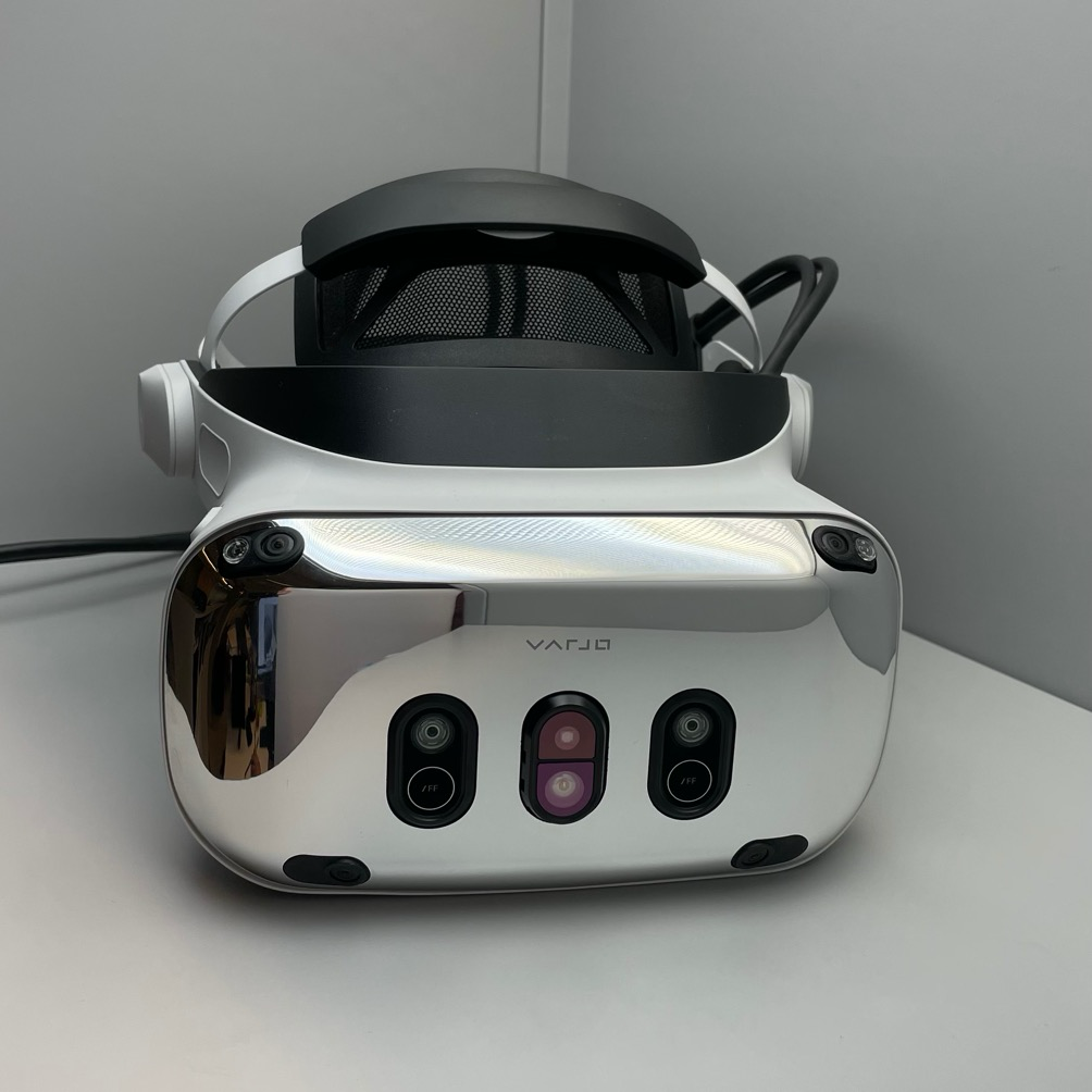
2AROD-004Varjo XR-3

Varjo Technologies Oy
Varjo XR-3 - FCC ID 2AROD-004 - Varjo Technologies Oy
Click to zoom

Application Details

Equipment Class
DTS - Digital Transmission System
Date of Grant
Apr 14, 2021
Application Purpose
Original Equipment
Date of Application
Apr 12, 2021
Equipment Note
Varjo XR-3
Frequency Range
2402.00000000 - 2480.00000000
Company
Varjo Technologies Oy
Country
Finland

Documents & Files

Select a file to view
Users Manual

↗

Cover Letter(s)

↗
↗

External Photos

↗
↗

ID Label/Location Info

↗
↗

Internal Photos

↗

RF Exposure Info

↗

Test Report

↗

Test Setup Photos

↗

Document Text

Text extracted from the exhibit documents filed with the FCC. Open a document above to read the original.

Users Manual

User guide EN DE EN EN EN FR EN ES EN IT EN FI EN SV EN JP EN KO EN HE User guide Benutzerhandbuch Mode d'emploi Guía del usuario Manuale d'uso Käyttöohje Användarguide ユーザーガイド 사용자 설명서 Hebrew 4 ENEN 5 EN EN 2 headset adapters Cleaning cloth 2 power supply units EURO mixed reality headset 6 power plugs, 2 of each In the box VR-3XR-3 UKUSAUSKORCHN Varjo reference marker 2 headset adapters Cleaning cloth 2 power supply units EURO virtual reality headset 6 power plugs, 2 of each UKUSAUSKORCHN 6 ENEN 7 EN EN Connect the headset Varjo headsets are compatible with Windows 10 computers. 1. and : Connect each headset cable to a headset adapter. 2. Headset adapters: Connect each adapter to a DisplayPort port on the graphics card and to a USB-A 3.0 / 3.1 port on the motherboard. For more detailed system requirements, see varjo.com/start/system . Download Varjo Base Varjo Base is the software used to run your headset on a Windows 10 computer. Download Varjo Base to get started. 1. Go to varjo.com/start . 2. Create a Varjo Account. 3. Download and start Varjo Base. 4. Follow the setup instructions. You will need a valid subscription to use your headset. Read more at varjo.com/subscriptions . DisplayPort USB-A 3.0 / 3.1 USB-C USB-C 8 ENEN 9 EN EN Put on the headset To put on the headset, place the front of the headset on your face and pull the headband over the back of your head. You can wear most single-vision eyeglasses while using the headset. Adjust the fit and comfort of the headset when you put it on: : Rotate the back adjustment wheel to tighten the headband. : Rotate the front adjustment wheel to move the headset up or down on your head. Support the headset body with one hand while adjusting. and : Use the side knobs to adjust how the headset fits around your face. The headset is correctly adjusted when it sits comfortably on your head and the image inside the headset is sharp. Using the headset LED patternHeadset status White (blinking)Starting up Green (solid)Working normally Green (pulsing)Idle Green (blinking)Shutting down Orange (solid)Varjo Base not running Action button: interact with your applications Menu button: open the Menu LED status light Headphone connector 10 ENEN 11 EN EN Cleaning the headset Clean the headset regularly, especially when sharing a headset with others. Headset lenses: clean gently with optical lens wipes or a microfiber lens cloth. Headset body, cushions, nose area, and areas surrounding the lenses: clean with non-abrasive antibacterial wipes. You can purchase additional cushions from Varjo Store. Using the Varjo reference marker Use the Varjo reference marker to improve the accuracy of Varjo inside-out tracking. Varjo inside-out tracking is available for the Varjo XR-3 mixed reality headset. For more information, visit varjo.com/start/get-to-know-your-headset . 12 ENEN 13 EN EN Product and safety information Intended use The headset is intended to be used indoors and by adults only. If you do not use the headset as intended, it may cause the headset to malfunction. High-risk use Varjo software and/or products are not designed, engineered, or certified for control of any equipment or system, including aviation, industrial, commercial, military, or medical equipment or systems, in a way where such use or a malfunction of the software or products could with a meaningful probability lead to death or serious bodily injury of any person or animal, or to severe physical or environmental damage (“high-risk use”). VARJO STRONGLY ADVISES AGAINST USING THE SOFTWARE OR PRODUCTS FOR ANY HIGH-RISK USE. If you still decide to use the software and/or products for high-risk use, you do so at your own risk, assume all liability, and agree to take all reasonable precautions to minimize any risk and damage resulting from such high-risk use and/or failure of software and/or products in such high-risk use. Product type label The model name and serial number of the headset are printed on the type label located on the back support of the headband. Health and safety warnings To reduce the risk of personal injury, discomfort, or property damage, please ensure that all users of the headset carefully read the warnings below before using the headset. Before using the headset A comfortable mixed or virtual reality experience requires an unimpaired sense of motion and balance. Do not use the headset if you are sick, tired, sleepy, under the influence of alcohol or drugs, hungover, experiencing digestive problems, under emotional stress or anxiety, suffering from cold, flu, migraines, or headaches, or are not generally feeling well, as it may worsen your condition. Consult a doctor before using the headset if you have any conditions that impair your vision or mobility, are pregnant or elderly, have a heart or other serious medical condition, or suffer from seizures, migraines, or psychiatric conditions. Safe environment Varjo headsets produce an immersive mixed or virtual reality experience that may distract you and make it hard to see your actual surroundings. yRemember that any virtual objects that you see do not exist in the real environment, and their size and location are not real. Do not attempt to sit or stand on virtual objects or use them for support. Be aware of any real-world objects that might be located behind virtual objects. yNever use the headset in situations that require attention, such as while walking, bicycling, or driving. Do not use the headset while in a moving vehicle. yRemember that while you are using the headset, you may be unaware of people entering the area. yBefore using the headset, clear the area of obstacles and hazards, people, furniture, and any other items that may prevent you from moving freely. Also, check that you have enough space above and around you so that you can extend your arms while using the headset. yDo not use the headset near walls, stairs, balconies, windows, open doorways, low ceilings, ceiling fans, light fixtures, breakable items, open f…

Text truncated - open the document above for the full version.

Cover Letter(s)

\I/ TJ trtr AutLoritv to Act as Aeent Date: March29,2021 American Certification Body, Inc. 6731 Whittier Avenue Suite C1 I0 Mclean, VA 22101 To Whom It May Concern: Alex Branton. of Eurofins York. Arabesque House. Monks Cross Drive. YO32 9CW. UK is authorized to act on our behalt. until otherwise notified, for applications to American Certification Body, Inc. (ACB). We certify that we are not subject to denial of federal benefits, that includes FCC benefits, pursuant to Section 5301 of the Anti-Drug Abuse Act of 1988. 21 tJ.S.C. 862. Further, no party, as defined in 47 CFR 1.2002 (b) to the application is subject to denial of federal benefits, that includes FCC benefits. We also declare that the information provided to the FCC is true and correct to the best of our knor.vledge (47 CFR 2.911(d)) and we have been informed of the grantee responsibilities (47 CFR 2.909) with regard to certified equipment. Thank you, Agency A greement Exp iration Date : j!"_gf_Dscgnbq2Q2_1_ %,&-- By (Signaturel) Mauri Ukonmaanaho Head of Manufacturing Operations On behalf of: Vario T Oy (Company Name) Telephone: +358504872467 1 - Must be signed by applicant contact given for applicant on the FCC site, or by the authorized agent if an appropriate authorized agent letter has been provided. Letters should be placed on appropriate letterhead.

Cover Letter(s)

\lr\ fJ El Request for Confidentiali8 Date: March 29,2A21 Subject: Confidantiality Request for: 2ARQD-004 Pursuant to FCC 47 CFR 0.457(d) and 0.459 and IC RSP-100, Section 12.4, the applicant requests that a part of the subject FCC application be held confidential. Type of Confidentiality Requested n Short Term X Permanent tr Short Tenn I Short Tenn tr Permanent *t I ShortTerm X Pennanent n Short Term X Permanent I Short Term f] Permanent [] Short Term X Permanent [] Short Term E Short Temr I Pennanent *3 Exhibit Block Diagrams Extemai Photos Intemal Photos Operation Descriptior/Theory of Operation Parts List & Placement/BOM Tune-Up Procedure Schematics Test Setup Photos User's Manual Vario Technologies Oy has spent substantial effo( in developing this product and it is one of the first of its kind in industry. Having the subject information easily available to "competition" would negate the advantage they have achieved by developing this product. Not protecting the details of the design will result in financial hardship. Permanent Confidentiali§: The applicant requests the exhibits listed above as permanently confidential be permanently withheld from public review due to materials that contain trade secrets and proprietary infbrmation not customarily released to the public. Short-Term Confi dentiality: The applicant requests the exhibits selected above as short term confidential be withheld from public view for a period of 0 days from the date of the Crant of Equiprnent Authorization and prior to marketing. This is to avoid premature release of sensitive infotmation prior to marketing or release of the product to the public. Applicant is also aware that they are responsible to notifo ACB in the event information regarding the product or the product is made available to the public before the requested period has expired. ACB will then release the documents listed above for public disclosure pursuant to FCC Public Notice DA 04-1705. NOTE for lndustry Canada Applications: IC currently only distinguishes Permanent Confidentialify" exhibits as shown above. Short Term confidentiality is not considered applicable to lC applications. Sincerely, By: Mauri Ukonmaanaho (Signature/Title2) (Print name) &tu?{.c#* Vz\ fJ El I - -fhe asterisked items (*) require further information to be provided to ACB before permanent confidentiali§ will be extended to these exhibits. Piease refer to FCC KDB 726920 and the specific Document link for D01 found at: https://apps.fcc.eov/oetcf/kdb/forms/FTSSearchResultPaee.cfrn?switch:P&id:41731 and review section II, 3) regarding specific information that must accompany these requests' 2 - Must be sigrred by applicant contact iirr"t fo. applicant on the FCC site, or by the authorized agent if an appropriate authorized agent letter has been provided. Letters should be placed on appropriate letterhead.

ID Label/Location Info

Item Name Project Name Material Recipe Printing Details Outside Dimension Part W eight (g) Reason for Version Update Sheet Unit A4 Scale Project Number/Year Document Number Customer Item Code Date Customer Version 1 of 1 mm1:1 Hedy Production HMD type label - V0012525 _v1.4 IMDA certification added 06. 04.2021 Label content 1:1 Printed on ribbon: HFY -MRO-RZ1912-002 Background color: Black Text color: Silver Font: Roboto Medium Font size: 5.0 pt DATA MATRIX: -Size: 5.4 x 5.4 mm -18 rows by 18 columns -Cell size: 0.3 mm -Serial number: 18 alphanumeric characters Label assembly To be centered in Ratchet Box Base Assembly tolerance +-0.5mm Hedy Production HMD type label - V0012525 - v1.4 Model: XR-3 (HS-5) S/N: 0000000000000000000 FCC ID: 2AROD-004 IC: 24483-004 Rating: 5V, 2A HVIN: 3006 VST ID: 3106 Made in China Varjo Technologies Oy, Vuorikatu 20, 00100 Helsinki, Finland Complies with IMDA Standards DB106440 Complies with IMDA Standards DB106440 Model: XR-3 (HS-5) S/N:0000000000000000000 FCC ID: 2AROD-004 IC: 24483-004 Rating: 5V, 2A HVIN:3006VST ID3106Made in China Varjo Technologies Oy,Vuorikatu 20,00100 Helsinki, Finland

ID Label/Location Info

8. Label Location  For HMD see HMD type label artwork   For sales box:

Internal Photos

RED ARROWS POINT TO THE ANTENNAS

RF Exposure Info

Project: C5908 Report number: 14095TR3 Customer Details Company name Varjo Technologies Oy Address Vuorikatu 20 00100 Helsinki Finland Contact Martti Timonen Email [email protected] Equipment Under Test: Varjo XR-3 Mixed Reality Headset Operating frequency band: 2400MHz to 24835MHz SAR Exclusion Calculation - FCC The calculation is according to the FCC Knowledge Database (KDB) document KDB 447498 D01 General RF Exposure Guidance V06. Section 4.3.1 General SAR Test Exclusion Bands was applied. Section 4.3.1 a) for 100MHz to 6GHz and test separation distances ≤50mm was specifically applied. According to this section the SAR test exclusion thresholds are determined by the following: Threshold= [ 푃(푚푊) 푑(푚푚) ] . √ 푓(퐺퐻푧) Where P is the maximum measured power of the channel including tune-up tolerance in mW d is the minimum test separation distance in mm f is the RF channel frequency in GHz The minimum test separation distance was considered t be 5mm in consultation with Section 4.2.2 Body-worn accessory exposure conditions. 14095TR3 1 st April 2021 Page 2 of 5 This evaluation of the test exclusion threshold is compared to the threshold limit. a. Limit for 1-g head or body worn devices: threshold limit ≤3 b. Limit for 10-g extremity worn devices: threshold limit ≤7.5 Since the device is head worn the limit “a” applies. 1) Output power measurement results (see test report 14046TR4): Channel (MHz) Antenna port 1 (dBm) Antenna port 2 (dBm) Antenna port 1 (Watts) Antenna port 2 (Watts) Antenna port 1+2 (Watts) 2402 -0.187 -0.252 0.001 0.0009 0.0019 2440 -0.572 -0.705 0.0009 0.0009 0.0018 2480 -1.229 -1.282 0.0008 0.0007 0.0015 2) Rated conducted RF output power and tune-up tolerances: The rated conducted RF output power for transmitter 1 and transmitter 2 with tune-up tolerances are declared as being -0.5 dBm +/- 0.5 dB. The peak antenna gain is 1.1 dBi (1.29 numerical) and thus the maximum EIRP emitted by transmitter 1 as well as transmitter 2 is 1.29 mW. In order to present a worst case approach to RF exposure this EIRP value will be used to determine test exclusion. 3) The calculated threshold for test exclusion was determined while using a distance of 5mm, and the results are tabulated in the table below (stand-alone test exclusion in accordance with KDB publication 447498 D01 General RF Exposure Guidance v06, section 4.3.1 a), for either transmitter 1 or transmitter 2): Channel (MHz) EIRP (mW) Separation distance (mm) Calculated threshold Threshold limit 2402 1.29 5 0.40 3 2440 1.29 5 0.40 3 2480 1.29 5 0.41 3 Conclusion: transmitter 1 and transmitter 2 meet the exemption limit requirements for test exclusion in a stand-alone configuration. 4) Test exclusion based on estimated SAR levels for simultaneous transmissions (KDB publication 447498 D01 General RF Exposure Guidance v06, section 4.3.2 b)): Since the two transmitters can transmit simultaneously the SAR level (1 g, uncontrolled) of each transmitter needs to be estimated and the estimated SAR level of transmitter 1 + estimated SAR 14095TR3 1 st April 2021 Page 3 of 5 level of transmitter 2 must be ≤100% of 1.6 W/kg (see KDB publication 447498 D01 General RF Exposure Guidance v06, section 4.3.2 b)). Estimated SAR level transmitter 1: Channel (MHz) EIRP (mW) Separation distance (mm) Estimated SAR level (W/kg) *) 2402 1.29 ≤5 0.053 2440 1.29 ≤5 0.054 2480 1.29 ≤5 0.054 Estimated SAR level transmitter 2: Channel (MHz) EIRP (mW) Separation distance (mm) Estimated SAR level (W/kg) *) 2402 1.29 ≤5 0.053 2440 1.29 ≤5 0.054 2480 1.29 ≤5 0.054 *) The estimated SAR levels have been calculated using the appropriate equation from KDB publication 447498 D01 General RF Exposure Guidance v06, section 4.3.2 b): [(max. power of channel, including tune-up tolerance, mW) / (min. test separation distance, mm)]·[√f(GHz)/x] W/kg, for test separation distances ≤ 50 mm; where x = 7.5 for 1-g SAR. Estimated SAR level transmitter 1+2: Channel (MHz) Separation distance (mm) Estimated SAR level (W/kg) *) Estimated SAR level as a percentage of 1.6 W/kg (%) 2402 ≤5 0.11 6.7 2440 ≤5 0.11 6.7 2480 ≤5 0.11 6.7 SAR transmitter 1 + SAR transmitter 2 must be ≤100% of 1.6 W/kg Conclusion: the apparatus with transmitter 1 and transmitter 2 transmitting simultaneously meets the exemption limit requirements for test exclusion. 14095TR3 1 st April 2021 Page 4 of 5 SAR Exclusion Calculation - ISED Standard: RSS-102 Radio Frequency (RF) ~Exposure Compliance of Radiocommunication Apparatus (All Frequency Bands), Issue 5 March 2015 incl. Amendment 1of February 2, 2021. Notice 2016-DRS001, July 2020 1) Output power measurement results (see test report 14046TR4): Channel (MHz) Antenna port 1 (dBm) Antenna port 2 (dBm) Antenna port 1 (Watts) Antenna port 2 (Watts) Antenna port 1+2 (Watts) 2402 -0.187 -0.252 0.001 0.0009 0.0019 2440 -0.572 -0.705 0.0009 0.0009 0.0018 2480 -1.229 -1.282 0.0008 0.0007 0.0015 2) Rated conducted RF output power and tune-up tolerances: The rated conducted RF output power for transmitter 1 and transmitter 2 with tune-up tolerances are declared as being -0.5 dBm +/- 0.5 dB. The peak antenna gain is 1.1 dBi (1.29 numerical) and thus the maximum EIRP emitted by transmitter 1 as well as transmitter 2 is 1.29 mW. In order to present a worst case approach to RF exposure this EIRP value will be used to determine test exclusion. 3) Test exclusion was determined while using a distance of ≤5mm and the results are tabulated in the table below (stand-alone test exclusion in accordance with RSS-102, section 2.5.1, for either transmitter 1 or transmitter 2): Channel (MHz) EIRP (mW) Separation distance (mm) Exemption limit (mW) *) 2402 1.29 ≤5 4.26 2440 1.29 ≤5 4.05 2480 1.29 ≤5 3.94 Conclusion: transmitter 1 and transmitter 2 meet the exemption limit requirements for test exclusion in a stand-alone configuration *) Exemption limit in mW for 2402 MHz, 2440 MHz and 2480 MHz has been calculated using linear interpolation based on 1900 – 2450 MHz (7 mW – 4 mW) and 2450 – 3500 …

Text truncated - open the document above for the full version.

Test Report

Test Report for the FCC and ISED Testing of a Varjo XR-3 Headset for Varjo Technologies Oy Test Report number 14046TR5 Project number C5908 Author: ................ ...................................................................................... M Render BSc(Hons), PhD, MIET Senior Engineer Checked: ..................................... . ............................................................. J Beevers MPhys(Hons), PhD Test Engineer Approved: ................................................................................................. Mr C W Greenfield, BEng (Hons) Issue Description Issue by Date 5 Copy 1 Copy 2 PDF X CG 13 th April 2021 This report shall not be reproduced, except in full without the prior written approval of Eurofins York The results contained in this report are only applicable to the apparatus tested. Commercial in Confidence Report Number: 14046TR5 Date: 13 th April 2021 Page 2 of 74 FCC Report Template Issue 5 CONTENTS Test Report Change History .................................................................................................................. 4 Section 1 Test Location ................................................................................................................. 5 1.1 UKAS Accreditation ................................................................................................................... 5 Section 2 Customer Information ................................................................................................... 6 Section 3 Equipment Details ......................................................................................................... 7 3.1 Equipment Under Test (EUT) ..................................................................................................... 7 3.2 EUT Photographs ...................................................................................................................... 9 3.3 Configuration of EUT.................................................................................................................. 9 3.4 EUT Monitoring/Auxiliary Equipment .......................................................................................... 9 3.5 Monitoring Software ................................................................................................................... 9 Section 4 Test Specifications ...................................................................................................... 10 4.1 Knowledge Database References ............................................................................................ 12 4.1.1 Radiated Emissions (30MHz to 1000MHz).......................................................................... 12 4.1.2 Radiated Emissions (1GHz to 40GHz) ................................................................................ 12 4.2 Compliance Statement ............................................................................................................. 12 Section 5 Spurious Emission Results – Radiated and Conducted ............................................ 13 5.1 Test Specification..................................................................................................................... 13 5.2 Procedure and Test Software Version ...................................................................................... 13 5.3 Radiated Emissions (30MHz to 1GHz) ..................................................................................... 14 5.3.1 Limits at 3m ....................................................................................................................... 14 5.3.2 Emissions measurements .................................................................................................. 14 5.3.3 Date of Test ....................................................................................................................... 14 5.3.4 Test Area ........................................................................................................................... 14 5.3.5 Tested by ........................................................................................................................... 14 5.3.6 Test Setup ......................................................................................................................... 15 5.3.7 Electric field emissions, 30MHz to 1GHz ............................................................................ 16 5.3.8 Example field strength calculation ...................................................................................... 19 5.3.9 Sample Data ...................................................................................................................... 19 5.4 Radiated Emissions (1GHz to 18GHz) ..................................................................................... 20 5.4.1 Limits ................................................................................................................................. 20 5.4.2 Receiver Settings ............................................................................................................... 20 5.4.3 Emissions measurements .................................................................................................. 20 5.4.4 Date of Test ....................................................................................................................... 20 5.4.5 Test Area ........................................................................................................................... 20 5.4.6 Tested by ........................................................................................................................... 20 5.4.7 Test Setup ......................................................................................................................... 21 5.4.8 Exploratory Radiated Emission Maximization...................................................................... 22 5.4.9 El…

Text truncated - open the document above for the full version.

Test Setup Photos

Project: C5908 Radiated electric field emissions 30MHz to 1GHz Radiated emissions 1-18GHz – radiated spurious for restricted bands and band edge measurements Radiated emissions manual investigation 18-26GHz AC mains conducted emissions AC mains conducted emissions AC mains conducted emissions AC mains conducted emissions

Contact Information

Applicant

Martti Timonen(Director, Device Hardware)
[email protected]+358405948628Fax: +358405948628

Technical Contact

Varjo Technologies OyAri Pitkanen
[email protected]

Vuorikatu 20 · Helsinki · Finland

Non-Technical Contact

Varjo Technologies OyMauri Ukonmaanaho
[email protected]011358504872467

Test Firm

Eurofins York LtdNick Wainwright
[email protected]44 330 430 3456

Technical Specifications

#Rule PartsFrequency RangePower Output
215C2.40 GHz - 2.48 GHz1.00 mW
Confidentiality
Long Term
Grant Notes
Power output is conducted. The antenna(s) used for this transmitter must not be co-located or operating in conjunction with any other antenna or transmitter.

Other Applications from Varjo Technologies Oy

Virtual reality headset - FCC ID 2AROD-005 - Varjo Technologies Oy
2AROD-005

Virtual reality headset

Nov 28, 2023

Equipment Class

DTS - Digital Transmission System